

Page 1

Installation Guide
Isilon
NL400
Install a new node
120-0095-01
REV J
May, 2016
l
About this guide.........................................................................................................2
l
Drive types.................................................................................................................2
l
Confirm SSD compatibility......................................................................................... 2
l
Unpack and verify components.................................................................................. 2
l
Install the node in a rack............................................................................................3
l
Install the drives in the node......................................................................................6
l
Install the front panel.................................................................................................9
l
Back panel...............................................................................................................10
l
Connect the internal cluster network........................................................................ 10
l
Connect the external client network......................................................................... 11
l
Connect the power supply........................................................................................12
l
Configure the node.................................................................................................. 13
l
Front panel LCD menu.............................................................................................. 16
l
Update the install database..................................................................................... 18
l
Where to go for support............................................................................................18
Page 2

About this guide
This guide describes how to install a new EMC Isilon node.
You can follow the procedure in this guide to:
l
Install several nodes to create a new cluster.
l
Add a new node to an existing cluster.
The installation procedure is the same whether you are creating a new cluster or adding a
node to an existing cluster. When you reach the step where you configure the node, you
will select whether you are creating a new cluster or adding a node to an existing cluster.
Note
If you are installing multiple nodes, repeat this procedure for each node. Power up each
node individually before installing the next node.
Drive types
This procedure applies to nodes that contain any of the following drive types: selfencrypting drives (SEDs), hard disk drives (HDDs), and solid state drives (SSDs).
If you are performing this procedure with a node containing SSDs, follow the additional
steps provided in this document to ensure compatibility with the cluster.
If you are performing this procedure with a node containing SEDs, the node might take up
to two hours longer to join the cluster than a node with standard drives. Do not power
down the node during the join process.
Confirm SSD compatibility
If you are installing a new solid state drive (SSD) into a cluster, you must confirm that the
drive you have onsite is compatible with the cluster.
See the Isilon Supportability and Compatibility Guide to determine whether the drive you
have is compatible with the cluster.
Unpack and verify components
Before you install any equipment, inspect it to make sure that no damage occurred during
transit.
Procedure
1. Remove the node components from the shipping package and inspect the
components for any sign of damage. If the components appear damaged in any way,
notify Isilon Technical Support. Do not use a damaged component.
Note
To avoid personal injury or damage to the hardware, always use two people to lift and
move nodes.
Installation Guide
2 NL400 Installation Guide
Page 3
Install the node in a rack
Isilon nodes mount in standard ANSI/EIA RS310D 19-inch rack systems and use a sliding
rail system to provide easy access to the node.
The sliding rail kit is compatible with rack cabinets with the following hole types:
l
3/8 inch square holes
l
9/32 inch round holes
l
10-32, 12-24, M5X.8, or M6X1 pre-threaded holes
Rail kit mounting brackets adjust in length from 24 inches to 36 inches to accommodate
a variety of cabinet depths. The slide rails are not left-specific or right-specific and can be
installed on either side of the rack.
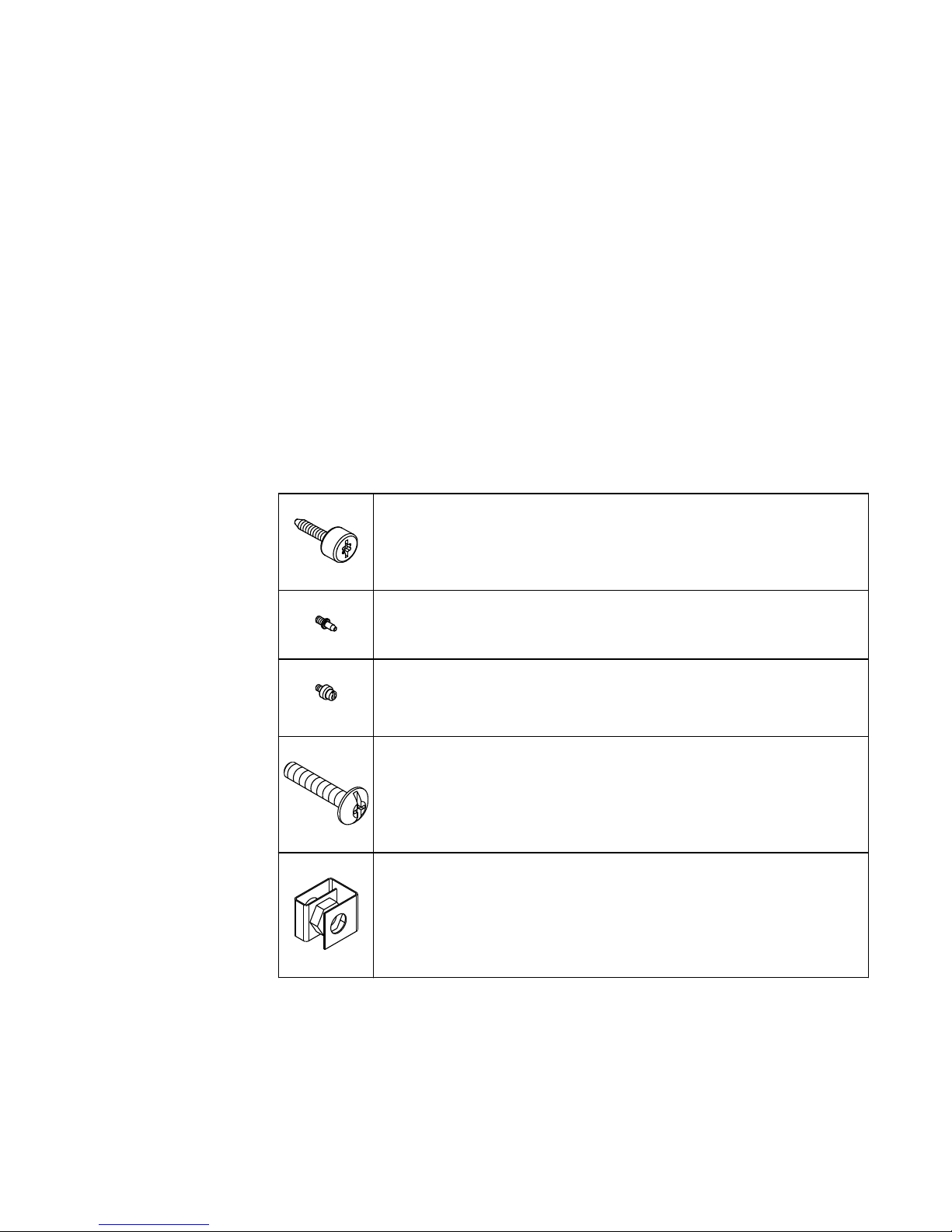
Verify rail kit contents
Remove the rail hardware kit from the shipping container and verify that you have all of
the required components.
Four 8-32 × 0.75 inch knurled slide rail mounting screws.
Secures the slide rails to the rack cabinet.
Eight 8-32 × 0.25 inch shoulder alignment pins.
Use only for a pre-threaded rack cabinet.
Eight 8-32 × 0.25 inch step alignment pins.
Used only for square-hole or round-hole rack cabinet. These pins are preassembled on the rails.
Two 10-32 × 1 inch truss head chassis retaining screws.
Secures the node in the rack cabinet.
Two 10-32 g-style clip-on nut retainers.
Secures the node in the rack cabinet. Used only for square-hole or roundhole rack cabinets.
Determine correct alignment pins
Determine the type of alignment pins you need for your rack cabinet.
The rails are preconfigured for rack cabinets that have 3/8 inch square-holes or 9/32 inch
round-holes, but the rails can be modified to accommodate racks with pre-threaded
holes.
Install a new node
Install the node in a rack 3
Page 4
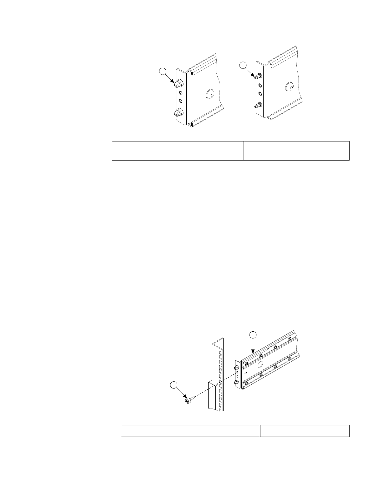
1
2
1. Step Alignment Pin for Round-Hole or Square-
Hole Racks
2. Shoulder Alignment Pin for PreThreaded Racks
Procedure
1. Confirm the type of rack you are installing the rails in and replace the alignment pins if
necessary.
l
If you are installing the rails in a rack with 3/8 inch square-holes or 9/32 inch
round-holes, you do not need to adjust the alignment pins.
2. If you are installing the rails in a rack with pre-threaded holes, replace the preassembled step alignment pins in the ends of the outer rails with the proper shoulder
alignment pins.
Mount the outer rails
Mount the outer rails in the rack cabinet.
Procedure
1. Adjust the outer rail rear slide brackets to fit the depth of the cabinet, ensuring that
the alignment pins protrude through the rack mounting rails.
2. Insert an 8-32 knurled thumb screw through each rail, and then tighten the screws to
secure the outer rails to the rack mounting rails.
1
2
1
1. Slide rail mounting screw
2. Outer slide rail
3. Attach a clip-on nut retainer to the third hole above the slide rail on each side of the
rack.
Installation Guide
4 NL400 Installation Guide
Page 5
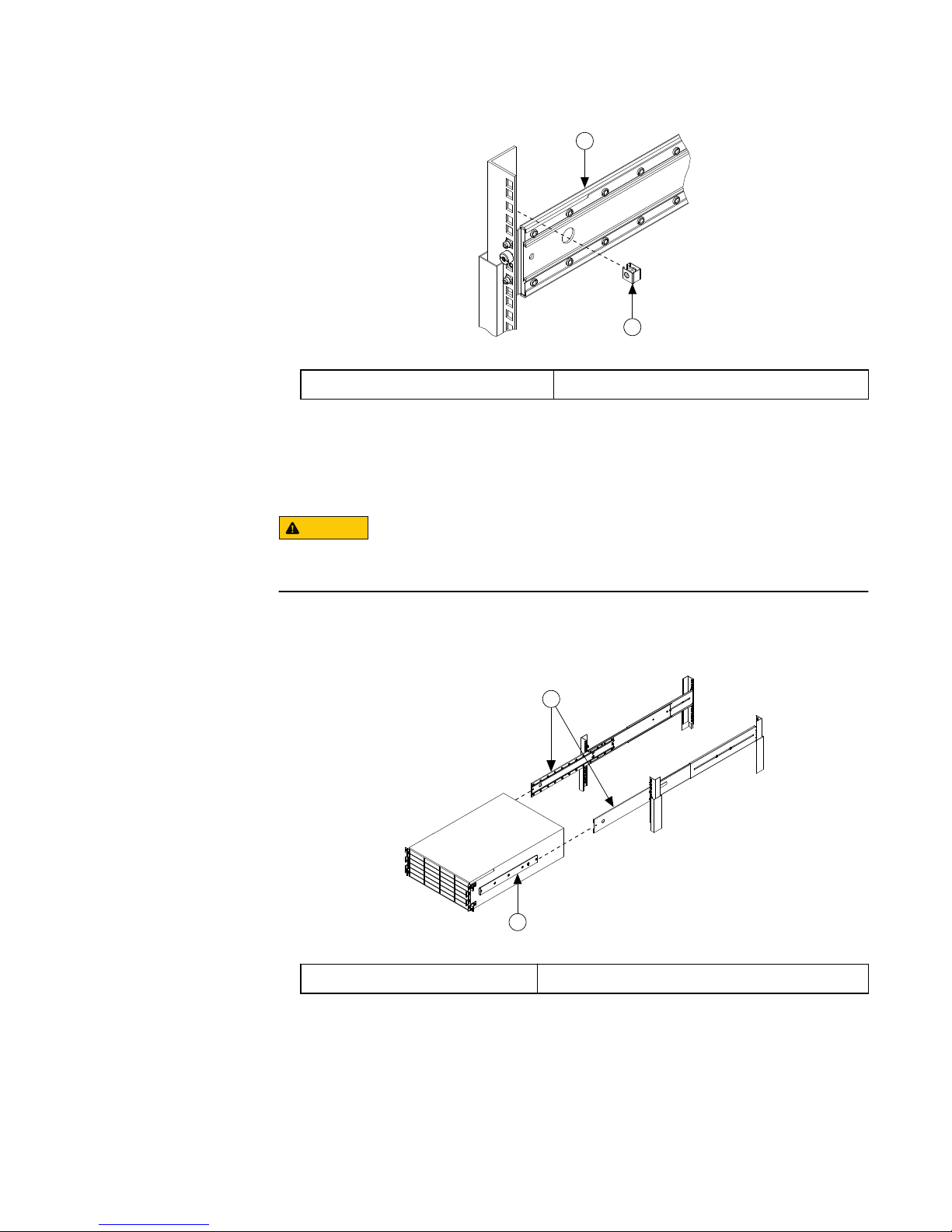
1
2
1. Outer slide rail 2. Clip-on nut retainer
Install the node in the rack
Secure the node to the storage rack.
CAUTION
To minimize the chance of personal injury or equipment damage, and to ensure proper
slide rail installation, it is recommended that two people lift and move the node.
Procedure
1. Fully extend each intermediate rail until the rail locks into place.
1
2
1. Inner Slide Rail
2. Intermediate Slide Rail
2. Keep the node level with the rails and align the ends of the inner rails with the ends of
the intermediate rails.
3. Insert the inner slide rails into the intermediate slide rails, then retract the slide rails
until the node is completely inserted in the rack cabinet.
4. Tighten the chassis retaining screws to secure the node in the rack.
Install a new node
Install the node in the rack 5
Page 6
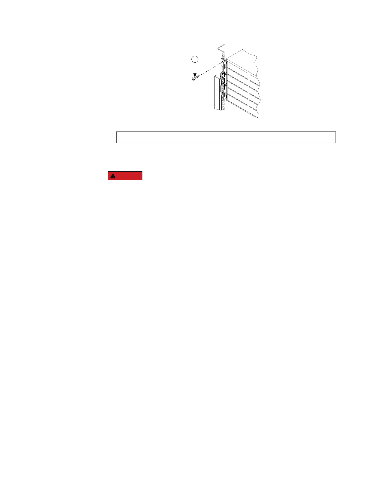
1
1. Chassis Retaining Screw
Results
DANGER
Do not continue with this procedure until you have confirmed the following:
1. Both rails are secured to the rack and all mounting screws are in place and
tightened.
2. The inner slide rails attached to the node are inserted correctly, and firmly secured,
in the intermediate slide rails that are attached to the rack.
If you fail to attach the node to the rails correctly it can lead to severe injury when the
node is pulled for future maintenance.
Install the drives in the node
After the node is secured in the rack, install the drives in the node.
There are 36 drive bays that you must fill with drives: twenty-four in the front of the node,
and twelve in the back of the node.
Procedure
1. With the locking handle on the drive open, insert a drive into an empty drive bay by
sliding the drive along the bay rails until it stops.
Do not force the drive into the drive bay. Forcing the drive into the drive bay could
damage both the drive and the drive bay.
Installation Guide
6 NL400 Installation Guide
Page 7

1
2
1. Locking handle 2. Drive bay
2. Hold the drive in place and gently push the drive locking handle down against the end
of the drive to secure the drive in the drive bay.
3. Repeat the previous steps until the front bays of the node are full.
Note
Drives that are not fully seated will not be recognized when the node starts, and a red
light will appear below the drive. To avoid this error, run your finger across all the
installed drives to ensure that they are seated evenly.
4. On the back panel of the node, remove the rear EMI shield.
There are two vertical handles on either end of the shield. To remove the shield, press
the handles toward the center of the shield while pulling away from the node.
Install a new node
Install the drives in the node 7
Page 8

1
1. Rear EMI shield
5. Insert and lock drives into the back bays until they are full.
1
2
3
1. Rear EMI shield 2. Locking handle 3. Drive bay
6. Replace the rear EMI shield.
Installation Guide
8 NL400 Installation Guide
Page 9

Install the front panel
The front panel covers the drives and provides a keypad and LCD, which displays status
information. You can use the keypad and LCD to perform basic configuration tasks.
Procedure
1. Install the front panel assembly by aligning the front panel with the front of the node
and then pressing the front panel onto the node.
1
1. Front panel
Install a new node
Install the front panel 9
Page 10

Back panel
The back panel provides connections for power, network access, and serial
communication, as well as access to the backup batteries and power supplies.
3
21
5
6
8
9
10
4
7
1. Power supplies 6. Serial port
2. Batteries 7. VGA port
3. Power switch 8. 1 GigE external network ports
4. PS/2 ports 9. 1 GigE or 10 GigE external network ports
5. USB ports 10. InfiniBand internal network ports
CAUTION
Only trained EMC Isilon personnel should connect to the node with the PS/2, USB or VGA
ports. For direct access to the node, connect to the serial port.
LEDs
Do not rely on LEDs to determine the health of a node or node component. If any
hardware component is in an error state, identify and troubleshoot the error through
OneFS events and alerts. The behavior of the lights can change after a firmware update
and might not accurately reflect the health of a node.
Connect the internal cluster network
The InfiniBand cable connects the node to the cluster's internal network so the node can
communicate with the other nodes in the cluster.
Procedure
1. With an InfiniBand cable, connect the int-a port to the network switch for the Internal
A network.
Installation Guide
10 NL400 Installation Guide
Page 11

2. If the network topology supports a second internal network, connect the int-b port to a
separate network switch for the int-b network.
1 2
1. int-a port 2. int-b port
Connect the external client network
The ethernet cable connects the node to the cluster's external network so the node can
communicate with external clients.
Complete the following steps to connect the node with the switch for the external
network.
Procedure
1. With an ethernet cable, connect the ext-1 port on the node to the switch for the
external network.
For additional 1 Gb connections, use the ext-2 port.
CAUTION
You must connect the 1 Gb ext-1 port to the external network, even if you were
planning on only connecting the 10Gb ports. If you do not connect the 1 Gb ext-1
port, and if the node cannot authenticate to your Active Directory (AD) server, it is
possible that the node will not join the cluster and that you will experience additional
downtime.
2. If your node is equipped with 10Gb ports, connect the 10gige-1 port on the node to
the switch for the external network.
For additional connections, use the 10gige-2 port.
Install a new node
Connect the external client network 11
Page 12

3
4
1
2
1. ext-1 port 3. ext-3 or 10gige-1 port
2. ext-2 port 4. ext-4 or 10gige-2 port
Connect the power supply
Each node contains redundant power supplies to ensure that the node remains powered
in case a power supply fails.
Procedure
1. Connect the power supply cables to the power connectors on the back panel of the
node.
2. Connect each power supply cable to a separate power source.
A green LED labeled AC will turn on when AC power is present.
Note
Both power supplies must be connected. Operating a node using only one power
supply for an extended period will shorten the life of the power supply. If the
installation site has a limited number of power outlets, contact Isilon Technical
Support for additional information before using a Y-cable to power both supplies from
a single power source.
CAUTION
If this node loses power, the NVRAM battery will sustain the cluster journal on the
NVRAM card for five days. If you do not restore power to the node after five days, it is
possible that you will lose data.
Installation Guide
12 NL400 Installation Guide
Page 13

Configure the node
Before using the node, you must either create a new cluster or add the node to an
existing cluster.
SmartLock compliance mode
You can configure nodes to operate in SmartLock compliance mode. You should only
choose to run your cluster in SmartLock compliance mode if your data environment must
comply with SEC rule 17-a4(f).
Compliance mode controls how SmartLock directories function and limits access to the
cluster in alignment with SEC rule 17-a4(f).
A valid SmartLock license is required to configure a node in compliance mode.
CAUTION
Once you select to run a node in SmartLock compliance mode, you cannot leave
compliance mode without reformatting the node.
SmartLock compliance mode is incompatible with Isilon for vCenter, VMware vSphere
API for Storage Awareness (VASA), and the VMware vSphere API for Array Integration
(VAAI) NAS Plug-In for Isilon.
Connect to the node using a serial cable
You can use a null modem serial cable to provide a direct connection to a node.
Before you begin
If no serial ports are available, you can use a USB-to-serial converter.
Procedure
1. Connect a null modem serial cable to the serial port of a computer, such as a laptop.
2. Connect the other end of the serial cable to the serial port on the back panel of the
node.
3. Start a serial communication utility such as Minicom (UNIX) or PuTTY (Windows).
4. Configure the connection utility to use the following port settings:
Setting
Value
Transfer rate 115,200 bps
Data bits 8
Parity None
Stop bits 1
Flow control
(RTS/CTS)
Hardware
5. Open a connection to the node.
Install a new node
Configure the node 13
Page 14

Run the configuration wizard
The Isilon configuration wizard starts automatically when a new node is powered on. The
wizard provides step-by-step guidance for configuring a new cluster or adding a new
node to an existing cluster.
The following procedure assumes that there is an open serial connection to a new node.
Note
You can type back at most prompts to return to the previous step in the wizard.
Procedure
1. Depending on whether you are creating a new cluster, joining a node to an existing
cluster, or preparing a node to run in SmartLock compliance mode, choose one of the
following options:
l
To create a new cluster, type 1.
l
To join the node to an existing cluster, type 2.
l
To exit the wizard and configure the node manually, type 3.
l
To restart the node in SmartLock compliance mode, type 4.
CAUTION
If you choose to restart the node in SmartLock compliance mode, the node
restarts and returns to this step. Selection 4 changes to enable you to disable
SmartLock compliance mode. This is the last opportunity to back out of
compliance mode without reformatting the node.
2. Follow the prompts to configure the node.
For new clusters, the following table lists the information necessary to configure the
cluster. To make sure the installation process is not interrupted, we recommend that
you collect this information prior to installation.
Setting
Description
SmartLock compliance license A valid SmartLock license. For clusters in compliance
mode only.
Root password The password for the root user. Clusters in compliance
mode do not allow a root user and request a compliance
administrator (compadmin) password in place of a root
user.
Admin password The password for the administrator user.
Support IQ
l
Company name
l
Contact name
l
Contact phone number
l
Contact email
SupportIQ enables Isilon Technical Support to remotely
monitor a cluster, run scripts, and download information
to assist in troubleshooting cluster issues.
Cluster name The name used to identify the cluster.
Character encoding The character encoding for the cluster.
Installation Guide
14 NL400 Installation Guide
Page 15

Setting Description
The default character encoding is UTF-8.
int-a network settings
l
Netmask
l
IP range
The network settings used by the int-a network. The int-a
network is used for communication between nodes.
The int-a network must be configured with IPv4.
The int-a network must be on a separate subnet from an
int-b/failover network.
int-b / failover network settings
l
Netmask
l
IP range
l
Failover IP range
The network settings used by the optional int-b/failover
network. The int-b network is used for communication
between nodes and provides redundancy with the int-a
network.
The int-b network must be configured with IPv4.
The int-a and int-b networks must be on separate
subnets.
The failover IP range is a virtual IP range that is resolved
to either one of the active ports during failover.
ext-1 network settings
l
Netmask
l
MTU
l
IP range
The network settings used by the ext-1 network. The
ext-1 network is used by clients to access the cluster.
The default ext-1 network can be configured with IPv4 or
IPv6 addresses.
You can configure the external network with IPv6
addresses by entering an integer less than 128 for the
netmask value. The standard external netmask value for
IPv6 addresses is 64.
If you enter a netmask value with dot-decimal notation,
you must use IPv4 addresses for your IP range.
Default gateway The IP address of the optional gateway server through
which the cluster communicates with clients outside the
subnet. Enter an IPv4 or IPv6 address, depending on
how you configured the ext-1 network settings.
SmartConnect settings
l
SmartConnect zone name
l
SmartConnect service IP
SmartConnect balances client connections across nodes
in a cluster.
For information about configuring SmartConnect, see the
OneFS Administration Guide
.
DNS settings
l
DNS servers
l
DNS search domains
The DNS settings for the cluster.
Enter a comma-separated list to specify multiple DNS
servers or search domains. Enter IPv4 or IPv6 addresses,
depending on how you configured the ext-1 network
settings.
Date and time settings
l
Time zone
l
Day and time
The day and time settings for the cluster.
Cluster join mode The method that the cluster uses to add new nodes.
Choose one of the following options:
Install a new node
Run the configuration wizard 15
Page 16

Setting Description
Manual join
Enables either a configured node in the existing
cluster, or a new node, to issue a request to join
the cluster.
Secure join
A configured node in the existing cluster must
invite a new unconfigured node to join the cluster.
Note
If you are installing a node that contains SEDs (self-encrypting drives), the node will
format the drives at this time. The formatting process might take up to two hours to
complete.
Front panel LCD menu
You can perform certain actions and check a node's status from the LCD menu on the
front panel of the node.
LCD Interface
The LCD interface is located on the node front panel. The interface consists of the LCD
screen, a square button for making selections, and four arrow buttons for navigating
menus.
The LCD screen will be dark until you activate it. To activate the LCD screen and view the
menu, press the square selection button.
You can press the right arrow button to move to the next level of a menu.
Attach menu
The Attach menu contains the following sub-menu:
Drive
Adds a drive to the node. After you select this command, you can select the drive bay
that contains the drive you would like to add.
Status menu
The Status menu contains the following sub-menus:
Alerts
Displays the number of critical, warning, and informational alerts that are active on
the cluster.
Cluster
The Cluster menu contains the following sub-menus:
Details
Displays the cluster name, the version of OneFS installed on the cluster, the
health status of the cluster, and the number of nodes in the cluster.
Capacity
Displays the total capacity of the cluster and the percentage of used and
available space on the cluster.
Installation Guide
16 NL400 Installation Guide
Page 17

Throughput
Displays throughput numbers for the cluster as <in> | <out> | <total>.
Node
The Node menu contains the following sub-menus:
Details
Displays the node ID, the node serial number, the health status of the node,
and the node uptime as <days>, <hours>:<minutes>:<seconds>
Capacity
Displays the total capacity of the node and the percentage of used and
available space on the node.
Network
Displays the IP and MAC addresses for the node.
Throughput
Displays throughput numbers for the node as <in> | <out> | <total>.
Disk/CPU
Displays the current access status of the node, either Read-Write or Read-Only.
Also displays the current CPU throttling status, either Unthrottled or Throttled.
Drives
Displays the status of each drive bay in the node.
You can browse through all the drives in the node with the right and left navigation
buttons.
You can view the drives in other nodes in the cluster with the up and down
navigation buttons. The node you are viewing will display above the drive grid as
Drives on node:<node number>.
Hardware
Displays the current hardware status of the node as <cluster name>-<node
number>:<status>.
Also displays the Statistics menu.
Statistics
Displays a list of hardware components. Select one of the hardware
components to view statistics related to that component.
Update menu
The Update menu allows you to update OneFS on the node. Press the selection button to
confirm that you would like to update the node. You can press the left navigation button
to back out of this menu without updating.
Service menu
The Service menu contains the following sub-menus:
Throttle
Displays the percentage at which the CPU is currently running.
Press the selection button to throttle the CPU speed.
Install a new node
Front panel LCD menu 17
Page 18

Unthrottle
Displays the percentage at which the CPU is currently running.
Press the selection button to set CPU speed to 100%.
Read-Only
Press the selection button to set node access to read-only.
Read-Write
Press the selection button to set node access to read-write.
UnitLED On
Press the selection button to turn on the unit LED.
UnitLED Off
Press the selection button to turn off the unit LED.
Shutdown menu
The Shutdown menu allows you to shut down or reboot the node. This menu also allows
you to shut down or reboot the entire cluster. Press the up or down navigation button to
cycle through the four shut down and reboot options, or to cancel out of the menu.
Press the selection button to confirm the command. You can press the left navigation
button to back out of this menu without shutting down or rebooting.
Update the install database
After all work is complete, update the install database.
Procedure
1. Browse to the EMC Product Registration and Install base Maintenance service portal,
at: http://emc.force.com/createPSCcase.
2. Select the Product Registration and Install Base Maintenance
option.
3. To open the form, select the IB Status Change option.
4. Complete the form with the applicable information.
5. To submit the form, click Submit.
Where to go for support
Contact EMC Isilon Technical Support for any questions about EMC Isilon products.
Online Support
Live Chat
Create a Service Request
Telephone
Support
United States: 1-800-SVC-4EMC (800-782-4362)
Canada: 800-543-4782
Worldwide: +1-508-497-7901
For local phone numbers for a specific country, see EMC Customer
Support Centers.
Installation Guide
18 NL400 Installation Guide
Page 19

Help with Online
Support
For questions specific to EMC Online Support registration or access,
email support@emc.com.
Isilon Info Hubs For the list of Isilon info hubs, see the Isilon Info Hubs page on the
EMC Isilon Community Network. Isilon info hubs organize Isilon
documentation, videos, blogs, and user-contributed content into
topic areas, making it easy to find content about subjects that
interest you.
Support for IsilonSD Edge
If you are running a free version of IsilonSD Edge, community support is available through
the EMC Isilon Community Network. However, if you have purchased one or more licenses
of IsilonSD Edge, you can contact EMC Isilon Technical Support for assistance, provided
you have a valid support contract for the product.
Install a new node
Where to go for support 19
Page 20

Copyright © 2016 EMC Corporation. All rights reserved. Published in the USA.
Published May, 2016
EMC believes the information in this publication is accurate as of its publication date. The information is subject to change without
notice.
The information in this publication is provided as is. EMC Corporation makes no representations or warranties of any kind with
respect to the information in this publication, and specifically disclaims implied warranties of merchantability or fitness for a
particular purpose. Use, copying, and distribution of any EMC software described in this publication requires an applicable software
license.
EMC², EMC, and the EMC logo are registered trademarks or trademarks of EMC Corporation in the United States and other countries.
All other trademarks used herein are the property of their respective owners.
For the most up-to-date regulatory document for your product line, go to EMC Online Support (https://support.emc.com).
Installation Guide
20 NL400 Installation Guide
 Loading...