

Page 1

HAMILTON-T1
EMC Declarations
2020-09-04
627049/01
Page 2
EMC declarations IEC 60601-1-2:2007, 3rd edition
EMC declarations IEC 60601-1-2:2007, 3rd edition
HAMILTON-T1 EMC Declarations
This guide provides information about
EMC declarations. It is designed for use
together with your ventilator Operator’s
The HAMILTON-T1 ventilator is intended
for use in the electromagnetic environment specified in Tables 1, 2, and 3. The
HAMILTON-T1 ventilator user should
ensure that it is used in such an environ-
ment.
Manual, and refers to information provided there.
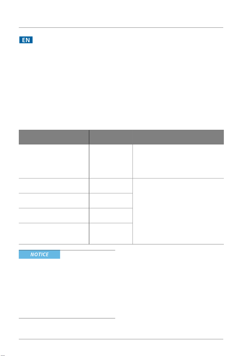
Table 1 Guidance and manufacturer's declaration – electromagnetic emissions
(IEC 60601-1-2)
Emissions test Compliance Electromagnetic environment guid-
ance
RF emissions
CISPR 11
RF emissions
CISPR 11, conducted
RF emissions
CISPR 11, radiated
Harmonic emissions
IEC 61000-3-2
Voltage fluctuations/flicker
emissions
IEC 61000-3-3
Group 1 The HAMILTON-T1 ventilator uses
RF energy only for its internal function.
Therefore, its RF emissions are very low
and are not likely to cause any interference in nearby electronic equipment.
Class B The HAMILTON-T1 ventilator is suitable
for use in all establishments other than
Class B
Class A
Complies
domestic and those directly connected
to the public low-voltage power supply
network that supplies buildings for
domestic purposes.
• UT is the AC mains voltage prior to
application of the test level.
• At 80 MHz and 800 MHz, the higher
frequency range applies.
• These guidelines may not apply in all
situations. Electromagnetic propagation
is affected by absorption and reflection
from structures, objects, and people.
2 English | 627049/01
Page 3

Table 2 Guidance and manufacturer's declaration – electromagnetic immunity
(IEC 60601-1-2)
Immunity test IEC 60601 test
level
Electrostatic
discharge (ESD)
±6 kV contact
±8 kV air
IEC 61000-4-2
Electrical fast transient/burst
IEC 61000-4-4
±2 kV for power
supply lines
±1 kV for input/
output lines
Surge
IEC 61000-4-5
±1 kV line(s) to
line(s)
±2 kV line(s) to
earth
Voltage dips, short
interruptions, and
voltage variations on
power supply input
lines
IEC 61000-4-11
Power frequency
< 5% U
dip in U
0.5 cycle
40% U
in U
70% U
in
<5% U
in U
3 A/m 30 A/m The power frequency magnetic
1
(>95%
T
) for
T
(60% dip
T
) for 5 cycles
T
(30% dip
T
U
) for 25 cycles
T
(>95% dip
T
) for 5 s
T
(50/60 Hz) magnetic field
IEC 61000-4-8
Compliance level Electromagnetic
environment guidance
±8 kV contact
±15 kV air
Floors should be wood, concrete, or ceramic tile. If floors
are covered with synthetic
material, the relative humidity
should be at least 5%.
±2 kV for power
supply lines
±1 kV for input/
Mains power quality should be
that of a typical commercial or
hospital environment.
output lines
±1 kV line(s) to
line(s)
±2 kV (line(s) to
Mains power quality should be
that of a typical commercial or
hospital environment.
earth
<5% U
in U
) for 0.5 cycle
T
40% U
in U
) for 5 cycles
T
70% U
in U
) for 25 cycles
T
<5% U
) for 5 s
in U
T
(>95% dip
T
(60% dip
T
(30% dip
T
(>95% dip
T
Mains power quality should be
that of a typical commercial or
hospital environment.
If the user of the HAMILTONT1 ventilator requires continued operation during power
mains interruptions, it is recommended that the HAMILTON-T1 ventilator be powered
from an uninterruptible power
supply or battery.
field should be at levels characteristic of a typical location in
a typical commercial or hospital environment.
Hamilton Medical | HAMILTON-T1 EMC Declarations 3
Page 4
EMC declarations IEC 60601-1-2:2007, 3rd edition
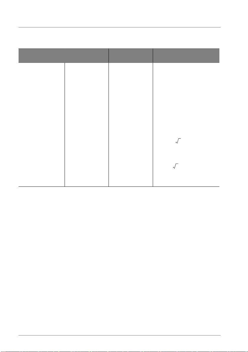
d 0.35 P=
d 1.2 P=
Table 2 Guidance and manufacturer's declaration – electromagnetic immunity
(IEC 60601-1-2)
(cont.)
Immunity test IEC 60601 test
level
Conducted RF
IEC 61000-4-6
3 Vrms
150 kHz to 80 MHz
outside ISM bands
10 Vrms
150 kHz to 80 MHz
in ISM bands
5
Compliance level Electromagnetic
environment guidance
Portable and mobile RF communications equipment should
be used no closer to any part
of the HAMILTON-T1 ventilator, including cables, than the
recommended separation distance calculated from the
equation applicable to the frequency of the transmitter.
Recommended separation distance:
10 Vrms
2
10 Vrms
4 English | 627049/01
Page 5
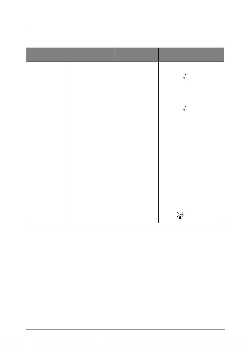
Table 2 Guidance and manufacturer's declaration – electromagnetic immunity
d 0.40 P=
d 0.77 P=
(IEC 60601-1-2)
(cont.)
Immunity test IEC 60601 test
level
Radiated RF
IEC 61000-4-3
10 V/m
80 MHz to 2.5 GHz
Compliance level Electromagnetic
environment guidance
30 V/m
80 MHz to 800 MHz
80 MHz to 2.5 GHz
800 MHz to 2.5 GHz
where
P is the maximum out-
put power rating of the transmitter in watts (W) according
to the transmitter manufacturer and d is the recommended separation distance in
meters (m).
3
Field strengths from fixed RF
transmitters, as determined by
an electromagnetic site
4
survey
, should be less than
the compliance level in each
frequency range
ence may occur in the vicinity
of equipment marked with the
symbol
5
. Interfer-
1. UT is the AC mains voltage prior to application for the test level.
2. The ISM (industrial, scientific and medical) bands between 150 kHz and 80 MHz are 6.765 MHz to 6.795 MHz; 13.553
MHz to 13.567 MHz; 26.957 MHz to 27.283 MHz; and 40.66 MHz to 40.70 MHz.
3. The compliance levels in the ISM frequency bands between 150 kHz and 80 MHz and in the frequency range 80 MHz to
2.5 GHz are intended to decrease the likelihood that mobile/portable communications equipment could cause interference if it is inadvertently brought into patient areas. For this reason, an additional factor of 10/3 has been incorporated
into the formulas used in calculating the recommended separation distance for transmitters in these frequency ranges.
4. Field strengths from fixed transmitters, such as base stations for radio (cellular/cordless) telephones and land mobile
radios, amateur radio, AM and FM radio broadcast and TV broadcast cannot be predicted theoretically with accuracy. To
assess the electromagnetic environment due to fixed RF transmitters, an electromagnetic site survey should be considered. If the measured field strength in the location in which the HAMILTON-T1 ventilator is used exceeds the applicable
RF compliance level above, the HAMILTON-T1 ventilator should be observed to verify normal operation. If abnormal performance is observed, additional measures may be necessary, such as re-orienting or relocating the HAMILTON-T1 ventilator.
5. Over the frequency range 150 kHz to 80 MHz, field strengths should be less than 10 V/m.
Hamilton Medical | HAMILTON-T1 EMC Declarations 5
Page 6
EMC declarations IEC 60601-1-2:2007, 3rd edition
d0.35P=
d1.2P=
d0.40P=
d0.77P=
Table 3 FDA additional tests
FDA Excerpts Related to EMI FDA Excerpts Related to EMI
test level
FDA Excerpts Related to
EMI compliance level
Slow Sags and Surges 150/120/90 Vrms 500 ms 150/120/90 Vrms 500 ms
Quasi-static electric fields 2000 V/m; 0.5 Hz 2000 V/m; 0.5 Hz
Steady-state voltage 95 V / 60 Hz
132 V / 60 Hz
The HAMILTON-T1 is intended for use in
an electromagnetic environment in which
radiated RF disturbances are controlled.
The customer or the user of the ventilator
can help prevent electromagnetic interfer-
between portable and mobile RF communications equipment (transmitters) and the
ventilator as recommended in Table 4,
according to the maximum output power
of the communications equipment.
95 V / 60 Hz
132 V / 60 Hz
ence by maintaining a minimum distance
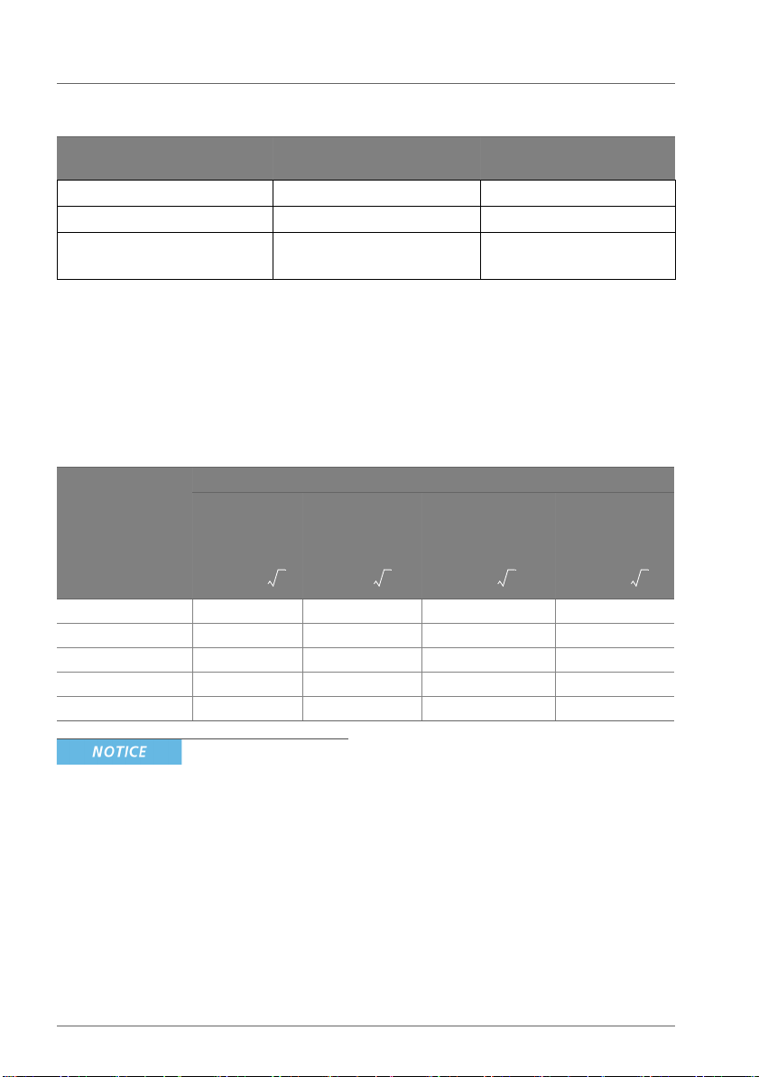
Table 4 Recommended separation distances between portable and mobile RF communica-
tions equipment and the HAMILTON-T1 ventilator
Rated maximum
output power of
transmitter (W)
0.01 0.035 0.12 0.040 0.077
0.1 0.11 0.38 0.13 0.24
1 0.35 1.2 0.40 0.77
10 1.1 3.8 1.3 2.4
100 3.5 12 4.0 7.7
Separation distance according to frequency of transmitter (m)
150 kHz to 80
MHz outside
ISM bands
150 kHz to 80
MHz in ISM
bands
80 MHz to 800
MHz
800 MHz to 2.5
GHz
output power rating of the transmitter
in watts (W) according to the transmitter
• These guidelines may not apply in all
situations. Electromagnetic propagation
is affected by absorption and reflection
from structures, objects, and people.
• For transmitters rated at a maximum
output power not listed above, the
recommended separation distance d in
meters (m) can be determined using the
equation applicable to the frequency of
the transmitter, where P is the maximum
manufacturer.
• At 80 MHz and 800 MHz, the separation
distance for the higher frequency range
applies.
• The ISM (industrial, scientific and
medical) bands between 150 kHz and
80 MHz are 6.765 MHz to 6.795 MHz;
13.553 MHz to 13.567 MHz; 26.957
MHz to 27.283 MHz; and 40.66 MHz to
40.70 MHz.
6 English | 627049/01
Page 7

• An additional factor of 10/3 has been
incorporated into the formulas used in
calculating the recommended
separation distance for transmitters in
the ISM frequency bands between 150
kHz and 80 MHz and in the frequency
range 80 MHz to 2.5 GHz to decrease
the likelihood that mobile/portable
communications equipment could cause
interference if it is inadvertently brought
into patient areas.
Table 5 Guidance and manufacturer’s
declaration electromagnetic
emissions (RTCA/DO-160F)
Description Standard Criteria
Maximum
level of conducted RF
interference Power line
Maximum
level of radiated RF interference
RTCA/DO-160F
Section 21
RTCA/DO-160F
Section 21
Category M
Category M
Table 6 Guidance and manufacturer’s
declaration electromagnetic immunity (RTCA/DO-160F)
Description Standard Criteria
Electrostatic
discharge
Magnetic
fields
induced into
equipment
Radio Frequency Susceptibility
Radiated
Standard
RTCA/DO-160F
Section 25
RTCA/DO-160F
19.3.1
RTCA/DO-160F
Section 20.5
Category A
Category BC
Category R
28 V DC
Table 6 Guidance and manufacturer’s
declaration electromagnetic immunity (RTCA/DO-160F)
Description Standard Criteria
Radio Frequency Susceptibility
Conducted,
BCI
RTCA/DO-160F
Section 20.4
Category R
28 V DC
Table 7 Guidance and manufacturer’s
declaration electromagnetic immunity (RTCA/DO-160F)
Description Standard Criteria
Normal surge
voltage (DC
Abnormal
operating
conditions
(DC) -> Voltage steady
stat
Low voltage
conditions
(DC)
Abnormal
surge voltage (DC)
Voltage spike RTCA/DO-160F
DC input
power leads
RTCA/DO-160F
Section 16.6.1.4
RTCA/DO-160F
Section 16.6.2.1
RTCA/DO-160F
Section 16.6.2.2
RTCA/DO-160F
Section 16.6.2.4
Section 17
RTCA/DO-160F
Section 18.3.1
Category A
28 V DC
Category A
28 V DC
Category A
28 V DC
Category A
28 V DC
Category A
28 V DC
Category B
Hamilton Medical | HAMILTON-T1 EMC Declarations 7
Page 8

EMC declarations IEC 60601-1-2:2007, 3rd edition
8 English | 627049/01
Page 9

HAMILTON-T1 EMC
EMC declarations IEC 60601-1-2:2014, 4th edition
Declarations
This guide provides information about
EMC declarations. It is designed for use
together with your ventilator Operator’s
Manual, and refers to information
provided there.
Functioning of the device may be impaired
by the operation of high-frequency
surgical equipment, microwaves,
shortwaves, or strong magnetic fields in
close proximity.
The HAMILTON-T1 ventilator is intended
for use in the electromagnetic environment specified in Tables 5, 6, and 12;
essential performance is not affected.
The customer or the user of the
HAMILTON-T1 ventilator should ensure
that it is used in such an environment.
• To prevent interrupted operation of the
ventilator due to electromagnetic interference, avoid using it adjacent to or
stacking other devices on it. If adjacent
or stacked use is necessary, verify the
ventilator’s normal operation in the configuration in which it will be used.
• To prevent increased emissions,
decreased immunity, or interrupted
operation of the ventilator or any accessories, use only accessories or cables
that are expressly stated in this manual.
• Use of accessories, transducers, and
cables other than those specified or provided by the manufacturer of this equipment could result in increased
electromagnetic emissions or decreased
electromagnetic immunity of this equipment and result in improper operation.
• Portable RF communications equipment
(including peripherals such as antenna
cables and external antennas) should be
used no closer than 30 cm (12 inches) to
any part of the HAMILTON-T1 ventilator,
including cables specified by the manufacturer. Otherwise, degradation of the
performance of this equipment could
result.
Hamilton Medical | HAMILTON-T1 EMC Declarations 9
Page 10
EMC declarations IEC 60601-1-2:2014, 4th edition
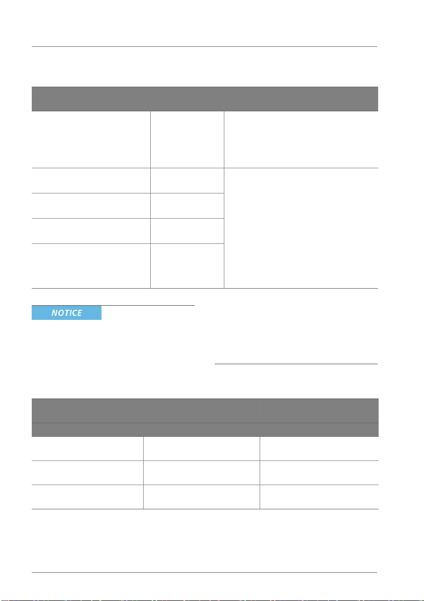
Table 5 Guidance and manufacturer's declaration – electromagnetic emissions
(IEC 60601-1-2:2014)
Emissions test Compliance Electromagnetic environment
guidance
RF emissions
CISPR 11
Group 1 The HAMILTON-T1 ventilator uses
RF energy only for its internal function.
Therefore, its RF emissions are very low
and are not likely to cause any interference in nearby electronic equipment.
RF emissions
CISPR 11, conducted
RF emissions
CISPR 11, radiated
Harmonic emissions
IEC 61000-3-2
Voltage fluctuations/flicker
emissions
IEC 61000-3-3
Class B The emissions characteristics of this
equipment make it suitable for use in
Class B
Class A
industrial areas and hospitals (CISPR 11
class A). If it is used in a residential environment (for which CISPR 11 class B is
normally required) this equipment
might not offer adequate protection to
Complies
radio-frequency communication
services. The user might need to take
mitigation measures, such as relocating
or re-orienting the equipment.
frequency range applies.
• These guidelines may not apply in all
• UT is the AC mains voltage prior to
application of the test level.
• At 80 MHz and 800 MHz, the higher
situations. Electromagnetic propagation
is affected by absorption and reflection
from structures, objects, and people.
Table 6 Guidance and manufacturer's declaration – electromagnetic immunity
(IEC 60601-1-2:2014)
Immunity test IEC 60601-1-2:2014
Test level
For electromagnetic environment guidance, see Table 8
Electrostatic discharge (ESD)
IEC 61000-4-2
Electrical fast transient/burst
IEC 61000-4-4
Surge
IEC 61000-4-5:
±8 kV contact
±2 kV, ±4 kV, ±8 kV, ±15 kV air
±2 kV for power supply lines
±1 kV for input/output lines
±1 kV line(s) to line(s)
±2 kV line(s) to earth
IEC 60601-1-2:2014
Compliance level
±2 kV, ±4 kV, ±8 kV contact
±2 kV, ±4 kV, ±8 kV, ±15 kV air
±2 kV for power supply lines
±1 kV for input/output lines
±1 kV line(s) to line(s)
±2 kV (line(s) to earth
10 English | 627049/01
Page 11
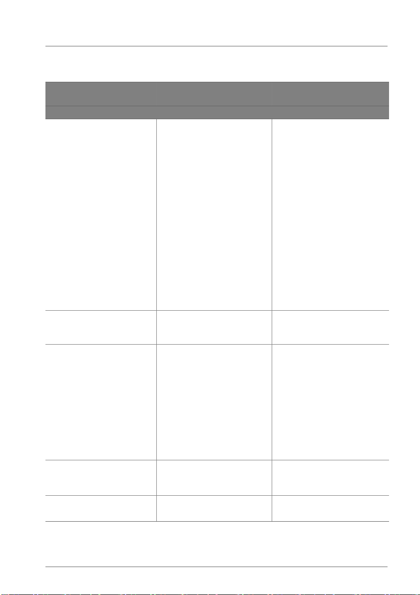
Table 6 Guidance and manufacturer's declaration – electromagnetic immunity
(IEC 60601-1-2:2014)
(cont.)
Immunity test IEC 60601-1-2:2014
For electromagnetic environment guidance, see Table 8
Voltage dips, short interruptions, and voltage variations
on power supply input lines
IEC 61000-4-11
Power frequency (50/60 Hz)
magnetic field
IEC 61000-4-8
Conducted RF
IEC 61000-4-6:
Test level
Cycle 0.5
U
=0%
T
Phase=0°, 45°, 90°, 135°,
180°, 225°, 270°, 315°.
Cycle 1
U
=0%
T
Phase=0°
Cycle 25 (50Hz)
Cycle 30 (60Hz)
U
= 70%
T
Phase=0°
Cycle 250 (50Hz)
Cycle 300 (60Hz)
U
=0%
T
Phase=0°
30 A/m 30 A/m
3Vrms
150 kHz to 80 MHz outside
ISM bands
IEC 60601-1-2:2014
Compliance level
Cycle 0.5
U
=0%
T
Phase=0°, 45°, 90°, 135°, 180°,
225°, 270°, 315°.
Cycle 1
U
=0%
T
Phase=0°
Cycle 25 (50Hz)
Cycle 30 (60Hz)
U
= 70%
T
Phase=0°
Cycle 250 (50Hz)
Cycle 300 (60Hz)
U
=0%
T
Phase=0°
6 Vrms
150 kHz to 80 MHz outside
ISM bands
6Vrms
150 kHz to 80 MHz in ISM
bands
Radiated RF
IEC 61000-4-3
3 V/m
80 MHz - 2.7 GHz
80 % AM at 1 kHz
Immunity to proximity fields
IEC 61000-4-3
Hamilton Medical | HAMILTON-T1 EMC Declarations 11
See Table 7 See Table 7
6 Vrms
150 kHz to 80 MHz in ISM
bands
10 V/m
80 MHz - 3 GHz
80 % AM at 1 kHz
Page 12

EMC declarations IEC 60601-1-2:2014, 4th edition
Table 7 Compliance and test levels, Radiated RF IEC 61000-4-3
Te st
frequency
Band
(MHz)
Service Modulation Maximum
(MHz)
385 380-390 TETRA 400 Pulse
450 430-470 GMRS 460, FRS
710 704-787 LTE Band 13, 17 Pulse
745
780
810 800-960 GSM 800/900,
870
930
1720 1700-1990 GSM 1800,
1845
1970
2450 2400-2570 Bluetooth,
5240 5100-5800 WLAN 802.11
5500
5785
460
TETRA 800, iDEN
820, CDMA 850,
LTE Band 5
CDMA 1900,
GSM 1900,
DECT, LTE Band
1, 3, 4, 25,
UMTS
WLAN, 802.11
b/g/n, RFID
2450, LTE Band
7
a/n
modulation
18 Hz
FM ± 5 kHz
deviation
1kHz sine
modulation
217 Hz
Pulse
modulation
18 Hz
Pulse
modulation
217 Hz
Pulse
modulation
217 Hz
Pulse
modulation
217 Hz
Distance
power
(m)
(W)
1.8 0.3 27
20.328
0.2 0.3 9
20.328
20.328
20.328
0.2 0.3 9
Immunity
test level
(V/m)
12 English | 627049/01
Page 13
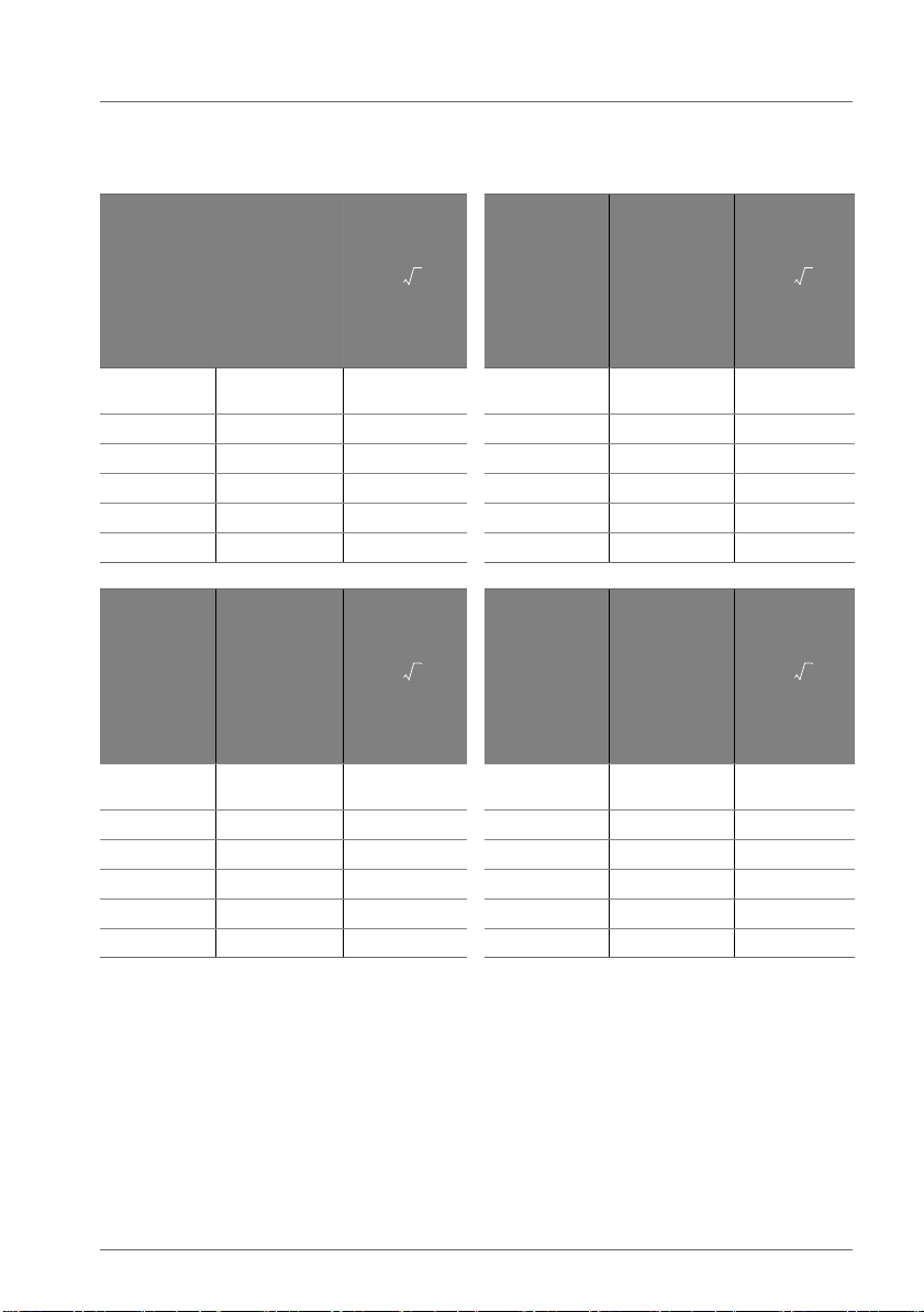
Table 8 Recommended separation distances between portable and mobile RF communica-
d
6
E
--- P=
d
6
E
--- P=
d
6
E
--- P=
d
6
E
--- P=
tions equipment and the HAMILTON-T1 ventilator
Rated
maximum
output
power of
transmitter
P(W)
0.01 27 0.3 0.01 28 0.3
0.1 27 0.3 0.1 28 0.3
1270.3 1 280.3
10 27 0.7 10 28 0.68
100 27 2.22 100 28 2.14
Electric field
strength
E(V/m) at
frequency
band
380 to 390
MHz
Minimum
separation
distance (m)
or 0.3,
whichever is
greater
Rated
maximum
output power
of transmitter
P(W)
Electric field
strength
E(V/m) at
frequency
band
430 to 470
MHz
Minimum
separation
distance (m)
or 0.3,
whichever is
greater
Rated
maximum
output
power of
transmitter
P(W)
Electric field
strength
E(V/m) at
frequency
band
704 to 787
MHz
Minimum
separation
distance (m)
or 0.3,
whichever is
greater
Rated
maximum
output power
of transmitter
P(W)
Electric field
strength
E(V/m) at
frequency
band
800 to 960
MHz
0.01 9 0.3 0.01 28 0.3
0.1 9 0.3 0.1 28 0.3
1 9 0.67 1 28 0.3
10 9 2.11 10 28 0.68
100 9 6.67 100 28 2.14
Minimum
separation
distance (m)
or 0.3,
whichever is
greater
Hamilton Medical | HAMILTON-T1 EMC Declarations 13
Page 14
EMC declarations IEC 60601-1-2:2014, 4th edition
d
6
E
--- P=
d
6
E
--- P=
d
6
E
--- P=
d
6
E
--- P=
Rated
maximum
output
power of
transmitter
P(W)
Electric field
strength
E(V/m) at
frequency
band
1700 to 1990
MHz
Minimum
separation
distance (m)
or 0.3,
whichever is
greater
Rated
maximum
output power
of transmitter
P(W)
Electric field
strength
E(V/m) at
frequency
band
2400 to 2570
MHz
Minimum
separation
distance (m)
or 0.3,
whichever is
greater
0.01 28 0.3 0.01 28 0.3
0.1 28 0.3 0.1 28 0.3
1280.3 1280.3
10 28 0.68 10 28 0.68
100 28 2.14 100 28 2.14
Rated
maximum
output
power of
transmitter
P(W)
Electric field
strength
E(V/m) at
frequency
band
80 MHz to
2.7 GHz
Minimum
separation
distance (m)
or 0.3,
whichever is
greater
Rated
maximum
output power
of transmitter
P(W)
Electric field
strength
E(V/m) at
frequency
band
5.1 to 5.8 GHz
Minimum
separation
distance (m)
or 0.3,
whichever is
greater
0.01 10 0.3 0.01 9 0.3
0.1 10 0.3 0.1 9 0.3
1100.6 1 90.67
10 10 1.9 10 9 2.11
100 10 6 100 9 6.67
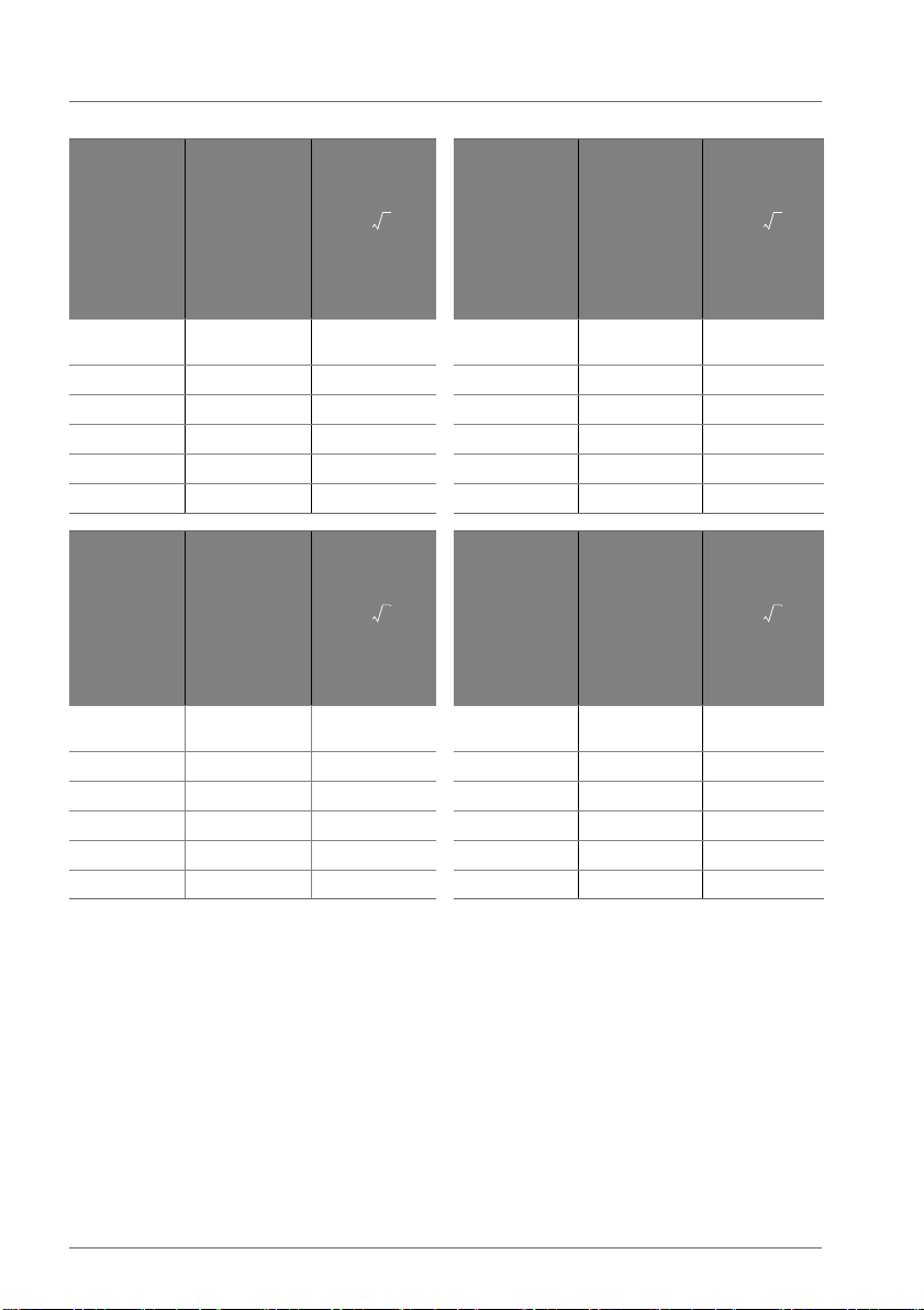
The HAMILTON-T1 is intended for use in
an electromagnetic environment in which
radiated RF disturbances are controlled.
The customer or the user of the ventilator
can help prevent electromagnetic interference by maintaining a minimum distance
between portable and mobile RF communications equipment (transmitters) and the
ventilator, according to the maximum output power of the communications equipment.
14 English | 627049/01
Page 15

Table 9 Guidance and manufacturer’s
declaration electromagnetic
emissions (RTCA/DO-160F)
Table 11 Guidance and manufacturer’s
declaration electromagnetic immunity (RTCA/DO-160F)
Description Standard Criteria
Maximum
level of conducted RF
interference Power line
Maximum
level of radiated RF interference
RTCA/DO-160F
Section 21
RTCA/DO-160F
Section 21
Category M
Category M
Table 10 Guidance and manufacturer’s
declaration electromagnetic immunity (RTCA/DO-160F)
Description Standard Criteria
Electrostatic
discharge
Magnetic
fields
induced into
equipment
Radio Frequency Susceptibility
Radiated
Standard
Radio Frequency Susceptibility
Conducted,
BCI
RTCA/DO-160F
Section 25
RTCA/DO-160F
19.3.1
RTCA/DO-160F
Section 20.5
RTCA/DO-160F
Section 20.4
Category A
Category BC
Category R
28 V DC
Category R
28 V DC
Description Standard Criteria
Normal surge
voltage (DC
Abnormal
operating
conditions
(DC) -> Voltage steady
stat
Low voltage
conditions
(DC)
Abnormal
surge voltage (DC)
Voltage spike RTCA/DO-160F
DC input
power leads
RTCA/DO-160F
Section 16.6.1.4
RTCA/DO-160F
Section 16.6.2.1
RTCA/DO-160F
Section 16.6.2.2
RTCA/DO-160F
Section 16.6.2.4
Section 17
RTCA/DO-160F
Section 18.3.1
Category A
28 V DC
Category A
28 V DC
Category A
28 V DC
Category A
28 V DC
Category A
28 V DC
Category B
Hamilton Medical | HAMILTON-T1 EMC Declarations 15
Page 16
EMC declarations IEC 60601-1-2:2014, 4th edition
• These guidelines may not apply in all
situations. Electromagnetic propagation
is affected by absorption and reflection
from structures, objects, and people.
• For transmitters rated at a maximum
output power not listed above, the
recommended separation distance d in
meters (m) can be determined using the
equation applicable to the frequency of
the transmitter, where P is the maximum
output power rating of the transmitter
in watts (W) according to the transmitter
manufacturer.
Table 12 FDA additional tests
FDA Excerpts Related to EMI FDA Excerpts Related to EMI
test level
FDA Excerpts Related to
EMI compliance level
Slow Sags and Surges 150/120/90 Vrms 500 ms 150/120/90 Vrms 500 ms
Quasi-static electric fields 2000 V/m; 0.5 Hz 2000 V/m; 0.5 Hz
Steady-state voltage 95 V / 60 Hz
132 V / 60 Hz
95 V / 60 Hz
132 V / 60 Hz
16 English | 627049/01
Page 17

Hamilton Medical | HAMILTON-T1 EMC Declarations 17
Page 18

EMC declarations IEC 60601-1-2:2014, 4th edition
18 English | 627049/01
Page 19
HAMILTON-T1 EMC
EMC RFID declarations, AIM Standard Rev. 1.00 2016-08-22
Declarations
This guide provides information about
EMC RFID declarations. It is designed for
use together with your ventilator
Operator’s Manual, and refers to
information provided there.
Table 13 Guidance and manufacturer's declaration – RFID immunity (IEC 61000-4-3)
Immunity test Test frequency Test level Compliance level
Immunity to RFID fields
(Proximity cards)
ISO/IEC 14443-3 (Type A)
Immunity to RFID fields
(Proximity cards)
ISO/IEC 14443-4 (Type B)
Immunity to RFID fields
(Vicinity cards)
ISO/IEC 15693
(ISO 18000-3, Mode 1)
Immunity to RFID fields
(Item management)
ISO/IEC 18000-7
Immunity to RAIN fields
(Item management)
ISO/IEC 18000-63, Type C
Immunity to 2.45 GHz RFID fields
(Item management)
ISO/IEC 18000-4, Mode 1
13.56 MHz
13.56 MHz 5 A/m 5 A/m
13.56 MHz 5 A/m 5 A/m
433.92 MHz 3 V/m 3 V/m
860 - 960 MHz 54 V/m 54 V/m
2.45 GHz 54 V/m 54 V/m
5 A/m 5 A/m
Hamilton Medical | HAMILTON-T1 EMC Declarations 19
Page 20

Hamilton Medical AG
Via Crusch 8, 7402 Bonaduz,
Switzerland
+41 58 610 10 20
www.hamilton-medical.com
PN 627049/01 ©2020 Hamilton Medical AG. Printed in Switzerland.
 Loading...