

Page 1

EMC Enterprise Storage
EMC Fibre Channel Storage System
Model FC4700
CONFIGURATION PLANNING GUIDE
P/N 014003016-A03
EMC Corporation 171 South Street, Hopkinton, MA 01748-9103
Corporate Headquarters
: (508) 435-1000, (800) 424-EMC2
Fax
: (508) 435-5374
Service
: (800) SVC-4EMC
Page 2

Copyright © 2000, 2001 EMC Corporation. All rights reserved.
Printed October 2001
EMC believes the information in this publication is accurate as of its publication date. However, the
information is subject to change without notice.
THE INFORMATION IN THIS PUBLICATION IS PROVIDED “AS IS.” EMC CORPORATION MAKES NO
REPRESENTATIONS OR WARRANTIES OF ANY KIND WITH RESPECT TO THE INFORMATION IN THIS
PUBLICATION, AND SPECIFICALLY DISCLAIMS IMPLIED WARRANTIES OF MERCHANTABILITY OR
FITNESS FOR A PARTICULAR PURPOSE.
Use, copying, and distribution of any EMC software described in this publication require an applicable
software license.
Trademark Information
EMC2, EMC, Navisphere, CLARiiON, MOSAIC:2000, and Symmetrix are registered trademarks and EMC Enterprise Storage, The Enterprise Storage
Company, The EMC Effect, Connectrix, EDM, SDMS, SRDF, Timefinder, PowerPath, InfoMover, FarPoint, EMC Enterprise Storage Network, EMC
Enterprise Storage Specialist, EMC Storage Logix, Universal Data Tone, E-Infostructure, Access Logix, Celerra, SnapView, and MirrorView are
trademarks of EMC Corporation.
All other trademarks mentioned herein are the property of their respective owners.
ii
EMC Fibre Channel Storage System Model FC4700 Configuration Planning Guide
Page 3

Contents
Preface..............................................................................................................................ix
Chapter 1 About Fibre Channel FC4700 Storage Systems and
Storage Networks
Introducing Fibre Channel Storage Systems.................................1-2
Fibre Channel Background..............................................................1-3
Fibre Channel Storage Components ..............................................1-4
Server Component (Host Bus Adapter Driver Package with
Software).....................................................................................1-4
Interconnect Components ........................................................1-4
Storage Component (Storage Systems, SPs, and Other
Hardware)...................................................................................1-7
Types of Storage-System Installations ...........................................1-8
About Switched Shared Storage and SANs (Storage Area
Networks) ..........................................................................................1-9
Storage Groups.........................................................................1-10
Storage-System Hardware......................................................1-13
Chapter 2 RAID Types and Tradeoffs
Introducing RAID.............................................................................2-2
Disk Striping...............................................................................2-2
Mirroring.....................................................................................2-2
RAID Groups and LUNs ..........................................................2-3
RAID Types........................................................................................2-4
RAID 5 Group (Individual Access Array) .............................2-4
RAID 3 Group (Parallel Access Array)...................................2-5
RAID 1 Mirrored Pair................................................................2-7
RAID 0 Group (Nonresident Array).......................................2-7
EMC Fibre Channel Storage System Model FC4700 Configuration Planning Guide
iii
Page 4

Contents
RAID 1/0 Group (Mirrored RAID 0 Group).........................2-8
Individual Disk Unit .................................................................2-9
Hot Spare....................................................................................2-9
RAID Benefits and Tradeoffs.........................................................2-12
Performance .............................................................................2-13
Storage Flexibility....................................................................2-14
Data Availability and Disk Space Usage..............................2-14
Guidelines for RAID Groups........................................................2-17
Sample Applications for RAID Types..........................................2-19
Chapter 3 About MirrorView Remote Mirroring Software
What Is EMC MirrorView Software?.............................................3-2
MirrorView Features and Benefits .................................................3-4
Provision for Disaster Recovery with Minimal Overhead..3-4
Local High Availability ............................................................3-4
Cross Mirroring..........................................................................3-4
Integration with EMC SnapView LUN Copy Software.......3-5
How MirrorView Handles Failures ...............................................3-5
Primary Image Failure..............................................................3-5
Secondary Image Failure..........................................................3-6
MirrorView Example........................................................................3-7
MirrorView Planning Worksheet....................................................3-9
Chapter 4 About SnapView Snapshot Copy Software
What Is EMC SnapView Software?................................................4-2
Snapshot Components..............................................................4-3
Sample Snapshot Session.................................................................4-4
Snapshot Planning Worksheet........................................................4-5
Chapter 5 Planning File Systems and LUNs
Multiple Paths to LUNs...................................................................5-2
Sample Shared Switched Installation ............................................5-3
Sample Unshared Direct Installation.............................................5-7
Planning Applications, LUNs, and Storage Groups....................5-8
Application and LUN Planning ..............................................5-8
Application and LUN Planning Worksheet ..........................5-9
LUN and Storage Group Planning Worksheet ...................5-10
LUN Details Worksheet..........................................................5-13
iv
EMC Fibre Channel Storage System Model FC4700 Configuration Planning Guide
Page 5

Chapter 6 Storage-System Hardware
Hardware for FC4700 Storage Systems.........................................6-3
Storage Hardware — Rackmount DPE-Based Storage
Systems....................................................................................... 6-3
Disks............................................................................................6-4
Storage Processor (SP)..............................................................6-5
Planning Your Hardware Components ........................................ 6-8
Components for Shared Switched Storage............................6-8
Components for Shared-or-Clustered Direct Storage .........6-8
Components for Unshared Direct Storage............................ 6-8
Hardware Data Sheets..................................................................... 6-9
DPE Data Sheet.......................................................................... 6-9
DAE Data Sheet....................................................................... 6-11
Cabinets for Rackmount Enclosures............................................ 6-12
Cable and Configuration Guidelines ..........................................6-13
Hardware Planning Worksheets ..................................................6-13
Cable Planning Template....................................................... 6-14
Sample Cable Templates........................................................6-16
Hardware Component Worksheet........................................6-17
Chapter 7 Storage-System Management
Introducing Navisphere Management Software......................... 7-2
Using Navisphere Manager Software........................................... 7-3
Storage Management Worksheet ................................................... 7-4
Contents
Index ................................................................................................................................i-1
EMC Fibre Channel Storage System Model FC4700 Configuration Planning Guide
v
Page 6

Contents
vi
EMC Fibre Channel Storage System Model FC4700 Configuration Planning Guide
Page 7

Figures
1-1 Cutaway View of FC4700 Storage System ................................................ 1-2
1-2 Nodes - Initiator and Target ....................................................................... 1-3
1-3 Switch Topology (Port to Port) ................................................................... 1-5
1-4 A Switch Zone ............................................................................................... 1-6
1-5 16-Port Switch, Back View .......................................................................... 1-7
1-6 Model 4700 DPE ............................................................................................ 1-7
1-7 Types of Storage-System Installation ........................................................ 1-8
1-8 Components of a SAN ................................................................................. 1-9
1-9 Sample Shared Storage Configuration .................................................... 1-11
1-10 Data Access Control with Shared Storage .............................................. 1-12
1-11 Storage System with DPE and Three DAEs ........................................... 1-13
2-1 Multiple LUNs in a RAID Group ............................................................... 2-3
2-2 RAID 5 Group ............................................................................................... 2-5
2-3 RAID 3 Group ............................................................................................... 2-6
2-4 RAID 1 Mirrored Pair .................................................................................. 2-7
2-5 RAID 1/0 Group ........................................................................................... 2-9
2-6 How a Hot Spare Works ............................................................................ 2-11
2-7 Disk Space Usage in the RAID Configuration ....................................... 2-16
3-1 Sites with MirrorView Primary and Secondary Images ......................... 3-3
3-2 Sample MirrorView Configuration ............................................................ 3-7
4-1 SnapView Operations Model ...................................................................... 4-3
4-2 How a Snapshot Session Starts, Runs, and Stops .................................... 4-4
5-1 Sample Shared Switched Storage Configuration ..................................... 5-4
5-2 Unshared Direct Storage Example ............................................................. 5-7
6-1 Types of Storage-System Installation ........................................................ 6-2
6-2 DPE Storage-System Components — Rackmount Model ...................... 6-3
6-3 Rackmount Storage System with DPE and DAEs ................................... 6-4
6-4 Disk Modules and Module IDs .................................................................. 6-5
6-5 Shared Storage Systems ............................................................................... 6-6
6-6 Cable Planning Template — FC4700 Shared Storage System .............. 6-14
EMC Fibre Channel Storage System Model FC4700 Configuration Planning Guide
vii
Page 8

Figures
6-7 Sample Shared Storage Installation .......................................................... 6-16
7-1 Sample Shared Switched Environment with Manager ........................... 7-3
viii
EMC Fibre Channel Storage System Model FC4700 Configuration Planning Guide
Page 9

Audience for the Manual
Preface
This planning guide provides an overview of Fibre Channel
disk-array storage-system models and offers useful background
information and worksheets to help you plan.
Please read this guide
• if you are considering purchase of an EMC FC-series (Fibre
Channel) FC4700 disk-array storage system and want to
understand its features; or
• before you plan the installation of a storage system.
You should be familiar with the host servers that will use the storage
systems and with the operating systems of the servers. After reading
this guide, you will be able to
• determine the best storage-system components for your
installation
• determine your site requirements
• configure storage systems correctly
EMC Fibre Channel Storage System Model FC4700 Configuration Planning Guide
ix
Page 10

Preface
Organization of the Manual
Conventions Used in This Manual
Where to Get Help Obtain technical support by calling your local sales office.
Chapter 1 Provides background information about Fibre Channel
features and explains the major types of storage.
Chapter 2 Describes the RAID Groups and the different ways they
store data.
Chapter 3 Describes the optional EMC MirrorView™ remote
mirroring software.
Chapter 4 Describes the optional EMC SnapView™ snapshot copy
software.
Chapter 5 Helps you plan your storage system software and LUNs.
Chapter 6 Explains the hardware components of storage systems.
Chapter 7 Describes storage-system management utilities.
A note presents information that is important, but not hazard-related.
If you are located outside the USA, call the nearest EMC office for
technical assistance.
For service, call:
United States: (800) 782-4362 (SVC-4EMC)
Canada: (800) 543-4782 (543-4SVC)
Worldwide: (508) 497-7901
and ask for Customer Service.
Your Comments Your suggestions will help us continue to improve the accuracy,
organization, and overall quality of the user publications. Please
e-mail us at techpub_comments@emc.com to let us know your
opinion or any errors concerning this manual.
x
EMC Fibre Channel Storage System Model FC4700 Configuration Planning Guide
Page 11

Invisible Body Tag
1
About Fibre Channel
FC4700 Storage
Systems and Storage
Networks
This chapter introduces Fibre Channel FC4700 disk-array storage
systems and storage area networks (SANs). Major sections are
• Introducing Fibre Channel Storage Systems..................................1-2
• Fibre Channel Background...............................................................1-3
• Fibre Channel Storage Components................................................1-4
• Types of Storage-System Installations.............................................1-8
• About Switched Shared Storage and SANs (Storage Area
Networks)............................................................................................1-9
About Fibre Channel FC4700 Storage Systems and Storage Networks
1-1
Page 12
About Fibre Channel FC4700 Storage Systems and Storage Networks
1
Introducing Fibre Channel Storage Systems
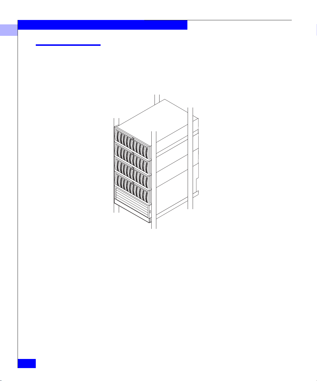
EMC Fibre Channel FC4700 disk-array storage systems provide
terabytes of disk storage capacity, high transfer rates, flexible
configurations, and highly available data at low cost.
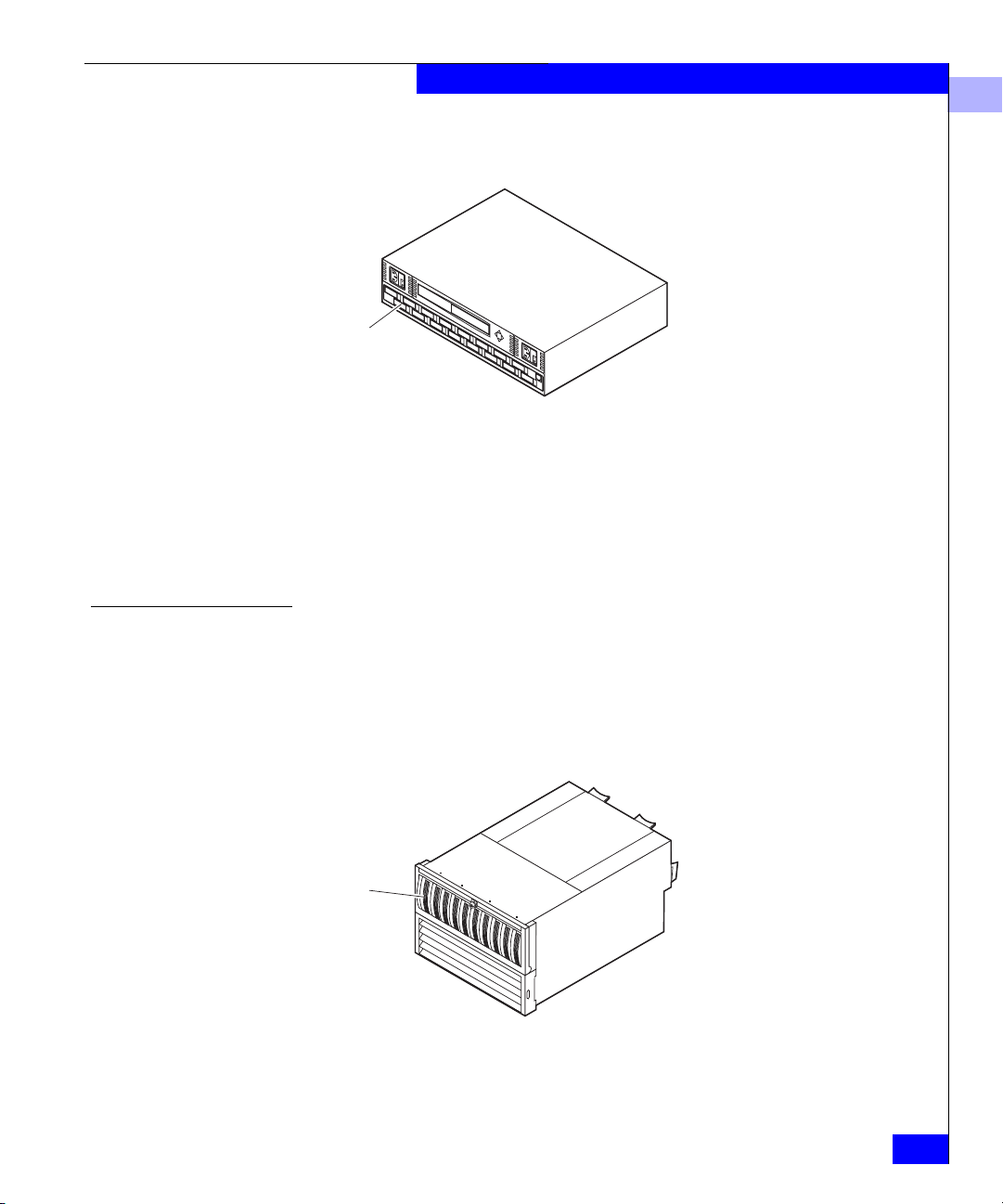
1-2
EMC1801
Figure 1-1 Cutaway View of FC4700 Storage System
A storage-system package includes a host bus adapter driver kit with
hardware and software to connect with a server, storage management
software, Fibre Channel interconnect hardware, and one or more
storage systems.
EMC Fibre Channel Storage System Model FC4700 Configuration Planning Guide
Page 13
Fibre Channel Background
Fibre Channel is a high-performance serial protocol that allows
transmission of both network and I/O channel data. It is a low level
protocol, independent of data types, and supports such formats as
SCSI and IP.
The Fibre Channel standard supports several physical topologies,
including switched fabric point-to-point and arbitrated loop (FC-AL).
The topologies used by the Fibre Channel storage systems described
in this manual are switched fabric and FC-AL.
A switch fabric is a set of point-to-point connections between nodes,
the connection being made through one or more Fibre Channel
switches. Each node may have its own unique address, but the path
between nodes is governed by a switch. The nodes are connected by
optical cable.
A Fibre Channel arbitrated loop is a circuit consisting of nodes. Each
node has a unique address, called a Fibre Channel arbitrated loop
address. The nodes are connected by optical cables. An optical cable
can transmit data over great distances for connections that span
entire enterprises and can support remote disaster recovery systems.
About Fibre Channel FC4700 Storage Systems and Storage Networks
1
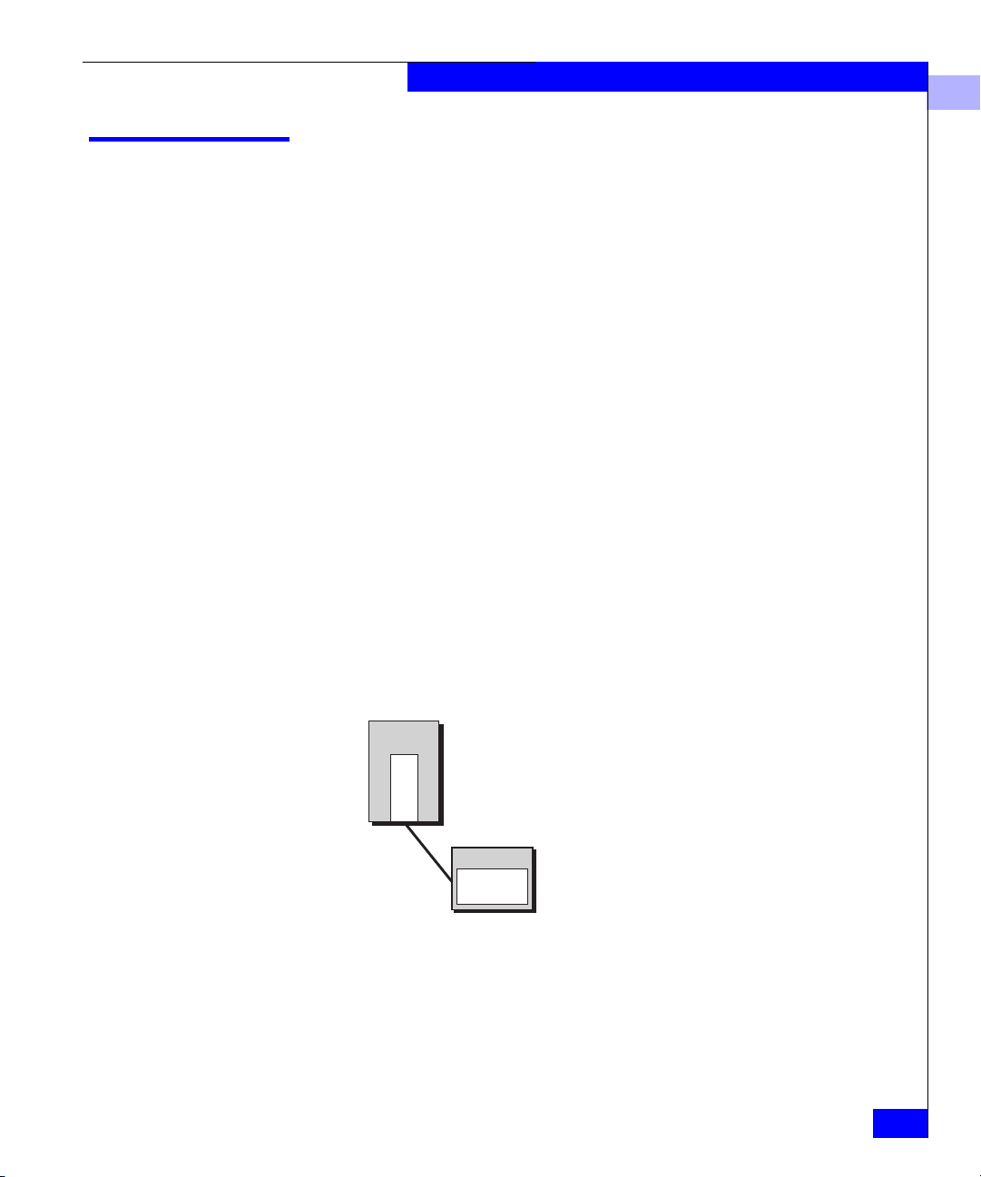
Each connected device in a switched fabric or arbitrated loop is a
server adapter (initiator) or a target (storage system). The switches
are not considered nodes.
Server Adapter (initiator)
Node
Adapter
Storage System (target)
Connection
Figure 1-2 Nodes - Initiator and Target
Node
EMC1802
Fibre Channel Background
1-3
Page 14

About Fibre Channel FC4700 Storage Systems and Storage Networks
1
Fibre Channel Storage Components
A Fibre Channel storage system has three main components:
• Server component (host bus adapter driver package with adapter
and software)
• Interconnect components (cables based on Fibre Channel
standards, and switches)
• Storage component (storage system with storage processors —
SPs — and power supply and cooling hardware)
Server Component (Host Bus Adapter Driver Package with Software)
The host bus adapter driver package includes a host bus adapter and
support software. The adapter is a printed-circuit board that slides
into an I/O slot in the server’s cabinet. It transfers data between
server memory and one or more disk-array storage systems over
Fibre Channel — as controlled by the support software (adapter
driver).
Interconnect Components
1-4
EMC Fibre Channel Storage System Model FC4700 Configuration Planning Guide
One or more servers can use a storage system. For high availability —
in event of an adapter failure — a server can have two adapters.
Server
Adapter
Adapter
EMC1803
Depending on your server type, you may have a choice of adapters.
The adapter is designed for a specific kind of bus; for example, a PCI
bus or SBUS. Any adapter you choose must support optical cable.
The interconnect components include the optical cables between
components and any Fibre Channel switches.
The maximum length of optical cable between server and switch or
storage system is 500 meters (1,640 feet) for 62.5-micron multimode
cable or 10 kilometers (6.2 miles) for 9-micron single-mode cable.
Page 15
Fibre Channel Switches
About Fibre Channel FC4700 Storage Systems and Storage Networks
1
With extenders, optical cable can span up to 40 kilometers (25 miles)
or more. This ability to span great distances is a major advantage of
optical cable.
Details on cable lengths and rules appear later in this manual.
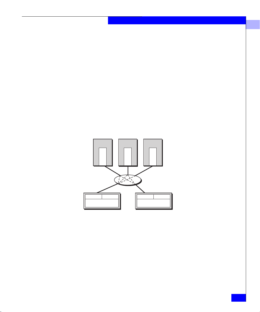
A Fibre Channel switch, which is required for switched shared
storage (a storage area network, SAN), connects all the nodes cabled
to it using a fabric topology. A switch adds serviceability and
scalability to any installation; it allows on-line insertion and removal
of any device on the fabric and maintains integrity if any connected
device stops participating. A switch also provides
server-to-storage-system access control. A switch provides
point-to-point connections
You can cascade switches (connect one switch port to another switch)
for additional port connections.
Server
Adapter
SP
Storage system
To illustrate the point-to-point quality of a switch, this figure shows
just one adapter per server and one switch. Normally, such installations
include two adapters per server and two switches.
Figure 1-3 Switch Topology (Port to Port)
Server
Adapter
SP
Storage system
Server
SP
Adapter
SP
EMC1805
Fibre Channel Storage Components
1-5
Page 16
About Fibre Channel FC4700 Storage Systems and Storage Networks
1
Switch Zoning
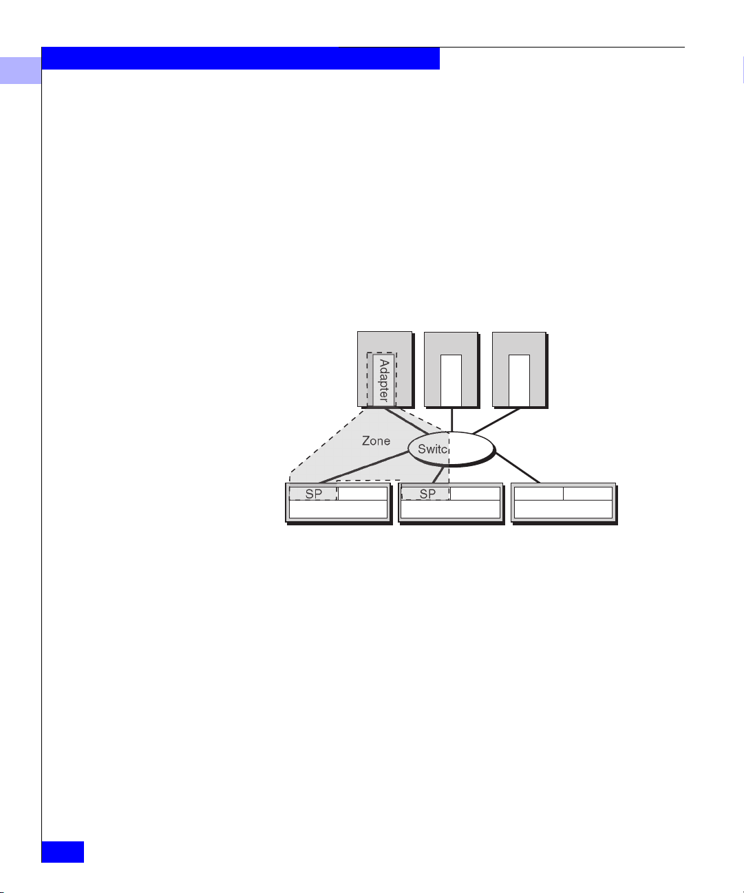
Switch zoning lets an administrator define paths between connected
nodes based on the node’s unique World Wide Name. Each zone
encloses one or more server adapters and one or more SPs. A switch
can have as many zones as it has ports.
The current connection limits are four SP ports to one adapter port
(the SPs fan in to the adapter) and 15 adapters to one SP (the SPs fan
out to the adapters). There are several zone types, including the
single-initiator type, which is the recommended type for
FC4700-series systems.
In the following figure, Server 1 has access to one SP (SP A) in storage
systems 1 and 2; it has no access to any other SP.
SP
Storage system 1
To illustrate switch zoning, this figure shows just one HBA per server
and one switch. Normally, such installations will include two HBAs per
server and two switches.
Figure 1-4 A Switch Zone
If you do not define a zone in a switch, all adapter ports connected to
the switch can communicate with all SP ports connected to the
switch. However, access to an SP does not necessarily provide access
to the SP’s storage; access to storage is governed by the Storage
Groups you create (defined later).
Fibre Channel switches are available with 16 or 8 ports. They are
compact units that fit in 2 U (3.5 inches) for the 16 port or 1 U (1.75
Server 1
Adapter
Zone
SP
Server 2
Adapter
Switch fabric
SP
Storage system 2
SP
Server 3
Adapter
SP
Storage system 3
SP
EMC1806
1-6
EMC Fibre Channel Storage System Model FC4700 Configuration Planning Guide
Page 17
About Fibre Channel FC4700 Storage Systems and Storage Networks
inches) for the 8 port. They are available to fit into a rackmount
cabinet or as small deskside enclosures.
Ports
Figure 1-5 16-Port Switch, Back View
If your servers and storage systems will be far apart, you can place
the switches closer to the servers or the storage systems, as
convenient.
A switch is technically a repeater, not a node, in a Fibre Channel loop.
However, it is bound by the same cabling distance rules as a node.
1
EMC1807
Storage Component (Storage Systems, SPs, and Other Hardware)
EMC FC-series disk-array storage systems, with their storage
processors, power supplies, and cooling hardware form the storage
component of a Fibre Channel system. The controlling unit, a Model
FC4700 disk-array processor enclosure (DPE) looks like the following
figure.
Disk
modules
EMC1808
Figure 1-6 Model 4700 DPE
DPE hardware details appear in a later chapter.
Fibre Channel Storage Components
1-7
Page 18
About Fibre Channel FC4700 Storage Systems and Storage Networks
1
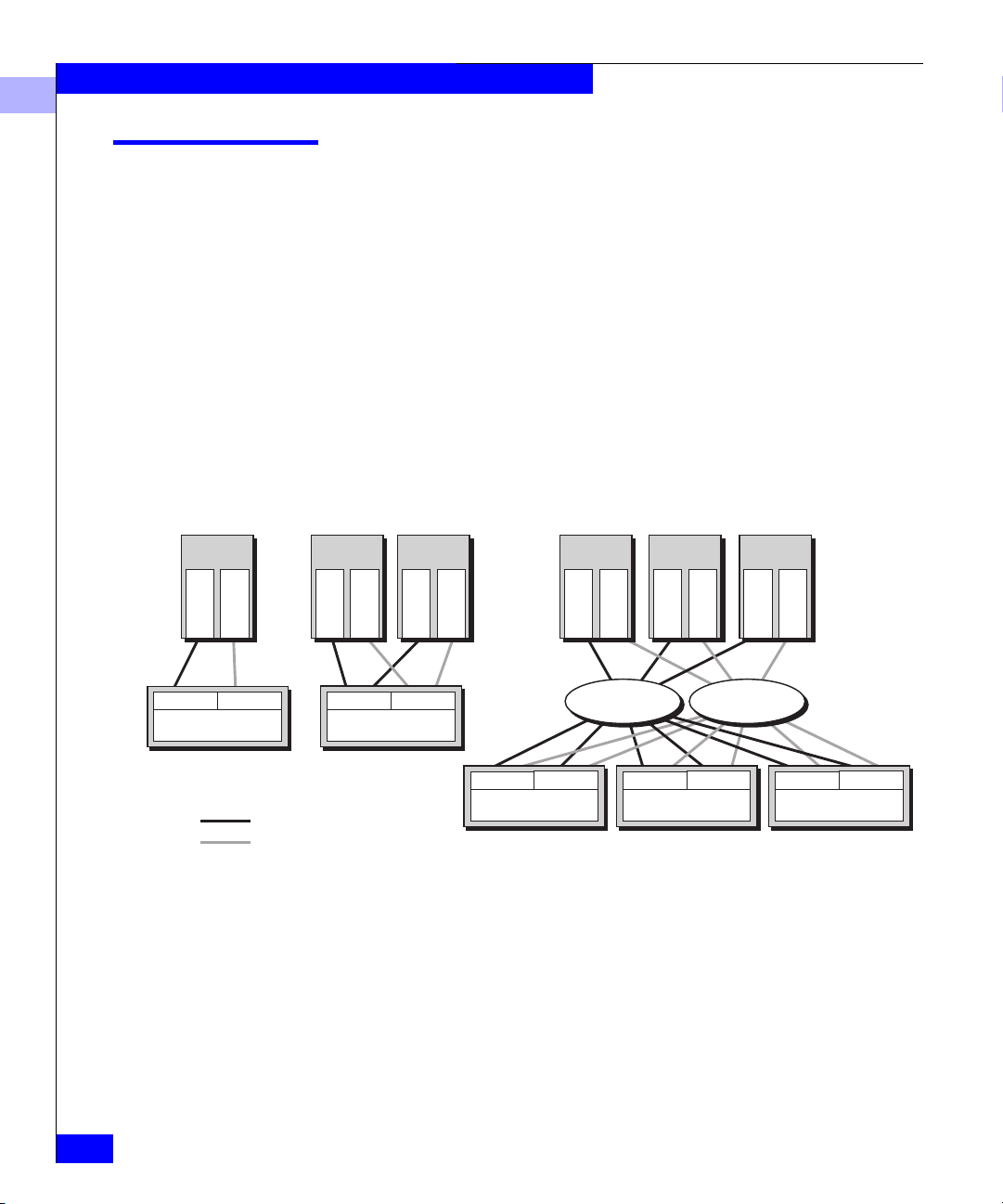
Types of Storage-System Installations
You can use a storage system in any of several types of installation:
• Unshared direct with one server is the simplest and least costly.
• Shared-or-clustered direct, with a limit of two servers, lets two
servers share storage resources with high availability.
• Shared switched, with two switch fabrics, lets two to 15 servers
share the resources of several storage systems in a storage area
network (SAN). Shared switched installations are available in
high-availability versions (two HBAs per server) or with one
HBA per server. Shared switched storage systems can have
multiple paths to each SP, providing multipath I/O for dynamic
load sharing and greater throughput.
Unshared Direct
(one or two servers)
Server
Adapter
Adapter
SP A
Storage system
Path
Path 2
SP B
1
Figure 1-7 Types of Storage-System Installation
Shared or Clustered
Direct (two servers)
Server
Adapter
SP A
Storage system
Adapter
Server
Adapter
SP B
Adapter
SP A
Storage system
Shared Switched (multiple servers,
Multiple P
Server
Adapter
Switch fabric Switch fabric
SP B
aths to SPs)
Server
Adapter
Adapter
SP A
Storage system
Adapter
SP B
Server
Adapter
Adapter
SP A
Storage system
Storage systems for any shared installation require EMC Access
TM
Logix
software to control server access to the storage-system LUNs.
The Shared-or-clustered direct installation can be either shared (that
is, use Access Logix to control LUN access) or clustered (without
Access Logix, but with operating system cluster software controlling
LUN access), depending on the hardware model. FC4700 storage
systems are shared; they include Access Logix, which means the
servers need not use cluster software to control LUN access.
SP B
EMC1809
1-8
EMC Fibre Channel Storage System Model FC4700 Configuration Planning Guide
Page 19
About Fibre Channel FC4700 Storage Systems and Storage Networks
About Switched Shared Storage and SANs (Storage Area Networks)
This section explains the features that let multiple servers share
disk-array storage systems on a SAN (storage area network).
A SAN is one or more storage devices connected to servers through
Fibre Channel switches to provide a central location for disk storage.
Centralizing disk storage among multiple servers has many
advantages, including
• highly available data
• flexible association between servers and storage capacity
• centralized management for fast, effective response to users’ data
storage needs
• easier file backup and recovery
An EMC SAN is based on shared storage; that is, the SAN requires
EMC Access Logix to provide flexible access control to
storage-system LUNs. Within the SAN, a network connection to each
SP in the storage system lets you configure and manage it.
1
Server
Adapter
Adapter
Path 1
Path 2
Figure 1-8 Components of a SAN
Switch fabric
SP A
Storage system
Fibre Channel switches can control data access to storage systems
through the use of switch zoning. With zoning, an administrator can
specify groups (called zones) of Fibre Channel devices (such as
About Switched Shared Storage and SANs (Storage Area Networks)
SP B
Server
Adapter
Adapter
Server
Adapter
Switch fabric
SP A
Storage system
SP B
Adapter
EMC1810
1-9
Page 20

About Fibre Channel FC4700 Storage Systems and Storage Networks
1
host-bus adapters, specified by worldwide name), and SPs between
which the switch fabric will allow communication.
However, switch zoning cannot selectively control data access to
LUNs in a storage system, because each SP appears as a single Fibre
Channel device to the switch fabric. So switch zoning can prevent or
allow communication with an SP, but not with specific disks or LUNs
attached to an SP. For access control with LUNs, a different solution is
required: Storage Groups.
Storage Groups
A Storage Group is one or more LUNs (logical units) within a storage
system that is reserved for one or more servers and is inaccessible to
other servers. Storage Groups are the central component of shared
storage; storage systems that are unshared do not use Storage
Groups.
When you configure shared storage, you specify servers and the
Storage Group(s) each server can read from and/or write to. The Base
Software running in each storage system enforces the
server-to-Storage Group permissions.
A Storage Group can be accessed by more than one server if all the
servers run cluster software. The cluster software enforces orderly
access to the shared Storage Group LUNs.
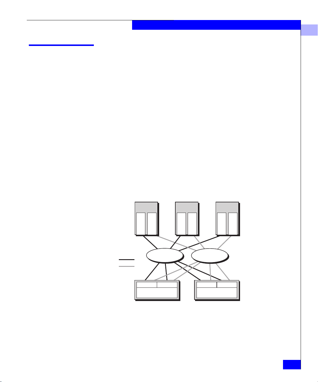
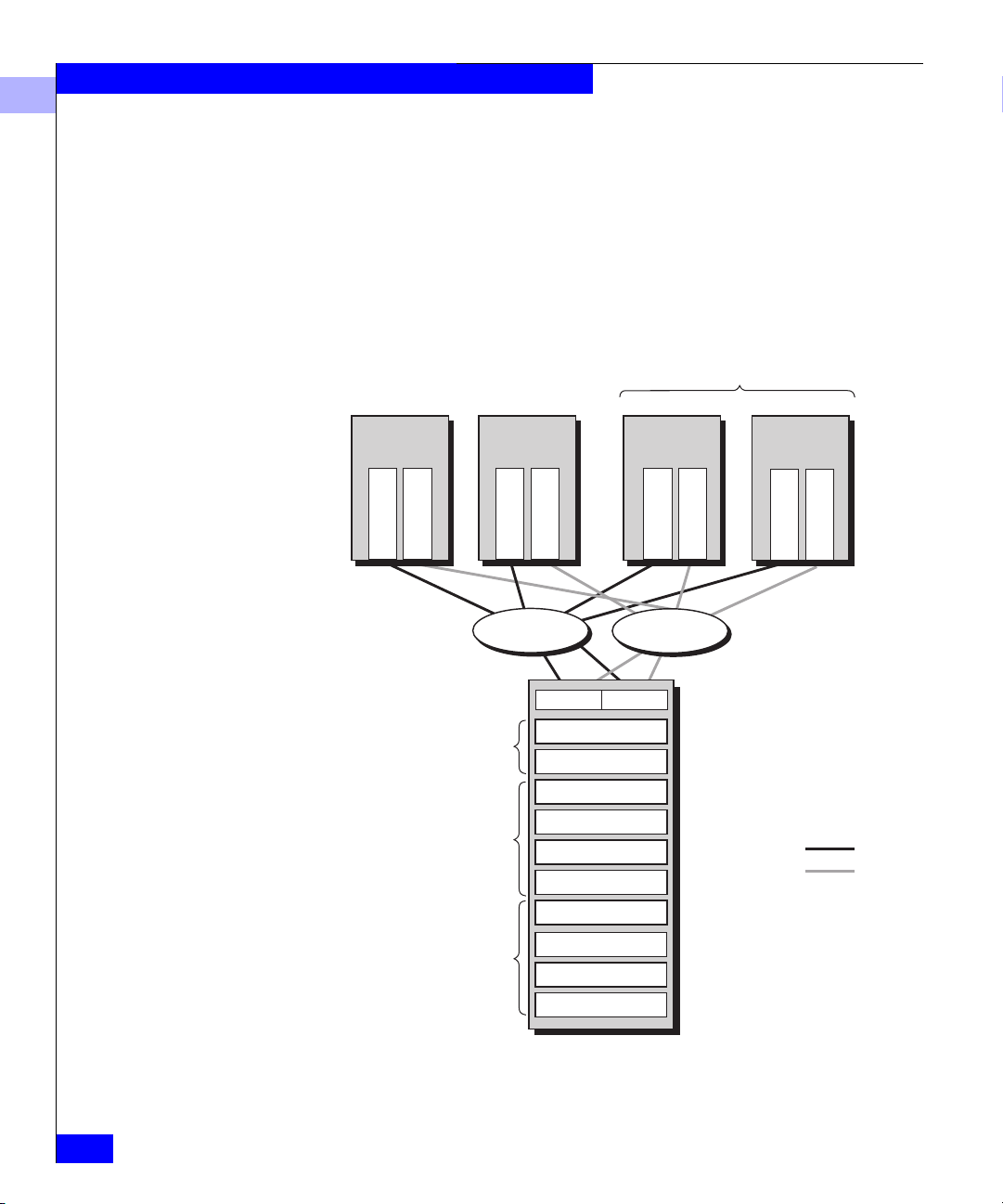
The following figure shows a simple shared storage configuration
consisting of one storage system with two Storage Groups. One
Storage Group serves a cluster of two servers running the same
operating system, and the other Storage Group serves a UNIX®
database server. Each server is configured with two independent
paths to its data, including separate host bus adapters, switches, and
SPs, so there is no single point of failure for access to its data.
1-10
EMC Fibre Channel Storage System Model FC4700 Configuration Planning Guide
Page 21
About Fibre Channel FC4700 Storage Systems and Storage Networks
1
Path
1
Path 2
Cluster Storage
Group
Database Server
Storage Group
Highly available cluster
Adapter
Adapter
Switch fabric
r
SP A SP B
Mail serve
Operating
system A
File serve
Operating
system A
Adapter
Adapter
Switch fabric
LUN
LUN
LUN
LUN
LUN
LUN
LUN
r
Database
r
serve
Operating
system
B
Adapter
Adapter
Physical storage
system with up to
100 disks per system
EMC1811
Figure 1-9 Sample Shared Storage Configuration
Access Control with Shared Storage
Access control permits or restricts a server’s access to shared storage.
Configuration access, the ability to configure storage systems, is
governed by username and password access to a configuration file on
each server.
Data access, the ability to read and write information to
storage-system LUNs, is provided by Storage Groups. During
storage-system configuration, using a management utility, the system
administrator associates a server with one or more LUNs. The
associated LUNs compose a Storage Group.
About Switched Shared Storage and SANs (Storage Area Networks)
1-11
Page 22
About Fibre Channel FC4700 Storage Systems and Storage Networks
1
Each server sees its Storage Group as if it were an entire storage
system, and never sees the other LUNs on the storage system.
Therefore, it cannot access or modify data on LUNs that are not part
of its Storage Group. However, you can define a Storage Group to be
accessible by more than one server, if, as shown above in Figure 1-9,
the servers run cluster software.
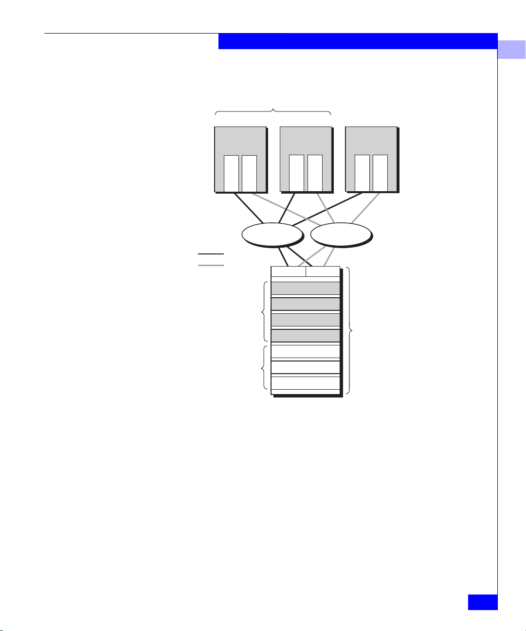
The following figure shows access control through Storage Groups.
Each server has exclusive read and write access to its designated
Storage Group.
Highly available cluster
Admin Server
Operating
system A
Adapter 00
Adapter 01
Inventory Server
Operating
system A
Adapter 02
Adapter 03
E-mail Server
Operating
system B
Adapter 04
Adapter 05
Web Server
Operating
system B
Adapter 06
Adapter 07
1-12
Switch fabric
SP A SP B
Admin Storage Group
Dedicated Data access
by adapters 00, 01
Inventory Storage Group
Dedicated Data access
by adapters 02, 03
E-mail and Web Server
Storage Sroup Shared
Data access by
adapters 04, 05, 06, 07
Figure 1-10 Data Access Control with Shared Storage
EMC Fibre Channel Storage System Model FC4700 Configuration Planning Guide
Switch fabric
LUN
LUN
LUN
LUN
LUN
LUN
LUN
LUN
LUN
LUN
Path 1
Path 2
EMC1812
Page 23
Storage-System Hardware
A Fibre Channel storage system is based on a disk-array processor
enclosure (DPE).
A DPE is a 10-slot enclosure with hardware RAID features provided
by one or two storage processors (SPs). For high availability, two SPs
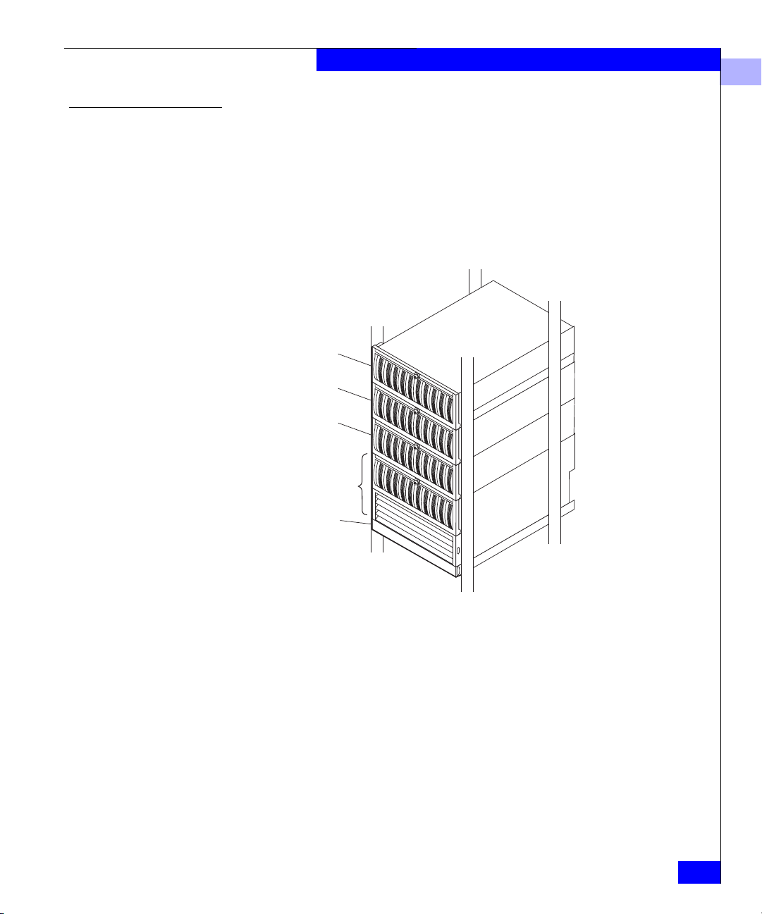
are required. In addition to its own disks, each DPE can support up to
nine 10-slot Disk Array Enclosures (DAEs) for a total of 100 disks per
storage system.
About Fibre Channel FC4700 Storage Systems and Storage Networks
1
DAE
DAE
DAE
DPE
Standby power
supply (SPS)
EMC1741
Figure 1-11 Storage System with DPE and Three DAEs
What Next? For information about RAID types and RAID tradeoffs, continue to
the next chapter.
For information on the MirrorView™ or SnapView™ software
options, go to Chapter 3 or 4.
To plan LUNs and file systems, skip to Chapter 5. For details on the
storage-system hardware, skip to Chapter 6.
About Switched Shared Storage and SANs (Storage Area Networks)
1-13
Page 24

About Fibre Channel FC4700 Storage Systems and Storage Networks
1
1-14
EMC Fibre Channel Storage System Model FC4700 Configuration Planning Guide
Page 25

Invisible Body Tag
2
RAID Types and
Tradeoffs
This chapter explains RAID types you can choose for your storagesystem LUNs. If you already know about RAID types and know
which ones you want, you can skip this background information and
go to the planning chapter (Chapter 5). Topics are
• Introducing RAID ..............................................................................2-2
• RAID Types .........................................................................................2-4
• RAID Benefits and Tradeoffs..........................................................2-12
• Guidelines for RAID Groups..........................................................2-17
• Sample Applications for RAID Types ...........................................2-19
RAID Types and Tradeoffs
2-1
Page 26

RAID Types and Tradeoffs
2
Introducing RAID
The storage system uses RAID (redundant array of independent
disks) technology. RAID technology groups separate disks into one
logical unit (LUN) to improve reliability and/or performance.
The storage system supports five RAID levels and two other disk
configurations, the individual unit and the hot spare (global spare).
You group the disks into one RAID Group by binding them using a
storage-system management utility.
Four of the RAID Groups use disk striping and two use mirroring.
Disk Striping
Mirroring
Using disk stripes, the storage-system hardware can read from and
write to multiple disks simultaneously and independently. By
allowing several read/write heads to work on the same task at once,
disk striping can enhance performance. The amount of information
read from or written to each disk makes up the stripe element size.
The stripe size is the stripe element size multiplied by the number of
disks in a group. For example, assume a stripe element size of 128
sectors (the default) and a five-disk group. The group has five disks,
so you would multiply five by the stripe element size of 128 to yield a
stripe size of 640 sectors.
The storage system uses disk striping with most RAID types.
Mirroring maintains a copy of a logical disk image that provides
continuous access if the original image becomes inaccessible. The
system and user applications continue running on the good image
without interruption. There are two kinds of mirroring: hardware
mirroring, in which the SP synchronizes the disk images; and
software mirroring, in which the operating system synchronizes the
images. Software mirroring consumes server resources, since the
operating system must mirror the images, and has no offsetting
advantages; we mention it here only for historical completeness.
With a storage system, you can create a hardware mirror by binding
disks as a RAID 1 mirrored pair or a RAID 1/0 Group (a mirrored
RAID 0 Group); the hardware will then mirror the disks
automatically.
2-2
With a LUN of any RAID type, a storage system can maintain a
remote copy using the optional MirrorView software. MirrorView
EMC Fibre Channel Storage System Model FC4700 Configuration Planning Guide
Page 27

RAID Groups and LUNs
RAID Types and Tradeoffs
2
remote mirroring, primarily useful for disaster recovery, is explained
in Chapter 3.
Some RAID types let you create multiple LUNs on one RAID Group.
You can then allot each LUN to a different user, server, or application.
For example, a five-disk RAID 5 Group that uses 36-Gbyte disks
offers 144 Gbytes of space. You could bind three LUNs, say with 24,
60, and 60 Gbytes of storage capacity, for temporary, mail, and
customer files.
One disadvantage of multiple LUNs on a RAID Group is that I/O to
each LUN may affect I/O to the others in the group; that is, if traffic
to one LUN is very heavy, I/O performance with other LUNs may
degrade. The main advantage of multiple LUNs per RAID Group is
the ability to divide the enormous amount of disk space provided by
RAID Groups on newer, high-capacity disks.
RAID Group
LUN 0
temp
LUN 1
mail
LUN 2
customers
Disk Disk Disk Disk Disk
Figure 2-1 Multiple LUNs in a RAID Group
LUN 0
temp
LUN 1
mail
LUN 2
customers
LUN 0
temp
LUN 1
mail
LUN 2
customers
LUN 0
temp
LUN 1
mail
LUN 2
customers
Introducing RAID
LUN 0
temp
LUN 1
mail
LUN 2
customers
EMC1814
2-3
Page 28

RAID Types and Tradeoffs
2
RAID Types
You can choose from the following RAID types: RAID 5, RAID 3,
RAID 1, RAID 0, RAID 1/0, individual disk unit, and hot spare.
You can choose an additional type of redundant disk — a remote
mirror — for any RAID type except a hot spare.
RAID 5 Group (Individual Access Array)
A RAID 5 Group usually consists of five disks (but can have three to
sixteen). A RAID 5 Group uses disk striping. With a RAID 5 group,
you can create up to 32 RAID 5 LUNs to apportion disk space to
different users, servers, and applications.
The storage system writes parity information that lets the Group
continue operating if a disk fails. When you replace the failed disk,
the SP rebuilds the group using the information stored on the
working disks. Performance is degraded while the SP rebuilds the
group. However, the storage system continues to function and gives
users access to all data, including data stored on the failed disk.
2-4
The following figure shows user and parity data with the default
stripe element size of 128 sectors (65,536 bytes) in a five-disk RAID 5
group. The stripe size comprises all stripe elements. Notice that the
disk block addresses in the stripe proceed sequentially from the first
disk to the second, third, and fourth, then back to the first, and so on.
EMC Fibre Channel Storage System Model FC4700 Configuration Planning Guide
Page 29
Stripe
size
Stripe
element
size
Stripe
Blocks
0-127
512-639 1024-1151 1536-1663
First disk
Parity
Second disk
128-255 640-767 1152-1279
Parity
2048-2175
Third disk
256-383 768-895 1664-1791 2176-2303
Parity
Fourth disk
384-511 1280-1407 1792-1919 2304-2431
Parity
RAID Types and Tradeoffs
…
…
…
…
2
User data
Parity data
Parity
Figure 2-2 RAID 5 Group
896-1023 1408-1535 1920-2047 2432-2559
RAID 5 Groups offer excellent read performance and good write
performance. Write performance benefits greatly from
storage-system caching.
RAID 3 Group (Parallel Access Array)
A RAID 3 Group consists of five or more disks. The hardware always
reads from or writes to all the disks. A RAID 3 Group uses disk
striping. To maintain the RAID 3 performance, you can create only
one LUN per RAID 3 group.
The storage system writes parity information that lets the Group
continue operating if a disk fails. When you replace the failed disk,
the SP rebuilds the group using the information stored on the
working disks. Performance is degraded while the SP rebuilds the
group. However, the storage system continues to function and gives
users access to all data, including data stored on the failed disk.
The following figure shows user and parity data with a data block
size of 2 Kbytes in a RAID 3 Group. Notice that the byte addresses
Fifth disk
…
EMC1815
RAID Types
2-5
Page 30
RAID Types and Tradeoffs
2
proceed from the first disk to the second, third, and fourth, then the
first, and so on.
Data block
First disk
Second disk
Third disk
5120-56311024-1535 3072-3583 7168-7679 9116-9627
Fourth disk
Fifth disk
…
…
…
User data
…
…
Parity data
EMC1816
Stripe
ze
si
Stripe
element
size
Bytes
2048-2559 4096-4607 6144-6655 8192-8603
0-511
512-1023 2560-3071 4608-5119 6656-71678604-9115
3584-40951536-2047 5632-6143 7680-8191 9628-10139
Parity Parity Parity Parity Parity
2-6
Figure 2-3 RAID 3 Group
RAID 3 differs from RAID 5 in several important ways. First, in a
RAID 3 Group the hardware processes disk requests serially; whereas
in a RAID 5 Group the hardware can interleave disk requests. Second,
with a RAID 3 Group, the parity information is stored on one disk;
with a RAID 5 Group, it is stored on all disks. Finally, with a RAID 3
Group, the I/O occurs in small units (one sector) to each disk. A
RAID 3 Group works well for single-task applications that use I/Os
of blocks larger than 64 Kbytes.
Each RAID 3 Group requires some dedicated SP memory (6 Mbytes
recommended per group). This memory is allocated when you create
the group, and becomes unavailable for storage-system caching. For
top performance, we suggest that you do not use RAID 3 Groups
with RAID 5, RAID 1/0, or RAID 0 Groups, since SP processing
power and memory are best devoted to the RAID 3 Groups. RAID 1
mirrored pairs and individual units require less SP processing power,
and therefore work well with RAID 3 Groups.
EMC Fibre Channel Storage System Model FC4700 Configuration Planning Guide
Page 31

RAID Types and Tradeoffs
2
RAID 1 Mirrored Pair
A RAID 1 Group consists of two disks that are mirrored
automatically by the storage-system hardware.
RAID 1 hardware mirroring within the storage system is not the same
as software mirroring, remote mirroring, or hardware mirroring for
other kinds of disks. Functionally, the difference is that you cannot
manually stop mirroring on a RAID 1 mirrored pair, and then access
one of the images independently. If you want to use one of the disks
in such a mirror separately, you must unbind the mirror (losing all
data on it), rebind the disk as the type you want, and software format
the newly bound LUN.
With a storage system, RAID 1 hardware mirroring has the following
advantages:
• automatic operation (you do not have to issue commands to
initiate it)
• physical duplication of images
• a rebuild period that you can select during which the SP recreates
the second image after a failure
With a RAID 1 mirrored pair, the storage system writes the same data
to both disks, as follows.
First disk
0
0
1
1
2
Second disk
2
3
3
4
…
4
…
User data
EMC1817
Figure 2-4 RAID 1 Mirrored Pair
RAID 0 Group (Nonresident Array)
A RAID 0 Group consists of three to a maximum of sixteen disks. A
RAID 0 Group uses disk striping, in which the hardware writes to or
reads from multiple disks simultaneously. You can create up to 32
LUNs per RAID 0 Group.
Unlike the other RAID levels, with RAID 0 the hardware does not
maintain parity information on any disk; this type of group has no
RAID Types
2-7
Page 32

RAID Types and Tradeoffs
2
inherent data redundancy. RAID 0 offers enhanced performance
through simultaneous I/O to different disks.
If the operating system supports software mirroring, you can use
software mirroring with the RAID 0 Group to provide high
availability. A desirable alternative to RAID 0 is RAID 1/0.
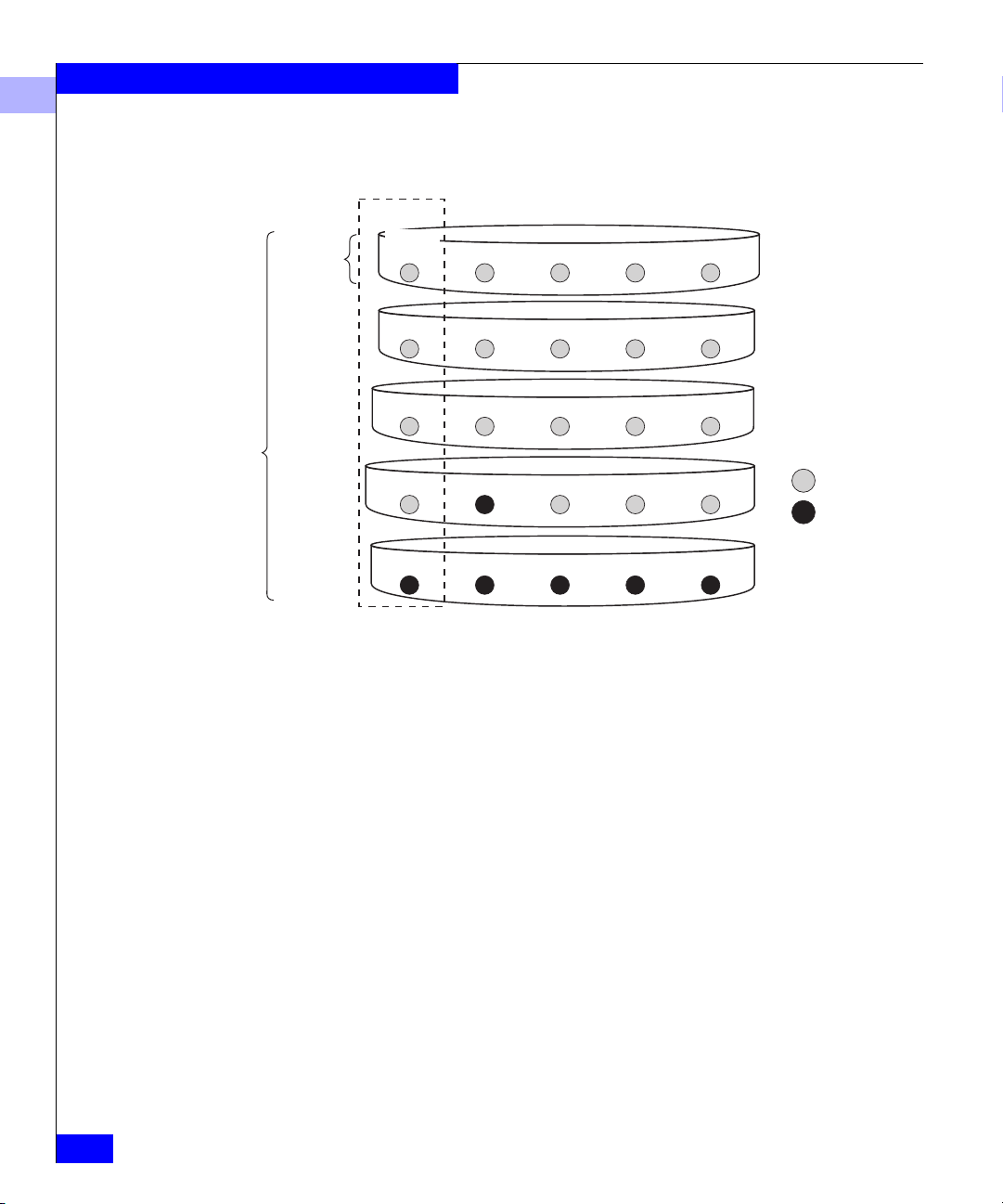
RAID 1/0 Group (Mirrored RAID 0 Group)
A RAID 1/0 Group consists of four, six, eight, ten, twelve, fourteen,
or sixteen disks. These disks make up two mirror images, with each
image including two to eight disks. The hardware automatically
mirrors the disks. A RAID 1/0 Group uses disk striping. It combines
the speed advantage of RAID 0 with the redundancy advantage of
mirroring. With a RAID 1/0 Group, you can create up to 32 RAID 1/0
LUNs to apportion disk space to different users, servers, and
applications.
The following figure shows the distribution of user data with the
default stripe element size of 128 sectors (65,536 bytes) in a six-disk
RAID 1/0 Group. Notice that the disk block addresses in the stripe
proceed sequentially from the first mirrored disks (first and fourth
disks) to the second mirrored disks (second and fifth disks), to the
third mirrored disks (third and sixth disks), and then from the first
mirrored disks, and so on.
2-8
EMC Fibre Channel Storage System Model FC4700 Configuration Planning Guide
Page 33

Stripe
size
Stripe
element
size
Stripe
Blocks
0-127 384-511
First disk of primary image
Second disk of primary image
512-639128-255 1664-17911280-1407896-1023
Third disk of primary image
256-383
640-767
1024-1151
1408-1535
1536-16631152-1279768-895
1792-1919
RAID Types and Tradeoffs
2
…
…
…
Figure 2-5 RAID 1/0 Group
Individual Disk Unit
First disk of secondary image
384-511
768-895
1152-1279
1536-16630-127
…
User data
Second disk of secondary image
128-255
512-639
896-1023
1280-1407
1664-1791
…
Third disk of secondary image
256-383
640-767
1024-1151
1408-1535
1792-1919
…
EMC1818
A RAID 1/0 Group can survive the failure of multiple disks,
providing that one disk in each image pair survives.
An individual disk unit is a disk bound to be independent of any
other disk in the cabinet. An individual unit has no inherent high
availability, but you can make it highly available by using software
mirroring with another individual unit. You can create one LUN per
individual disk unit. If you want to apportion the disk space, you can
do so using partitions, file systems, or user directories.
Hot Spare
A hot spare is a dedicated replacement disk on which users cannot
store information. A hot spare is global: if any disk in a RAID 5
Group, RAID 3 Group, RAID 1 mirrored pair, or RAID 1/0 Group
fails, the SP automatically rebuilds the failed disk’s structure on the
hot spare. When the SP finishes rebuilding, the disk group functions
RAID Types
2-9
Page 34

RAID Types and Tradeoffs
2
as usual, using the hot spare instead of the failed disk. When you
replace the failed disk, the SP copies the data from the former hot
spare onto the replacement disk.
When the copy is done, the disk group consists of disks in the original
slots, and the SP automatically frees the hot spare to serve as a hot
spare again. A hot spare is most useful when you need the highest
data availability. It eliminates the time and effort needed for someone
to notice that a disk has failed, find a suitable replacement disk, and
insert the disk.
When you plan to use a hot spare, make sure the disk has the capacity to
serve in any RAID Group in the storage-system chassis. A RAID Group
cannot use a hot spare that is smaller than a failed disk in the group.
You can have one or more hot spares per storage-system chassis. You
can make any disk in the chassis a hot spare, except for one of the
disks that stores Base Software or the write cache vault. That is, a hot
spare can be any of the following disks:
DPE system without write caching: disk IDs 003-199
DPE system with write caching: disk IDs 009-199
2-10
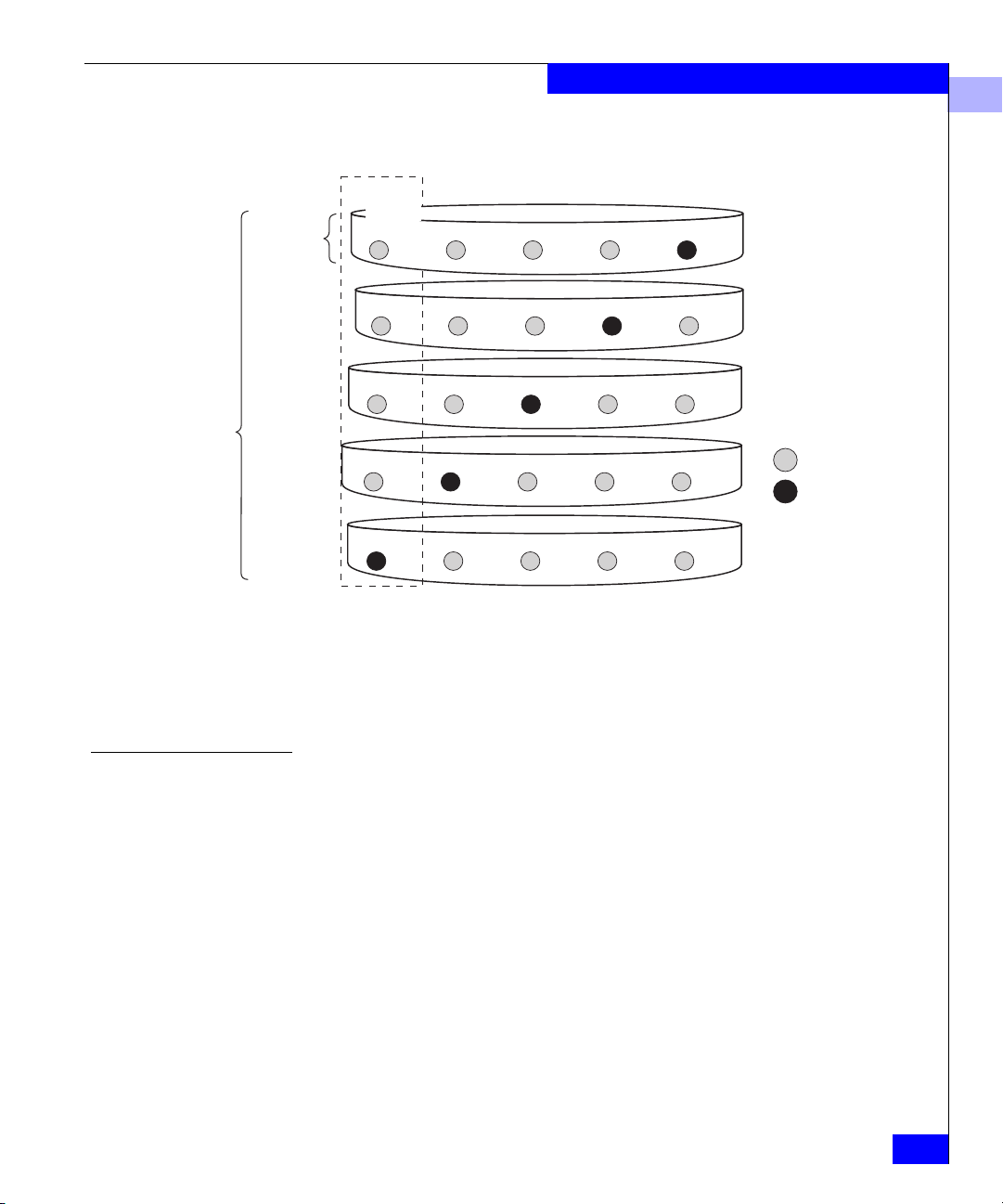
An example of hot spare usage for a deskside DPE storage system
follows.
EMC Fibre Channel Storage System Model FC4700 Configuration Planning Guide
Page 35

RAID Types and Tradeoffs
0 1 2 3 4 5 6 7 8
9
Hot
spare
1. RAID 5 Group consists of disk modules 0-4; RAID 1
mirrored pair is modules 5 and 6; hot spare is module 9.
2. Disk module 3 fails.
3. RAID 5 Group becomes modules 0, 1, 2, 9, and 4; now
no hot spare is available.
4. System operator replaces failed module 3 with a
functional module.
5. Once again, RAID 5 Group consists of modules 0-4 and
hot spare is 9.
EMC1819
2
Figure 2-6 How a Hot Spare Works
RAID Types
2-11
Page 36

RAID Types and Tradeoffs
2
RAID Benefits and Tradeoffs
This section reviews RAID types and explains their benefits and
tradeoffs. You can create seven types of LUN:
• RAID 5 Group (individual access array)
• RAID 3 Group (parallel access array)
• RAID 1 mirrored pair
• RAID 1/0 Group (mirrored RAID 0 Group); a RAID 0 Group
mirrored by the storage-system hardware
• RAID 0 Group (nonredundant individual access array); no
inherent high-availability features
• Individual unit; no inherent high-availability features
• Hot spare; serves only as an automatic replacement for any disk
in a RAID type other than 0; does not store data during normal
system operations
Plan the disk unit configurations carefully. After a disk has been bound into a
LUN, you cannot change the RAID type of that LUN without unbinding it,
and this means losing all data on it.
2-12
The following table compares the read and write performance,
tolerance for disk failure, and relative cost per megabyte (Mbyte) of
the RAID types. Figures shown are theoretical maximums.
EMC Fibre Channel Storage System Model FC4700 Configuration Planning Guide
Page 37

RAID Types and Tradeoffs
Table 2-1 Performance, Availability, and Cost of RAID Types (Individual Unit = 1.0)
2
Performance
Relative read
Disk configuration
RAID 5 Group with
fivedisks
RAID 3 Group with
fivedisks
RAID 1 mirrored pair Up to 2 Up to 1 2
RAID 1/0 Group with
10 disks
Individual unit 1 1 1
Notes: These performance numbers are not based on storage-system caching. With caching,
the performance numbers for RAID 5 writes improve significantly.
Performance multipliers vary with load on server and storage system.
performance
without cache
Up to 5 with five disks
(for small I/O requests, 2
to 8 Kbytes)
Up to 4 (for large I/O
requests)
Up to 10 Up to 5
Relative write
performance
without cache
Up to 1.25 with five disks
(for small I/O requests, 2 to
8 Kbytes)
Up to 4 (for large I/O
requests)
Relative
cost per
Mbyte
1.25
1.25
RAID 5, with individual access, provides high read throughput by a
allowing simultaneous reads from each disk in the group. RAID 5
write performance is excellent when the storage system uses write
caching.
RAID 3, with parallel access, provides high throughput for
sequential, large block-size requests (blocks of more than 64 Kbytes).
With RAID 3, the system accesses all five disks in each request but
need not read data and parity before writing – advantageous for large
requests but not for small ones. RAID 3 employs SP memory without
caching, which means you do not need the second SP and BBU that
caching requires.
Generally, the performance of a RAID 3 Group increases as the size of
the I/O request increases. Read performance increases rapidly with
read requests up to 1Mbyte. Write performance increases greatly for
sequential write requests that are greater than 256 Kbytes. For
applications issuing very large I/O requests, a RAID 3 LUN provides
significantly better write performance than a RAID 5 LUN.
We do not recommend using RAID 3 in the same storage-system
chassis with RAID 5 or RAID 1/0.
RAID Benefits and Tradeoffs
2-13
Page 38

RAID Types and Tradeoffs
2
A RAID 1 mirrored pair has its disks locked in synchronization, but
the SP can read data from the disk whose read/write heads are closer
to it. Therefore, RAID 1 read performance can be twice that of an
individual disk while write performance remains the same as that of
an individual disk.
A RAID 0 Group (nonredundant individual access array) or RAID
1/0 Group (mirrored RAID 0 Group) can have as many I/O
operations occurring simultaneously as there are disks in the group.
Since RAID 1/0 locks pairs of RAID 0 disks the same way as RAID 1
does, the performance of RAID 1/0 equals the number of disk pairs
times the RAID 1 performance number. If you want high throughput
for a specific LUN, use a RAID 1/0 or RAID 0 Group. A RAID 1/0
Group requires at least four disks; a RAID 0 Group, at least three
disks.
An individual unit needs only one I/O operation per read or write
operation.
RAID types 5, 1, 1/0, and 0 allow multiple LUNs per RAID Group. If
you create multiple LUNs on a RAID Group, the LUNs share the
RAID Group disks, and the I/O demands of each LUN affect the I/O
service time to the other LUNs. For best performance, you may want
to use one LUN per RAID Group.
Storage Flexibility
Certain RAID Group types — RAID 5, RAID 1, RAID 1/0, and RAID
0 — let you create up to 32 LUNs in each group. This adds flexibility,
particularly with large disks, since it lets you apportion LUNs of
various sizes to different servers, applications, and users. Conversely,
with RAID 3, there can be only one LUN per RAID Group, and the
group must include five or nine disks — a sizable block of storage to
devote to one server, application, or user. However, the nature of
RAID 3 makes it ideal for that single-threaded type of application.
Data Availability and Disk Space Usage
If data availability is critical and you cannot afford to wait hours to
replace a disk, rebind it, make it accessible to the operating system,
and load its information from backup, then use a redundant RAID
Group: RAID 5, RAID 3, RAID 1 mirrored pair, or RAID 1/0. If data
availability is not critical, or disk space usage is critical, bind an
individual unit.
2-14
EMC Fibre Channel Storage System Model FC4700 Configuration Planning Guide
Page 39

RAID Types and Tradeoffs
A RAID 1 mirrored pair or RAID 1/0 Group provides very high data
availability. They are more expensive than RAID 5 or RAID 3 Groups,
since only 50 percent of the total disk capacity is available for user
data, as shown on page 2-13.
A RAID 5 or RAID 3 Group provides high data availability, but
requires more disks than a mirrored pair. In a RAID 5 or RAID 3
Group of five disks, 80 percent of the disk space is available for user
data. So RAID 5 and RAID 3 Groups use disk space much more
efficiently than a mirrored pair. A RAID 5 or RAID 3 Group is usually
more suitable than a RAID 1 mirrored pair for applications where
high data availability, good performance, and efficient disk space
usage are all of relatively equal importance.
For a LUN in any RAID Group, to provide for disaster recovery, you
can establish a remote mirror at a distant site.
2
RAID Benefits and Tradeoffs
2-15
Page 40

RAID Types and Tradeoffs
2
RAID 5 Group RAID 3 Group
1st disk
user and parity data
2nd disk
user and parity data
3rd disk
user and parity data
4th disk
user and parity data
5th disk
user and parity data
Disk Mirror (RAID 1 mirrored pair)
1st disk
user data
2nd disk
user data
1st disk
user data
2nd disk
user data
3rd disk
user data
4th disk
user data
5th disk
parity data
50% user data
50% redundant dat
80% user data
20% parity dat
50% user data
50% redundant data
a
100% user dat
a
RAID 0 Group
(nonredundant array)
1st disk
user data
a
2nd disk
user data
3rd disk
user data
RAID 1/0 Group
1st disk
user data
2nd disk
user data
3rd disk
user data
4th disk
user data
5th disk
user data
2-16
Individual Disk Unit
User data
Figure 2-7 Disk Space Usage in the RAID Configuration
100% user dat
a
Hot Spare
Reserved
No user dat
a
A RAID 0 Group (nonredundant individual access array) provides all
its disk space for user files, but does not provide any high availability
features. For high availability, you can use a RAID 1/0 Group
instead.
A RAID 1/0 Group provides the best combination of performance
and availability, at the highest cost per Mbyte of disk space.
An individual unit, like a RAID 0 Group, provides no
high-availability features. All its disk space is available for user data,
as shown in the figure above.
EMC Fibre Channel Storage System Model FC4700 Configuration Planning Guide
6th disk
user data
EMC1820
Page 41

Guidelines for RAID Groups
To decide when to use a RAID 5 Group, RAID 3 Group, mirror (that
is, a RAID 1 mirrored pair or RAID 1/0 Group, a RAID 0 Group,
individual disk unit, or hot spare), you need to weigh these factors:
• Importance of data availability
• Importance of performance
• Amount of data stored
• Cost of disk space
The following guidelines will help you decide on RAID types.
Use a RAID 5 Group (individual access array) for applications
where
• Data availability is very important.
• Large volumes of data will be stored.
• Multitask applications use I/O transfers of different sizes.
• Excellent read and good write performance is needed (write
performance is very good with write caching).
RAID Types and Tradeoffs
2
• You want the flexibility of multiple LUNs per RAID Group.
Use a RAID 3 Group (parallel access array) for applications where
• Data availability is very important.
• Large volumes of data will be stored.
• A single-task application uses large I/O transfers (more than 64
Kbytes). The operating system must allow transfers aligned to
start at disk addresses that are multiples of 2 Kbytes from the start
of the LUN.
Use a RAID 1 mirrored pair for applications where
• Data availability is very important.
• Speed of write access is important and write activity is heavy.
Use a RAID 1/0 Group (mirrored nonredundant array) for
applications where
• Data availability is critically important.
• Overall performance is very important.
Guidelines for RAID Groups
2-17
Page 42

RAID Types and Tradeoffs
2
Use a RAID 0 Group (nonredundant individual access array) for
applications where
• High availability is not important.
• You can afford to lose access to all data stored on a LUN if a single
disk fails.
• Overall performance is very important.
Use an individual unit for applications where
• High availability is not important.
• Speed of write access is somewhat important.
Use a hot spare where
• In any RAID 5, RAID 3, RAID 1/0 or RAID 1 Group, high
availability is so important that you want to regain data
redundancy quickly without human intervention if any disk in
the group fails.
• Minimizing the degraded performance caused by disk failure in a
RAID 5 or RAID 3 Group is important.
2-18
EMC Fibre Channel Storage System Model FC4700 Configuration Planning Guide
Page 43

Sample Applications for RAID Types
This section describes some types of applications in which you would
want to use a RAID 5 Group, RAID 3 Group, RAID 1 mirrored pair,
RAID 0 Group (nonredundant array), RAID 1/0 Group, or individual
unit.
RAID 5 Group (individual access array) — Useful as a database
repository or a database server that uses a normal or low percentage
of write operations (writes are 33 percent or less of all I/O
operations). Use a RAID 5 Group where multitask applications
perform I/O transfers of different sizes. Write caching can
significantly enhance the write performance of a RAID 5 Group.
For example, a RAID 5 Group is suitable for multitasking
applications that require a large history database with a high read
rate, such as a database of legal cases, medical records, or census
information. A RAID 5 Group also works well with transaction
processing applications, such as an airline reservations system, where
users typically read the information about several available flights
before making a reservation, which requires a write operation. You
could also use a RAID 5 Group in a retail environment, such as a
supermarket, to hold the price information accessed by the
point-of-sale terminals. Even though the price information may be
updated daily, requiring many write operations, it is read many more
times during the day.
RAID Types and Tradeoffs
2
RAID 3 Group — A RAID 3 Group (parallel access array) works well
with a single-task application that uses large I/O transfers (more than
64 Kbytes), aligned to start at a disk address that is a multiple of 2
Kbytes from the beginning of the logical disk. RAID 3 Groups can use
SP memory to great advantage without the second SP and battery
backup unit required for storage-system caching.
You might use a RAID 3 Group for a single-task application that does
large I/O transfers, like a weather tracking system, geologic charting
application, medical imaging system, or video storage application.
RAID 1 mirrored pair — A RAID 1 mirrored pair is useful for
logging or record-keeping applications because it requires fewer
disks than a RAID 0 Group (nonredundant array) and provides high
availability and fast write access. Or you could use it to store daily
updates to a database that resides on a RAID 5 Group, and then,
during off-peak hours, copy the updates to the database on the
RAID 5 Group.
Sample Applications for RAID Types
2-19
Page 44

RAID Types and Tradeoffs
2
RAID 0 Group (nonredundant individual access array) — Use a
RAID 0 Group where the best overall performance is important. In
terms of high availability, a RAID 0 Group is less available than an
individual unit. A RAID 0 Group (like a RAID 5 Group) requires a
minimum of three disks. A RAID 0 Group is useful for applications
using short-term data to which you need quick access.
RAID 1/0 Group (mirrored RAID 0 Group) — A RAID 1/0 Group
provides the best balance of performance and availability. You can
use it very effectively for any of the RAID 5 applications. A RAID 1/0
Group requires a minimum of four disks.
Individual unit — An individual unit is useful for print spooling,
user file exchange areas, or other such applications, where high
availability is not important or where the information stored is easily
restorable from backup.
The performance of an individual unit is slightly less than a standard
disk not in an storage system. The slight degradation results from SP
overhead.
Hot spare — A hot spare provides no data storage but enhances the
availability of each RAID 5, RAID 3, RAID 1, and RAID 1/0 Group in
a storage system. Use a hot spare where you must regain high
availability quickly without human intervention if any disk in such a
RAID Group fails. A hot spare also minimizes the period of degraded
performance after a RAID 5 or RAID 3 disk fails.
2-20
What Next? This chapter explained RAID Group types and tradeoffs. To plan
LUNs and file systems, skip to Chapter 5. For details on the
storage-system hardware, skip to Chapter 6.
For storage-system management utilities, skip to Chapter 7.
EMC Fibre Channel Storage System Model FC4700 Configuration Planning Guide
Page 45

Invisible Body Tag
3
About MirrorView
Remote Mirroring
Software
This chapter introduces EMC MirrorView software — mirroring
software that works on FC4700 Fibre Channel disk-array storage
systems to create a byte-for-byte copy of one or more local LUNs
connected to a distant computer system.
Topics are
• What Is EMC MirrorView Software? ..............................................3-2
• MirrorView Features and Benefits...................................................3-4
• How MirrorView Handles Failures.................................................3-5
• MirrorView Example.........................................................................3-7
• MirrorView Planning Worksheet.....................................................3-9
About MirrorView Remote Mirroring Software
3-1
Page 46

About MirrorView Remote Mirroring Software
3
What Is EMC MirrorView Software?
EMC MirrorView is a software application that maintains a copy
image of a logical unit (LUN) at separate locations. The images are far
enough apart to provide for disaster recovery; that is, to let one image
continue if a serious accident or natural disaster disables the other.
The production image (the one mirrored) is called the primary image;
the copy image is called the secondary image. The primary image is
connected to a server called the production host. The secondary
image is maintained by a separate storage system that can be a
stand-alone storage system or connected to its own server. Both
storage systems are managed by the same management station,
which can promote the secondary image if the primary becomes
inaccessible.
3-2
EMC Fibre Channel Storage System Model FC4700 Configuration Planning Guide
Page 47

About MirrorView Remote Mirroring Software
The following figure shows two sites and a primary and secondary
image that includes one LUN. Notice that the storage-system SP As
and SP Bs are connected.
3
Highly available cluster
File Server
Operating
system A
Adapter
Adapter
Switch fabric
Cluster
Storage
Group
Database
Server
Storage
Group
Mail Server
Operating
system
SP A SP B
Adapter
Adapter
LUN
LUN
LUN
LUN
LUN
LUN
LUN
Database
Server 1
Operating
A
Switch fabric
system
B
Adapter
Adapter
Extended Distance Connections
Accounts Server
Storage Group
Database Server
Remote Mirror
Accounts
Server
Operating
system A
Adapter
Adapter
Switch fabric
SP A SP B
Switch fabric
LUN
LUN
LUN
LUN
LUN
LUN
LUN
Database
Server
Operating
system
B
Adapter
Adapter
2
Storage system 1 Storage system 2
Figure 3-1 Sites with MirrorView Primary and Secondary Images
The connections between storage systems require fibre channel cable
and GigaBit Interface Converters (GBICs) at each SP. If the
connections include extender boxes, then the distance between
storage systems can be up to the maximum supported by the
extender — generally 40-60 kilometers.
Without extender boxes, the maximum distance is 500 meters.
What Is EMC MirrorView Software?
EMC2000
3-3
Page 48

About MirrorView Remote Mirroring Software
3
MirrorView Features and Benefits
MirrorView mirroring adds value to customer systems by offering
the following features:
• Provision for disaster recovery with minimal overhead
• Local high availability
• Cross mirroring
• Integration with EMC SnapView LUN snapshot copy software
Provision for Disaster Recovery with Minimal Overhead
Provision for disaster recovery is the major benefit of MirrorView
mirroring. Destruction of the primary data site would cripple or ruin
many organizations. MirrorView lets data processing operations
resume within a working day.
MirrorView is transparent to servers and their applications. Server
applications do not know that a LUN is mirrored, and the effect on
performance is minimal.
MirrorView uses synchronous writes, which means that server writes
are acknowledged only after all secondary storage systems commit
the data. This type of mirroring is in use by most disaster recovery
systems sold today.
Local High Availability
Cross Mirroring
3-4
EMC Fibre Channel Storage System Model FC4700 Configuration Planning Guide
MirrorView is not server-based, therefore it uses no server I/O or
CPU resources. The mirror processing is performed on the storage
system.
MirrorView operates in a highly available environment. There are
two host bus adapters (HBAs) per host, and there are two SPs per
storage system. If a single adapter or SP fails, the path in the
surviving SP can take control of (trespass) any LUNs owned by the
failed adapter or SP. The high availability features of RAID protect
against disk failure. Mirrors are resilient to an SP failure in the
primary or secondary storage system.
The primary or secondary role applies to just one remote mirror. A
storage system can maintain a primary image with one mirror and a
secondary image with another mirror. This allows the use of server
Page 49

resources at both sites while maintaining duplicate copies of all data
at both sites.
Integration with EMC SnapView LUN Copy Software
EMC SnapView software allows users to create a snapshot copy of an
active LUN at any point in time. The snapshot copy is a consistent
image that can serve for backup while I/O continues to the original
LUN. You can use SnapView in conjunction with MirrorView to make
a backup copy at a remote site.
A common situation for disaster recovery is to have a primary and a
secondary site that are geographically separate. MirrorView ensures
that the data from the primary site replicates to the secondary site.
The secondary site sits idle until there is a failure of the primary site.
With the addition of SnapView at the secondary site, the secondary
site can take snapshot copies of the replicated images and back them
up to other media, providing time-of-day snapshots of data on the
production host with minimal overhead.
About MirrorView Remote Mirroring Software
3
How MirrorView Handles Failures
When a failure occurs during normal operations, MirrorView
implements several actions to recover.
Primary Image Failure
When the server or storage system running the primary image fails,
access to the mirror stops until a secondary is promoted to primary or
until the primary is repaired. If promotion occurred, then the primary
was demoted to secondary and it must be synchronized before
rejoining the mirror. If the primary was repaired, then the mirror
continues as before the failure.
For fast synchronization of the images after a primary failure,
MirrorView provides a write-intent log feature. The write intent log
records the current activity so that a repaired primary need only copy
over data that recently changed (instead of the entire image), thus
greatly reducing the recovery time.
How MirrorView Handles Failures
3-5
Page 50

About MirrorView Remote Mirroring Software
3
Secondary Image Failure
A secondary image failure may bring the mirror below the minimum
number of images required; if so, this triggers a mirror failure. When
a primary cannot communicate with a secondary image, it marks the
secondary as unreachable and stops trying to write to it. However, the
secondary image remains a member of the mirror.
The primary also attempts to minimize the amount of work required
to synchronize the secondary after it recovers. It does this by
fracturing the mirror. This means that, while the secondary is
unreachable, the primary keeps track of all write requests so that only
those blocks that were modified need to be copied to the secondary
during recovery. When the secondary is repaired, the software writes
the modified blocks to it, and then starts mirrored writes to it.
The following table shows how MirrorView might help you recover
from system failure at the primary and secondary sites. It assumes
that the mirror is active and is in the in-sync or consistent state.
Table 3-1 MirrorView Recovery Scenarios
Event Result and recovery
Server or storage system
running primary image fails.
Storage system running
secondary image fails.
3-6
EMC Fibre Channel Storage System Model FC4700 Configuration Planning Guide
Option 1 - Catastrophic failure, repair is difficult or impossible.
The mirror goes to the attention state. If a host is attached to the secondary storage system,
the administrator promotes secondary image, and then takes other prearranged recovery
steps required for application startup on standby host.
Note: Any writes in progress when the primary image fails may not propagate to the secondary
image. Also, if the remote image was fractured at the time of the failure, any writes since the
fracture will not have propagated.
Option 2 -Non-catastrophic failure, repair is feasible.
The mirror goes to the attention state. The administrator has the problem fixed, and then
synchronizes the secondary image. The write intent log, if used, shortens the sync time
needed. If a write intent log is not used, or the secondary LUN was fractured at the time of
failure, then a full synchronization is necessary.
The mirror goes to attention state, rejecting I/O. The administrator has a choice: If the
secondary can easily be fixed (for example, if someone pulled out a cable), then the
administrator can have it fixed and let things resume. If the secondary can't easily be fixed, the
administrator can reduce the minimum number of secondary images required to let the mirror
become active. Later, the secondary can be fixed and the minimum number of required images
can be changed.
Page 51

MirrorView Example
A
D
Highly available cluster
File Server
Operating
system A
Adapter
Adapter
Mail Server
Operating
system
A
Adapter
Adapter
Database
Server 1
Operating
system
Adapter
Adapter
About MirrorView Remote Mirroring Software
3
ccounts
Server
Operating
B
system A
Adapter
Adapter
atabase
Server
Operating
system
Adapter
Adapter
B
2
Switch fabric
Cluster
Storage
Group
Database
Server
Storage
Group
Switch fabric
Extended Distance Connections
SP A SP B
LUN
LUN
LUN
LUN
LUN
LUN
LUN
Storage system 1
Figure 3-2 Sample MirrorView Configuration
Accounts Server
Storage Group
Database Server
Remote Mirror
In the figure above, Database Server 1, the production host, executes
customer applications. These applications access data on
Storage system 1, in the database server Storage Group.
Storage system 2 is 40 km away and mirrors the data on the database
server Storage Group. The mirroring is synchronous, so that
Storage system 2 always contains all data modifications that are
acknowledged by Storage system 1 to the production host.
Switch fabric
SP A SP B
Storage system
Switch fabric
LUN
LUN
LUN
LUN
LUN
LUN
LUN
2
EMC2000
Each server has two paths — one through each SP — to each storage
system. If a failure occurs in a path, then the storage-system software
MirrorView Example
3-7
Page 52

About MirrorView Remote Mirroring Software
3
may switch to the path through the other SP (transparent to any
applications).
The server sends a write request to an SP in Storage-system 1, which
then writes data to its LUN. Next, the data is sent to the
corresponding SP in Storage-system 2, where it is stored on its LUN
before the write is acknowledged to the production host.
Database server 2, the standby host, has no direct access to the
mirrored data. (There need not be a server at all at the standby site; if
there is none, the LAN connects to the SPs as shown.) This server
runs applications that access other data stored on Storage system 2. If
a failure occurs in either the production host or Storage system 1, an
administrator can use the management station to promote the image
on Storage-system 2 to the primary image. Then the appropriate
applications can start on any connected server (here,
Database server 2) with full access to the data. The mirror will be
accessible in minutes, although the time needed for applications to
recover will vary.
3-8
EMC Fibre Channel Storage System Model FC4700 Configuration Planning Guide
Page 53

MirrorView Planning Worksheet
To plan, you must decide whether you want to use a write intent log
and, if so, the LUNs you will bind for this. You will also need to
complete a MirrorView mirroring worksheet.
Note that you must assign each primary image LUN to a Storage
Group (as with any normal LUN), but must not assign a secondary
image LUN to a Storage Group.
MirrorView Mirroring Worksheet
About MirrorView Remote Mirroring Software
3
Production
host name
Use Write Intent
Log - Y/N (about
256 Mbytes per
storage system) SP(A/B)
Remote
mirror
name
Secondary
image contact
person
Primary LUN ID, size,
and file system name
Storage
Group
Number/Name
What Next? This chapter explained the MirrorView remote mirroring software.
For information on SnapView snapshot copy software, continue to
the next chapter. To plan LUNs and file systems, skip to Chapter 5.
For details on the storage-system hardware, skip to Chapter 6. For
storage-system management utilities, skip to Chapter 7.
Secondary
image LUN ID
MirrorView Planning Worksheet
3-9
Page 54

About MirrorView Remote Mirroring Software
3
3-10
EMC Fibre Channel Storage System Model FC4700 Configuration Planning Guide
Page 55

nvisible Body Tag
4
About SnapView
Snapshot Copy
Software
This chapter introduces EMC SnapView software that creates LUN
snapshots to be used for independent data analysis or backup with
EMC FC 4700 Fibre Channel disk-array storage systems.
Major sections are
• What Is EMC SnapView Software? .................................................4-2
• Sample Snapshot Session..................................................................4-4
• Snapshot Planning Worksheet .........................................................4-5
About SnapView Snapshot Copy Software
4-1
Page 56

About SnapView Snapshot Copy Software
4
What Is EMC SnapView Software?
EMC SnapView is a software application that captures a snapshot
image of a LUN and retains the image independently of subsequent
changes to the LUN. The snapshot image can serve as a base for
decision support, revision testing, backup, or in any situation where
you need a consistent, copyable image of real data.
SnapView can create or destroy a snapshot in seconds, regardless of
the LUN size, since it does not actually copy data. The snapshot
image consists of the unchanged LUN blocks and, for each block that
changes from the snapshot moment, a copy of the original block. The
software stores the copies of original blocks in a private LUN called
the snapshot cache. For any block, the copy happens only once, when
the block is first modified. In summary:
snapshot copy = unchanged-blocks-on-source-LUN + blocks-cached
As time passes, and I/O modifies the source LUN, the number of
blocks stored in the snapshot cache grows. However, the snapshot
copy, composed of all the unchanged blocks — some from the source
LUN and some from the snapshot cache — remains unchanged.
4-2
The snapshot copy does not reside on disk modules like a
conventional LUN. However, the snapshot copy appears as a
conventional LUN to another host. Any other server can access the
copy for data processing analysis, testing, or backup.
The following figure shows how a snapshot session works: the
production host with the source LUN, the snapshot cache, and
second host with access to the snapshot copy.
EMC Fibre Channel Storage System Model FC4700 Configuration Planning Guide
Page 57

About SnapView Snapshot Copy Software
4
Production
host
Continuous
I/O
Storage system
Source
LUN
Snapshot
Figure 4-1 SnapView Operations Model
Snapshot
cache
Second
host
SnapView offers several important benefits:
• It allows full access to production data with minimal impact on
performance;
• For decision support or revision testing, it provides a coherent,
readable and writable copy of real production data at any given
point in time; and
• For backup, it practically eliminates the time that production data
spends offline or in hot backup mode. And it off-loads the backup
overhead from the production host to another host.
The snapshot is a composite
of source LUN and cache
data that is accessible as
long as the session lasts.
EMC1822
Snapshot Components
A snapshot session uses three components: a production host, a
second host, and a snapshot copy session.
• The production host runs the customer applications on the LUN
that you want to copy, and allows the management software to
create, start, and stop snapshot sessions.
• The second host reads the snapshot during the snapshot session,
and performs analysis or backup using the snapshot.
• A snapshot session makes the snapshot copy accessible to the
second host; it starts and stops according to directives you give
using Navisphere software on the production host.
What Is EMC SnapView Software?
4-3
Page 58

About SnapView Snapshot Copy Software
4
Sample Snapshot Session
The following figure shows how a sample snapshot session starts,
runs, and stops.
1. Before session starts
Production
Host
Source
LUN
Second
Host
SnapshotSnapshot
cache
4. At end of operation (4:15 p.m.)
Production
Host
Source
LUN
Key:
Unchanged chunks
on source LUN
Changed chunks
on source LUN
Unchanged chunks in
cache and snapshot
2. At session start (2:00 p.m.)
Production
Host
Source
LUN
Second
Host
Cache
Second
Host
SnapshotCache
Snapshot
(pointers to
chunks)
3. At start of operation (2:02 p.m.)
Production
host
Source
LUN
Second
host
Cache
5. At session end (4:25 p.m.)
Production
Host
Source
LUN
Second
Host
SnapshotCache
Snapshot
(pointers to
chunks)
EMC1823
4-4
Figure 4-2 How a Snapshot Session Starts, Runs, and Stops
EMC Fibre Channel Storage System Model FC4700 Configuration Planning Guide
Page 59

About SnapView Snapshot Copy Software
Snapshot Planning Worksheet
The following information is needed for system setup to let you bind
one or more LUNs for the snapshot cache.
Snapshot Cache Setup Information (For Binding)
4
Snapshot
source LUN
SP
size
A
B
For each session, you must complete a snapshot session worksheet.
Note that you must assign the LUN and snapshot to different Storage
Groups. One Storage Group should include the production host and
source LUN; another Storage Group should include the second host
and the snapshot.
Snapshot Session Worksheet
LUN Snapshot cache
Production
host
name
Storage
Group
ID
Size
(Mb)
RAID type for
snapshot
cache
Application, file
system, or
database name LUN ID
RAID Group ID
of parent RAID
Group
Size
(Mb)
LUN size (Mbytes,
we suggest 20% of
source LUN size)
SP
Chunk
(cache
write)
size
(both
LUN
and
cache)
Cache LUN ID
(complete
after binding)
Time
of day
to
copy
Session
nameLUN ID
Snapshot Planning Worksheet
4-5
Page 60

About SnapView Snapshot Copy Software
4
What Next? This chapter explained the SnapView snapshot copy software. To
plan LUNs and file systems, continue to the next chapter. For details
on the storage-system hardware, skip to Chapter 6. For
storage-system management utilities, skip to Chapter 7.
4-6
EMC Fibre Channel Storage System Model FC4700 Configuration Planning Guide
Page 61

Invisible Body Tag
5
Planning File Systems
and LUNs
This chapter shows a sample RAID, LUN, and Storage Group
installation with sample shared switched and unshared direct
storage, and then provides worksheets for planning your own
storage installation. Topics are
• Multiple Paths to LUNs ....................................................................5-2
• Sample Shared Switched Installation..............................................5-3
• Sample Unshared Direct Installation..............................................5-7
• Planning Applications, LUNs, and Storage Groups.....................5-8
Planning File Systems and LUNs
5-1
Page 62

Planning File Systems and LUNs
5
Multiple Paths to LUNs
A shared storage system includes one or more servers, two Fibre
Channel switches, one or more storage systems, each with two SPs
and the Access Logix option.
With shared storage (switched or direct), there are at least two paths
to each LUN in the storage system. The storage-system Base Software
detects both paths and, using optional Application Transparent
Failover (ATF) software, can automatically switch to the other path,
without disrupting applications, if a device (such as a host-bus
adapter or cable) fails.
With unshared storage (one server direct connection), if the server
has two adapters and the storage system has two SPs, ATF performs
the same function as with shared systems: automatically switches to
the other path if a device (such as host bus adapter or cable) fails.
And with two adapters and two SPs (switched or unshared), ATF can
send I/O to each available paths in round-robin sequence (multipath
I/O) for dynamic load sharing and greater throughput.
5-2
EMC Fibre Channel Storage System Model FC4700 Configuration Planning Guide
Page 63

Sample Shared Switched Installation
The following figure shows a sample shared storage system
connected to three servers: two servers in a cluster and one server
running a database management program.
Disk IDs have the form b e d, where b is the FC4700 back-end bus
number (0, which can be omitted, or 1), e is the enclosure number, set
on the enclosure front panel (always 0 for the DPE), and d is the disk
position in the enclosure (left is 0, right is 9).
Planning File Systems and LUNs
5
Sample Shared Switched Installation
5-3
Page 64

Planning File Systems and LUNs
5
Highly available cluster
Database Server (DS)
Operating
system B
Adapter
Adapter
Switch fabric Switch fabric
Spare
Private
Spare
storage
Cluster
Storage
Group
MS R5
ISP A mail
File Server (FS)
Operating
system A
Adapter
Adapter
SP A
Unbound
disks
FS R5
Apps
FS R5
Files A
MS R5
ISP B mail
MS R5
Users
SP B
FS R5
Users
FS R5
Files B
MS R5
Specs
Mail Server (MS)
Operating
system
B
Adapter
Adapter
Disk ID
s
030-039
120-129
020-029
110-119
010-019
5-4
Database
DS R5
Users
DS R5
Dbase2
100-109
Server
Storage
Group
Figure 5-1 Sample Shared Switched Storage Configuration
EMC Fibre Channel Storage System Model FC4700 Configuration Planning Guide
DS R1
Log D1
DS R1
Log D2
DS R5
(6 disks)
Dbase1
000-009
Path
Path 2
1
EMC1824
Page 65

Planning File Systems and LUNs
The storage-system disk IDs and Storage Group LUNs are as follows.
5
Database Server LUNs (DS) - SP A
File Server LUNs (FS) - SP B Mail Server LUNs (MS) - SP A
RAID type, storage type
Disk IDs
000,001 RAID 1, Log file for
database Dbase1
002, 003 RAID 1, Log file for
database Dbase2
004-009 RAID 5 (6 disks), Dbase1
100-104 RAID 5, Users
105-109 RAID 5, Dbase2
020, 021 – Hot spare (automatically replaces a failed disk in any server’s LUN)
RAID type, storage type
Disk IDs
010-014 RAID 5, Applications
015-019 RAID 5, Users
110-114 RAID 5, ISP A mail
115-119 RAID 5, ISP B mail
Clustered System LUNs
Disk IDs
020-024 RAID 5, Files A
025-029 RAID 5, Files B
120-124 RAID 5, Users
125-129 RAID 5, Specs
With 36-Mbyte disks, the LUN storage capacities and drive names are
as follows.
Database Server — 540 Gbytes on four LUNs
DS R5
Users
DS R5
Dbase2
Unit users on five disks bound as a RAID 5 Group for
144 Gbytes of storage; for user directories.
Unit dbase2 on five disks bound as a RAID 5 Group
for 144 Gbytes of storage; for the second database
system.
DS R1
Log 1
Unit logfDbase1 on two disks bound as a RAID 1
mirrored pair for 36 Gbytes of storage; for database 1
log files.
RAID type, storage type
DS R1
Log 2
DS R5
Dbase1
Unit logfDbase2 on two disks bound as a RAID 1
mirrored pair for 36 Gbytes of storage; for database 2
log files.
Unit dbase on six disks bound as a RAID 5 Group for
180 Gbytes of storage; for the database 1 system.
Sample Shared Switched Installation
5-5
Page 66

Planning File Systems and LUNs
5
File Server — 576 Gbytes on four LUNs.
FS R5
Apps
FS R5
Users
FS R5
FilesA
FS R5
FilesB
Unit S on five disks bound as a RAID 5 Group for
144 Gbytes of storage; for applications.
Unit T on five disks bound as a RAID 5 Group for
144 Gbytes of storage; for user directories and files.
Unit U on five disks bound as a RAID 5 Group for
144 Gbytes of storage; for file storage.
Unit V on five disks bound as a RAID 5 Group for
144 Gbytes of storage; for file storage.
Mail Server — 576 Gbytes on four LUNs
MS R5
Users
MS R5
Specs
MS R5
ISP mail
Unit Q on five disks bound as a RAID 5 Group for
144 Gbytes of storage; for user directories and files.
Unit R on five disks bound as a RAID 5 Group for
144 Gbytes of storage; for specifications.
Unit O on five disks bound as a RAID 5 Group for
144 Gbytes of storage; for the mail delivered via ISPA.
5-6
MS R5
ISP mail
EMC Fibre Channel Storage System Model FC4700 Configuration Planning Guide
Unit P on five disks bound as a RAID 5 Group for
144 Gbytes of storage; for the mail delivered via ISP B.
Page 67

Sample Unshared Direct Installation
This section shows the disks and LUNs in an unshared direct
storage-system installation.
To repeat from the previous section: disk IDs have the form b e d,
where b is the FC4700 back-end bus number (0, which can be omitted,
or 1), e is the enclosure number, set on the enclosure front panel
(always 0 for the DPE), and d is the disk position in the enclosure (left
is 0, right is 9).
Server
Adapter
Planning File Systems and LUNs
5
Adapter
Disk IDs
100-109
010-019
Figure 5-2 Unshared Direct Storage Example
SP A SP B
Database
RAID 5
Sys
RAID 1
Clients, mail
RAID 5
Users
RAID 5
If each disk holds 36 Gbytes, then the storage system provides the
server with 576 Gbytes of disk storage, all highly available; it
provides Server 2 with 180 Gbytes of storage, all highly available. The
storage-system disk IDs and LUNs are as follows.
LUNs - SP A and SP B, 576 Gbytes
RAID type, storage type, capacity
Disk IDs
000, 001 RAID 1, System disk, 36 Gbytes
002-009 RAID 5 (8 disks), Clients and Mail, 252 Gbytes
100-104 RAID 5, Database, 144Gbytes
105-109 RAID 5, Users, 144 Gbytes
Path
Path 2
1
EMC1825
Sample Unshared Direct Installation
5-7
Page 68

Planning File Systems and LUNs
5
Planning Applications, LUNs, and Storage Groups
This section helps you plan your storage use — the applications to
run, the LUNs that will hold them, and, for shared storage, the
Storage Groups that will belong to each server. The worksheets to
help you do this include
• Application and LUN planning worksheet — lets you outline
your storage needs.
• LUN and Storage Group planning worksheet — lets you decide
on the disks to compose the LUNs and the LUNs to compose the
Storage Groups for each server.
Unshared storage systems do not use Storage Groups. For unshared
storage, on the LUN and Storage Group worksheet, skip the Storage
Group entry.
• LUN details worksheet — lets you plan each LUN in detail.
Make as many copies of each blank worksheet as you need. You will
need this information later when you configure the storage system(s).
Application and LUN Planning
5-8
EMC Fibre Channel Storage System Model FC4700 Configuration Planning Guide
Sample worksheets appear later in this chapter.
Use the following worksheet to list the applications you will run, and
the RAID type and size of LUN to hold them. For each application
that will run, write the application name, file system (if any), RAID
type, LUN ID (ascending integers, starting with 0), disk space
required, and finally the name of the servers and operating systems
that will use the LUN.
Page 69

Application and LUN Planning Worksheet
Planning File Systems and LUNs
5
Application
File system,
partition, or drive
RAID type of
LUN
A sample worksheet begins as follows:
Application
Users RAID 5 0
Dbase2 RAID 5 0
Log file for
Dbase1
Log file for
Dbase2
Dbase1 RAI
File system,
partition, or drive
RAID type of
LUN
RAID 1 0
RAID 1 1
D 1/0 2
LUN
ID (hex)
LUN
ID (hex)
Disk space
required
(Gbytes)
Disk space
required
(Gbytes)
72 G
B
72 G
B
18 G
B
18 G
B
90 G
B
Server hostname and
operating system
Server hostname and
operating system
Ser
ver
1,UNIX
Ser
ver
1,UNIX
Ser
ver
1,UNIX
Ser
ver
1,UNIX
Ser
ver
2,UNIX
Completing the Application and LUN Planning Worksheet
Application. Enter the application name or type.
File system, partition, or drive. Write the drive letter (for Windows
only) and the partition, file system, logical volume, or drive letter
name, if any.
With a Windows operating system, the LUNs are identified by drive
letter only. The letter does not help you identify the disk
configuration (such as RAID 5). We suggest that later, when you use
Planning Applications, LUNs, and Storage Groups
5-9
Page 70

Planning File Systems and LUNs
5
the operating system to create a partition on a LUN, you use the disk
administrator software to assign a volume label that describes the
RAID configuration. For example, for drive T, assign the volume ID
RAID5_T. The volume label will then identify the drive letter.
RAID type of LUN. This is the RAID Group type you want for this
partition, file system, or logical volume. The features of RAID types
are explained in Chapter 3. For a RAID 5, RAID 1, RAID 1/0, and
RAID 0 Group, you can create one or more LUNs on the RAID
Group. For other RAID types, you can create only one LUN per RAID
Group.
LUN ID. The LUN ID is a hexadecimal number assigned when you
bind the disks into a LUN. By default, the ID of the first LUN bound
is 0, the second 1, and so on. Each LUN ID must be unique within the
storage system, regardless of its Storage Group or RAID Group.
The maximum number of LUNs supported on one host-bus adapter
depends on the operating system.
Disk space required (Gbytes). Consider the largest amount of disk
space this application will need, and then add a factor for growth.
Server hostname and operating system. Enter the server hostname
(or, if you don’t know the name, a short description that identifies the
server) and the operating system name, if you know it.
LUN and Storage Group Planning Worksheet
Use the following worksheet to select the disks that will make up the
LUNs and Storage Groups in each storage system. A storage system
is any group of enclosures connected to a DPE; it can include up to
nine DAE enclosures for a total of 100 disks. A storage system can
include up to 100 disks.
Unshared storage systems do not use Storage Groups. For unshared
storage, skip the Storage Group entry.
5-10
EMC Fibre Channel Storage System Model FC4700 Configuration Planning Guide
Page 71

y
Bus 0
s
enclosures
LUN and Storage Group Planning Worksheet
0 4 4
DAE
1 3 4
DAE
0 3 4
DAE
1 2 4
DAE
0 2 4
DAE
1 1 4
DAE
0 1 4
DAE
1 0 4
0 4 5
1 3 5
0 3 5
1
2 5
0 2 5
1 1 5
0 1 5
1 0 5
0 4 6
1 3 6
0 3 6
1 2 6
0 2 6
1 1 6
0 1 6
1 0 6
0 4 7
1 3 7
0 3 7
1 2 7
0 2 7
1 1 7
0 1 7
1 0 7
0 4 8
1 3 8
0 3 8
1 2 8
0 2 8
1 1 8
0 1 8
1 0 8
0 4 9
1 3 9
0 3 9
1 2 9
0 2 9
1 1 9
0 1 9
1 0 9
0 4 0
1 3 0
0 3 0
1 2 0
0 2 0
1 1 0
0 1 0
1 0 0
0 4 1
1 3 1
0 3 1
1 2 1
0 2 1
1 1 1
0 1 1
1 0 1
0 4 2
1 3 2
0 3 2
1 2 2
0 2 2
1 1 2
0 1 2
1 0 2
0 4 3
1 3 3
0 3 3
1 2 3
0 2 3
1 1 3
0 1 3
1 0 3
Planning File Systems and LUNs
5
Bus 1
enclosure
DAE
0 0 4
0 0 0
0 0 1
0 0 2
0 0 3
0 0 5
0 0 6
DPE
Storage-system number or name:_______________
Storage Group ID or name:______ Server hostname:_________________ Dedicated Shared
LUN ID or name_______RAID type ___ Cap. (Gb) _____ Disk IDs_____________________________________
LUN ID or name_______RAID type ___ Cap. (Gb) _____ Disk IDs_____________________________________
LUN ID or name_______RAID type ___ Cap. (Gb) _____ Disk IDs_____________________________________
LUN ID or name_______RAID type ___ Cap. (Gb) _____ Disk IDs_____________________________________
Storage Group ID or name:______ Server hostname:_________________ Dedicated Shared
LUN ID or name_______RAID type ___ Cap. (Gb) _____ Disk IDs_____________________________________
LUN ID or name_______RAID type ___ Cap. (Gb) _____ Disk IDs_____________________________________
LUN ID or name_______RAID type ___ Cap. (Gb) _____ Disk IDs_____________________________________
LUN ID or name_______RAID t
pe ___ Cap. (Gb) _____ Disk IDs_____________________________________
0 0 7
0 0 8
0 0 9
Navisphere Manager
displays disk IDs as
n-n-n
CLI recognizes disk IDs
as
n_n_n
Planning Applications, LUNs, and Storage Groups
5-11
Page 72

Planning File Systems and LUNs
5
Part of a sample LUN and Storage Group worksheet follows.
1 0 4
1 0 5
1 0 3
1 0 1
LUN 3
RAID 5
LUN 0
RAID 1
1 0 0
0 0 0
1 0 2
0 0 1
0 0 2
LUN 1
RAID 1
0 0 3
DAE
0 0 4
DPE
0 0 5
1 0 6
0 0 6
1 0 7
0 0 7
1 0 8
0 0 8
1 0 9
0 0 9
LUN 4
RAID 5
LUN 2
RAID 5
Storage-system number or name:_______________
Storage Group ID or name:______ Server hostname:_____________________ Dedicated Shared
LUN ID or name_______RAID type ___ Cap. (Gb) _____ Disk IDs_________________________________________
LUN ID or name_______RAID type ___ Cap. (Gb) _____ Disk IDs_________________________________________
LUN ID or name_______RAID type ___ Cap. (Gb) _____ Disk IDs_________________________________________
LUN ID or name_______RAID type ___ Cap. (Gb) _____ Disk IDs_________________________________________
0
1
2
3
0
4
SS1
Server1
1
1
5
5
0
5
18
18
90
72
Server1
72
000, 001
002, 003
004,005,006,007,008,009
100,101,102,103,104,105
106,107, 108, 109, 110
Completing the LUN and Storage Group Planning Worksheet
As shown, draw circles around the disks that will compose each
LUN, and within each circle specify the RAID type (for example,
RAID 5) and LUN ID. This is information you will use to bind the
disks into LUNs. For disk IDs, use the form shown. This form is
enclosure_diskID, where enclosure is the enclosure number (the bottom
one is 0, above it 1, and so on) and diskID is the disk position (left is 0,
next is 1, and so on).
X
X
5-12
None of the disks 000 through 008 may be used as a hot spare.
Next, complete as many of the Storage System sections as needed for
all the Storage Groups in the SAN (or as needed for all the LUNs with
unshared storage). Copy the (blank) worksheet as needed.
EMC Fibre Channel Storage System Model FC4700 Configuration Planning Guide
Page 73

LUN Details Worksheet
Planning File Systems and LUNs
5
For shared storage, if a Storage Group will be dedicated (not
accessible by another server in a cluster), mark the Dedicated box at
the end of its line; if the Storage Group will be accessible to one or
more other servers in a cluster, write the hostnames of all servers and
mark the Shared box.
For unshared storage, ignore the Dedicated/Shared boxes.
Use the LUN details worksheet to plan the individual LUNs. Blank
and sample completed LUN worksheets follow.
Complete as many blank worksheets as needed for all LUNs in
storage systems. For unshared storage, skip the Storage Group
entries.
Planning Applications, LUNs, and Storage Groups
5-13
Page 74

Planning File Systems and LUNs
5
LUN Details Worksheet
Storage system (complete this section once for each storage system)
Storage-system number or name:______
Storage-system installation type
❏ Unshared Direct o Shared-or-Clustered Direct ❏ Shared Switched
SP information: SP A: IP address or hostname:_______Port ALPA ID:_____ Memory(Mbytes):_____
SP B: IP address or hostname:_______Port ALPA ID:_____ Memory(Mbytes):_____
❏Caching Read cache size:__ MBWrite cache size: __ MB Cache page size (Kbytes):___
❏ RAID-3
LUN ID:_____ SP owner:
RAID Group ID: Size,GB: LUN size, GB: Disk IDs:
RAID type: ❏RAID 5 ❏RAID 3 - Memory, MB:___ ❏RAID 1 mirrored pair ❏RAID 0
❏RAID 1/0 ❏Individual disk ❏Hot spare
Caching: ❏Read and write ❏Write ❏Read ❏None
❏A ❏B SP bus (0 or 1):___
Servers that can access this LUN’s Storage Group:
Operating system information: Device name: File system, partition, or drive:
LUN ID:_____ SP owner: ❏A ❏B SP bus (0 or 1):___
RAID Group ID: Size,GB: LUN size,GB: Disk IDs:
RAID type: ❏RAID 5 ❏RAID 3 - Memory, MB:___ ❏ RAID 1 mirrored pair ❏ RAID 0
❏RAID 1/0 ❏Individual disk ❏Hot spare
Caching: ❏Read and write ❏Write ❏Read ❏None
Servers that can access this LUN’s Storage Group:
Operating system information: Device name: File system, partition, or drive:
LUN ID:_____ SP owner: ❏A ❏B SP bus (0 or 1):__ _
RAID Group ID: Size,GB: LUN size, GB: Disk IDs:
RAID type: ❏RAID 5 ❏RAID 3 - Memory, MB:___ ❏RAID 1 mirrored pair ❏ RAID 0
❏RAID 1/0 ❏Individual disk ❏Hot spare
Caching: ❏Read and write ❏Write ❏Read ❏None
Servers that can access this LUN’s Storage Group:
Operating system information: Device name: File system, partition, or drive:
5-14
EMC Fibre Channel Storage System Model FC4700 Configuration Planning Guide
Page 75

Planning File Systems and LUNs
LUN Details Worksheet
Storage system (complete this section once for each storage system)
Storage-system number or name:__SS1____
Storage-system installation type
X
❏ Unshared Direct ❏ Shared-or-Clustered Direct ❏ Shared Switched
5
SP information: SP A: IP address or hostname:__SS1spa_Port ALPA ID:__0_ Memory(Mbytes):_256__
❏Caching Read cache size:_80_ MBWrite cache size:_160_ MB Cache page size (Kbytes):_2_
❏ RAID-3
LUN ID:__0 __ SP owner: ❏A ❏B SP bus (0 or 1):_0 __
RAID Group ID: 0 Size,GB: 18 LUN size,GB: 18 Disk IDs:
RAID type: ❏RAID 5 ❏RAID 3 - Memory, MB:___ ❏ RAID 1 mirrored pair ❏ RAID 0
Caching: ❏Read and write ❏Write ❏Read ❏None
Servers that can access this LUN’s Storage Group:
Operating system information: Device name: File system, partition, or drive: V
LUN ID:__1___ SP owner: ❏A ❏B SP bus (0 or 1):___
RAID Group ID: 1 Size, GB: 18 LUN size,GB: 18 Disk IDs:
RAID type: ❏RAID 5 ❏RAID 3 - Memory, MB:___ ❏RAID 1 mirrored pair ❏ RAID 0
Caching: ❏Read and write ❏Write ❏Read ❏None
Servers that can access this LUN’s Storage Group:
Operating system information: Device name: File system, partition, or drive: T
SP B: IP address or hostname:__SS1spb_Port ALPA ID:_1___ Memory(Mbytes):_256__
000, 001
X
❏RAID 1/0 ❏Individual disk ❏Hot spare
Server1 2
002, 003
X
❏RAID 1/0 ❏Individual disk ❏Hot spare
Server1
X
LUN ID:__2___ SP owner: ❏A ❏B SP bus (0 or 1):__1 _
RAID Group ID: 2 Size,GB: 72 LUN size, GB: 72 Disk IDs:
RAID type: ❏RAID 5 ❏RAID 3 - Memory, MB:___ ❏ RAID 1 mirrored pair ❏ RAID 0
Caching: ❏Read and write ❏Write ❏Read ❏None
Servers that can access this LUN’s Storage Group:
Operating system information: Device name: File system, partition, or drive: U
X
❏RAID 1/0 ❏Individual disk ❏Hot spare
Server1
Planning Applications, LUNs, and Storage Groups
104,105,106,107,108,109
5-15
Page 76

Planning File Systems and LUNs
5
Competing the LUN Details Worksheet
Complete the header portion of the worksheet for each storage
system as described next. Copy the blank worksheet as needed.
Storage-System Entries
Storage-system installation type: specify Unshared Direct,
Shared-or-Clustered Direct, or Shared Switched.
SP information: IP address or hostname. The IP address is
required for communication with the SP. You don’t need to
complete it now, but you will need it when the storage system is
installed so that you can set up communication with the SP.
Port ALPA ID. This must be unique for each SP in a storage
system. The SP Port ALPA ID, like the IP address, is generally set
at installation. One easy way to do this is to set SP Port 0 to ALPA
ID 0 and SP 1 Port 1 to ALPA Port 1.
Memory (Mbytes). Each SP can have 256 or 512 Mbytes of
memory.
Caching. You can use SP memory for read/write caching or
RAID 3. (Using both caching and RAID 3 in the same storage
system is not recommended.) You can use different cache settings
for different times of day. For example, for user I/O during the
day, use more write cache; for sequential batch jobs at night, use
more read cache. You enable caching for specific LUNs —
allowing you to tailor your cache resources according to priority.
If you choose caching, check the box and continue to the next
cache item; for RAID 3, skip to the LUN ID entries.
5-16
Read cache size. If you want a read cache, it should generally be
about one third of the total available cache memory.
Write cache size. The write cache should be two thirds of the total
available. Some memory is required for system overhead, so you
cannot determine a precise figure at this time. For example, for
256 Mbytes of total memory, you might have 240 Mbytes
available, and you would specify 80 Mbytes for the read cache
and 160 Mbytes for the write cache.
Cache page size. This applies to both read and write caches. It can
be 2, 4, 8, or 16 Kbytes.
As a general guideline, we suggest 8 Kbytes. The ideal cache page
size depends on the operating system and application.
EMC Fibre Channel Storage System Model FC4700 Configuration Planning Guide
Page 77

Planning File Systems and LUNs
RAID 3. If you want to use the SP memory for RAID 3, check the
box.
RAID Group/LUN Entries
Complete a RAID Group/LUN entry for each LUN and hot spare.
LUN ID. The LUN ID is a hexadecimal number assigned when
you bind the disks into a LUN. By default, the ID of the first LUN
bound is 0, the second 1, and so on. Each LUN ID must be unique
within the storage system, regardless of its Storage Group or
RAID Group.
The maximum number of LUNs supported on one host-bus
adapter depends on the operating system.
SP owner. Specify the SP that will own the LUN: SP A or SP B.
You can let the management program automatically select the SP
to balance the workload between SPs; to do so, leave this entry
blank.
SP bus (0 or 1). Each FC4700 SP has two back-end buses, 0 and 1.
Ideally, you will place the same amount of load on each bus. This
may mean placing two or three heavily-used LUNs on one bus,
and six or eight lightly used LUNs on the other bus. The bus
designation appears in the disk ID (form bus-enclosure-disk). For
disks on bus 0, you can omit the bus designation from the disk ID;
that is, 0-1-3 and 1-3 both indicate the disk on bus 0, in enclosure
1, in the third position (fourth from left) in the storage system.
5
RAID Group ID. This ID is a hexadecimal number assigned
when you create the RAID Group. By default, the number of the
first RAID Group in a storage system is 0, the second 1, and so on,
up to the maximum of 1F (31).
Size (RAID Group size). Enter the user-available capacity in
gigabytes (Gbytes) of the whole RAID Group. You can determine
the capacity as follows:
RAID5 or RAID-3 Group: disk-size * (number-of-disks - 1)
RAID 1/0 or RAID-1 Group: (disk-size * number-of-disks) / 2
RAID 0 Group: disk-size * number-of-disks
Individual unit: disk-size
Planning Applications, LUNs, and Storage Groups
5-17
Page 78

Planning File Systems and LUNs
5
For example,
• A five-disk RAID 5 or RAID 3 Group of 18-Gbyte disks holds
72 Gbytes;
• An eight-disk RAID 1/0 Group of 18-Gbyte disks also holds
72Gbytes;
• A RAID 1 mirrored pair of 18-Gbyte disks holds 18 Gbytes;
and
• An individual disk of an 18-Gbyte disk also holds 18 Gbytes.
Each disk in the RAID Group must have the same capacity;
otherwise, you will waste disk storage space.
LUN size. Enter the user-available capacity in gigabytes (Gbytes)
of the LUN. You can make this the same size as the RAID Group,
described previously. Or, for a RAID 5, RAID 1, RAID 1/0, or
RAID 0 Group, you can make the LUN smaller than the RAID
Group. You might do this if you wanted a RAID 5 Group with a
large capacity and wanted to place many smaller capacity LUNs
on it; for example, to specify a LUN for each user. However,
having multiple LUNs per RAID Group may adversely impact
performance. If you want multiple LUNs per RAID Group, then
use a RAID Group/LUN series of entries for each LUN.
5-18
Disk IDs. Enter the IDs of all disks that will make up the LUN or
hot spare. These are the same disk IDs you specified on the
previous worksheet. For example, for a RAID 5 Group in the DPE
(enclosure 0, disks 2 through 6), enter 003, 004, 005, 006, and 007.
RAID type. Copy the RAID type from the previous worksheet.
For example, RAID 5 or hot spare. For a hot spare (not strictly
speaking a LUN at all), skip the rest of this LUN entry and
continue to the next LUN entry (if any).
If this is a RAID 3 Group, specify the amount of SP memory for
that group. To work efficiently, each RAID 3 Group needs at least
6 Mbytes of memory.
Caching. If you want to use caching (entry on page 5-16), you can
specify whether you want caching — read and write, read, or
write for this LUN. Generally, write caching improves
performance far more than read caching. The ability to specify
caching on a LUN basis provides additional flexibility, since you
can use caching for only the units that will benefit from it. Read
and write caching recommendations follow.
EMC Fibre Channel Storage System Model FC4700 Configuration Planning Guide
Page 79

Planning File Systems and LUNs
Table 5-1 Cache Recommendations for Different RAID Types
RAID 5 RAID 3 RAID 1 RAID 1/0 RAID 0 Individual Unit
5
Highly
Recommended
Not allowed Recommended Recommended Recommended Recommended
Servers that can access this LUN’s Storage Group. For shared
switched storage or shared-or-clustered direct storage, enter the
name of each server (copied from the LUN and Storage Group
worksheet). For unshared direct storage, this entry does not
apply.
Operating system information: Device name. Enter the
operating system device name, if this is important and if you
know it. Depending on your operating system, you may not be
able to complete this field now.
File system, partition, or drive. Write the name of the file system,
partition, or drive letter you will create on this LUN. This is the
same name you wrote on the application worksheet.
On the following line, write any pertinent notes; for example, the
file system mount- or graft-point directory pathname (from the
root directory). If any of this storage system’s LUNs will be
shared with another server, and the other server is the primary
owner of this LUN, write secondary. (As mentioned earlier, if the
storage system will be used by two servers, we suggest you
complete one of these worksheets for each server.)
What Next? This chapter outlined the LUN planning tasks for storage systems. If
you have completed the worksheets to your satisfaction, you are
ready to learn about the hardware needed for these systems as
explained in Chapter 6.
Planning Applications, LUNs, and Storage Groups
5-19
Page 80

Planning File Systems and LUNs
5
5-20
EMC Fibre Channel Storage System Model FC4700 Configuration Planning Guide
Page 81

Invisible Body Tag
6
Storage-System
Hardware
This chapter describes the storage-system hardware components.
Topic s are
• Hardware for FC4700 Storage Systems...........................................6-3
• Planning Your Hardware Components ..........................................6-8
• Hardware Data Sheets.......................................................................6-9
• Cabinets for Rackmount Enclosures .............................................6-12
• Cable and Configuration Guidelines ............................................6-13
• Hardware Planning Worksheets....................................................6-13
Storage-System Hardware
6-1
Page 82

Storage-System Hardware
6
The storage systems attach to the server and the interconnect
components as described in Chapter 1. To review the installation
types:
• Unshared direct, with one server, is the simplest and least costly;
• Shared-or-clustered direct, with a limit of two servers, lets two
servers share storage resources with high availability; and
• Shared switched, which has two switch fabrics, lets two to 15
servers share the resources of several storage systems in a storage
area network (SAN).
For FC4700 storage systems, at least one network connection is
required.
Unshared Direct
(one or two servers)
Server
component
Interconnect
component
Storage
component
1
Path
Path 2
Shared Switched (multiple servers,
Multiple P
Server
Adapter
Server
Adapter
Adapter
Shared or Clustered
Direct (two servers)
Server
Adapter
Adapter
Server
Adapter
Adapter
Switch fabric Switch fabric
SP A
SP
B
Storage system
Figure 6-1 Types of Storage-System Installation
SP A
SP
B
Storage system
SP A
SP B
Storage system
aths to SPs)
Server
Adapter
Adapter
SP A
Storage system
Adapter
SP B
Server
Adapter
Adapter
SP A
SP B
Storage system
EMC1826
6-2
EMC Fibre Channel Storage System Model FC4700 Configuration Planning Guide
Page 83

Hardware for FC4700 Storage Systems
The primary hardware component for FC4700 storage is a ten-slot
disk-array processor enclosure (DPE) with two storage processors
(SPs). Each FC4700 SP has two ports (front-end ports for server or
switch connection) and two back-end buses that run the disks.
A DPE can support up to nine separate 10-slot enclosures called disk
array enclosures (DAEs) for a total of 100 disks.
Storage Hardware — Rackmount DPE-Based Storage Systems
The DPE rackmount enclosure is a sheet-metal housing with a front
door, a midplane, and slots for the storage processors (SPs), link
control cards (LCCs), disk modules, power supplies, and fan packs.
All components are customer replaceable units (CRUs) that can be
replaced under power. The DPE rackmount model looks like the
following figure.
Storage-System Hardware
6
Disk modules
(front door
removed
for clarity)
Front
Power
supplies
LCC
Storage
processors
Network
ports
Disk drive
Rear
Figure 6-2 DPE Storage-System Components — Rackmount Model
fan pack
Hardware for FC4700 Storage Systems
LCC
EMC1746
6-3
Page 84

Storage-System Hardware
6
A separate standby power supply (SPS) is required to support write
caching. All the storage components — rackmount DPE, DAEs, SPSs,
and cabinet — are shown in the following figure.
Disks
DAE
DAE
DPE
Standby power
supplies (SPSs)
Figure 6-3 Rackmount Storage System with DPE and DAEs
DAE
DAE
DPE
SPs
Front
Rear
EMC1744
The disks — available in differing capacities — fit into slots in the
enclosure. Each module has a unique ID that you use when binding
or monitoring its operation. The ID is derived from the enclosure
address (always 0 for the DPE, adjustable on a DAE) and the disk
module slot numbers.
6-4
EMC Fibre Channel Storage System Model FC4700 Configuration Planning Guide
Page 85

Figure 6-4 Disk Modules and Module IDs
Storage Processor (SP)
010
100
000
011
101
001
012
102
002
013
103
003
014
104
004
015
105
005
016
106
006
017
107
007
019
018
109
108
009
008
EMC1829
Storage-System Hardware
6
The SP provides the intelligence of the storage system. Using its own
proprietary software (called Base Software), the SP processes the data
written to or read from the disk modules, and monitors the modules
themselves. An SP consists of a printed-circuit board with memory
modules (RIMMs), and status lights.
Each FC4700 SP has two front-end ports for server or switch
connection, and two back-end buses that run the disks.
Hardware for FC4700 Storage Systems
6-5
Page 86

Storage-System Hardware
6
For high availability, a storage system comes with two SPs. The
second SP provides a second route to a storage system and also lets
the storage system use write caching (below) for enhanced write
performance.
Figure 6-5 Shared Storage Systems
Storage-System Caching
Path 1
Path 2
Server
Adapter
Adapter
Switch fabric
SP A
Storage system
SP B
Server
Adapter
Adapter
Server
Adapter
Switch fabric
SP A
Storage system
SP B
Adapter
EMC1810
There are more examples of storage in Chapter 5.
Storage-system caching improves read and write performance for
several types of RAID Groups. Write caching, particularly, helps
write performance — an inherent problem for RAID types that
require writing to multiple disks. Read and write caching improve
performance in two ways:
6-6
• For a read request — If a read request seeks information that’s
already in the read or write cache, the storage system can deliver
it immediately, much faster than a disk access can.
• For a write request — the storage system writes updated
information to SP write-cache memory instead of to disk,
allowing the server to continue as if the write had actually
completed. The disk write occurs from cache later, at the most
expedient time. If the request modifies information that’s in the
cache waiting to be written to disk, the storage system updates
the information in the cache before writing it; this requires just
one disk access instead of two.
EMC Fibre Channel Storage System Model FC4700 Configuration Planning Guide
Page 87

SP Network Connection
Storage-System Hardware
6
Data in the cache is protected from power loss by a standby power
supply (SPS). If line power fails, the SPS provides power to let the
storage system write cache contents to the vault disks. The vault
disks are standard disk modules that store user data but have space
reserved outside operating system control. When power returns, the
storage system reads the cache information from the vault disks, and
then writes it to the file systems on the disks. This design ensures that
all write-cached information reaches its destination.
Vault disks are independent of user data storage; a disk’s role as a
vault disk has no affect on its data capacity or performance.
Each SP has an Ethernet connection though which the Navisphere
Manager software lets you configure and reconfigure the LUNs and
Storage Groups in the storage system. Each SP connects to a network;
this lets you reconfigure, if needed, should one SP fail.
Hardware for FC4700 Storage Systems
6-7
Page 88

Storage-System Hardware
6
Planning Your Hardware Components
This section helps you plan the hardware components — adapters,
cables, and storage systems and site requirements — for each server
in your installation.
For shared switched storage or shared-or-clustered direct storage,
you must use high-availability options: two SPs per storage system
and at least two HBAs per server. For shared switched storage, two
switch fabrics are required.
For unshared direct storage, a server may have one or two HBAs.
Components for Shared Switched Storage
The minimum hardware configuration required for shared switched
storage is two servers, each with two host bus adapters, two Fibre
Channel switch fabrics with one switch per fabric, and two SPs per
storage system. Two SPS units (standby power supplies) are also
required. You can use more servers (up to 15 are allowed), more
switches per fabric, and more storage systems (up to four are
allowed).
Components for Shared-or-Clustered Direct Storage
The minimum hardware required for shared switched or
shared-or-clustered direct storage is two servers, each with two host
bus adapters, and one storage system with two SPs. You can use more
storage systems (up to four are allowed).
Components for Unshared Direct Storage
The minimum hardware required for unshared direct storage is one
server with two host bus adapters and one storage system with two
SPs.You can choose more storage systems (up to four are allowed).
6-8
EMC Fibre Channel Storage System Model FC4700 Configuration Planning Guide
Page 89

Hardware Data Sheets
The hardware data sheets shown in this section provide the plant
requirements, including dimensions (footprint), weight, power
requirements, and cooling needs, for DPE and rackmount DAE disk
systems. Sections on cabinets and cables follow the data sheets.
Storage-System Hardware
6
DPE Data Sheet
The rackmount DPE is the heart of a storage system. Its dimensions
and requirements are shown in the following figure.
Rackmount DPE Dimensions and Requirements
Depth
70 cm
(27.6 in.)
DPE
SPS
mounting
tray
Weight (without packaging) Rackmount
Maximum (max disks, SPs, LCCs, PSs):
with 2 SPSs
Width
44.5 cm
(17.5 in.)
Tray depth
51.4 cm
(20.2 in.)
Height
28.6 cm
(11.3 in.)
6.5 U
Tray height
4.44 cm
(1.75 in.)
1 U
EMC1830
55 kg (121 lb)
77 kg (169 lb)
Power requirements
Voltage rating 100 V ac to 240 V ac –10%/+15%, single
phase, 47 Hz to 63 Hz; power supplies are
auto ranging
Hardware Data Sheets
6-9
Page 90

Storage-System Hardware
6
Power requirements
Current draw At 100 v ac input – Deskside DPE/DAE: 12.0
A; Rackmount DPE: 8.0 A max SPS: 1.0 A
max per unit during charge
Power consumption Deskside DPE/DAE: 1200 VA
Rackmount DPE: 800 VA max SPS: 100 VA
per unit during charge
Power cables (single or dual)
ac inlet connector IEC 320-C14 power inlet
Deskside power cord USA 1.8 m (6.0 ft): NEMA
6-15P plug
Outside USA Specific to country
Operating environment
Temperature 10
o
C to 40oC (50o F to 104o F)
Relative humidity Non-condensing, 20% to 80%
Altitude 40
o
C to 2,438 m (8,000 ft); 37oC to 3,050 m (10,000 ft)
Heat dissipation (max) Deskside DPE/DAE: 4115x103 J/hr (3900 BTU/hr) max
estimated
Rackmount DPE: 2736x103 J/hr (2594 BTU/hr) max
estimated
Air flow Front to back
Service clearances
Front 30.3 cm (1 ft)
Back 60.6 cm (2 ft)
6-10
EMC Fibre Channel Storage System Model FC4700 Configuration Planning Guide
Page 91

Storage-System Hardware
6
DAE Data Sheet
The rackmount DAE storage-system dimensions and requirements
are shown in the following figure.
Rackmount DAE Dimensions and Requirements
Depth
63 cm
(24.9 in.)
Weight (without
packaging) Deskside 30 Deskside 10 Rackmount
Maximum (max disks, SPs) 144 kg (316 lb) 60 kg (132 lb) 35.4 kg (78 lb)
Power requirements
Voltage rating 100 V ac to 240 V ac -10%+/15%, single phase, 47 Hz to
Current draw At 100 v ac input – 10-slot: 4.0 A
Width
44.5 cm
(17.5 in.)
Height
15.4 cm
(6.1 in.)
3.5 U
EMC1831
63 Hz; power supplies are auto ranging
Power consumption 10-slot: 400 VA
Operating environment
Temperature 10
o
C to 40oC (50o F to 104o F)
Relative humidity Non-condensing, 20% to 80%
Altitude 40
o
C to 2,438 m (8,000 ft); 37oC to 3,050 m (10,000 ft)
Heat dissipation (max) 30-slot: 4,233 KJ/hr (4,020 BTU/hr)
10-slot: 1,411 KJ/hr (1,340 BTU/hr)
Air flow Front to back
Service clearances
Front 30.3 cm (1 ft)
Back 60.6 cm (2 ft)
Hardware Data Sheets
6-11
Page 92

Storage-System Hardware
6
Cabinets for Rackmount Enclosures
Pre-wired 19-inch-wide cabinets, ready for installation, are available
in the following dimensions to accept rackmount storage systems.
Vertical space Exterior dimensions Comments
173 cm or 68.25 in
(39 NEMA units or
U; one U is 1.75 in)
Height: 192 cm (75.3 in)
Width: 65 cm (25.5 in)
Depth: 87 cm (34.25 in) plus service
clearances, which are 90 cm (3 ft),
30 cm (1.1 ft) front and 60 cm (2.3
ft) back
Weight (empty): 134 kg (296 lb)
Accepts combinations of:
DPEs at 6.5 U,
SPS units at 1 U,
DAEs at 3.5 U each,
Switches at 2 U (16-port) or 1 U (8-port)
Requires 200–240 volts ac. Single-phase
plug options include L6–30 or L7–30
(domestic) and IEC 309 30 A
(international).
Dual power strips are available. Each
power strip has 12 IEC-320 C19 outlets.
Filler panels of various sizes are available.
As an example, a rackmount storage system that supports 100 disk
modules has the following requirements.
Category Requirement
Vertical cabinet space in
NEMA units (U, one U is
1.75 in)
Weight 519 kg (1,142 lb) including the cabinet (134 kg), DPE (55 kg), SPS (11 kg),
Power 4,500 VA max, including the DPE (800 VA), SPS (100 VA), and nine DAEs
Bottom to top: One SPS (1 U), one DPE (6.5 U), and nine DAEs (9*3.5 U
equals 31.5 U) for a total of 39 U.
and nine DAEs (9 * 35.4 kg equals 319 kg).
(9 * 400 VA equals 3600 VA).
6-12
Cooling 15,700 KJ/hour (14,884 BTU/hr), including the DPE (2,736
KJ/hr), SPS (265 KJ/hour, estimated), and nine DAEs (9*1,411 KJ/hr equals
12,699 KJ/hr).
EMC Fibre Channel Storage System Model FC4700 Configuration Planning Guide
Page 93

Cable and Configuration Guidelines
FC4700-series storage systems require optical cable between servers,
switches, and SPs. The cabling between DPE and DAE enclosures
(1 m, 3.3 feet) is copper.
You can use any existing FDDI, multimode, 62.5-micron cable with
good connections to attach servers, switches, and storage systems.
These cables must be dedicated to storage-system I/O.
Table 6-1 Cable Types and Sizes
Length Typical use
Storage-System Hardware
6
5 m (16.5 ft) or
10 m (33 ft) optical
50 m (164 ft) optical Within one building, connecting servers to storage systems
100 m (328 ft) optical Within one complex, connecting servers to storage systems
250 m (821 ft,.15 mi) optical
500 m (1642 ft,.31 mi) optical
1 m (3.3 ft) copper Within one cabinet, connects the DPE to a DAE
.5 m (1.7 ft) copper Within one cabinet, connects DAEs to DAEs
Optical cabling is 50 micron (maximum length is 500 m (1,650 ft) or 62.5 micron (maximum length is 300
m (985 ft). The minimum bend radius is 3 cm (1.2 in).
Component planning diagrams and worksheets follow.
Hardware Planning Worksheets
Following are worksheets to note hardware components you want.
Some installation types do not have switches or multiple servers.
Within one room, connecting servers to storage systems
(adapter must support optical cable) or connecting switches to
storage systems
(adapter must support optical cable) or connecting switches to
storage systems
(adapter must support optical cable) or connecting switches to
storage systems
Cable and Configuration Guidelines
6-13
Page 94

Storage-System Hardware
3
e
6
Cable Planning Template
Dm
D1
Server 1
Adapter
Adapter
A1
Switch 1
F2
F2
F1
F2
A1
LCC
DAE
LCC
DAE
LCC
DAE
LCC
DPE
SP B SP A
LCC
DAE
LCC
DAE
An
Server 2
Adapter
Adapter
An
Switch 2
LCC
LCC
LCC
LCC
LCC
LCC
F2
F2
F1
F2
D1
Storag
system
Dm
6-14
F2
LCC
DAE
F1
LCC
DPE
Path 1
Path 2
Figure 6-6 Cable Planning Template — FC4700 Shared Storage System
EMC Fibre Channel Storage System Model FC4700 Configuration Planning Guide
SP B SP A
LCC
LCC
F2
F1
Storage
system
EMC183
Page 95

Storage-System Hardware
The cable identifiers apply to all storage systems
Hardware Component Worksheet
Number of servers:____ Adapters in servers:____ Switches: 16-port:____8-port:____
Rackmount DPEs:_____SP/LCC pairs:_____PSs:_____SPSs:____ Rackmount cabinets:___
Rackmount DAEs:_____................................LCCs:_____PSs:_____
6
Cables between server and switch - Cable A
Cable A
Cable A
Cable A
Optical: Number:____ ....................................................... ............. Length________m or ft
1,
Optical: Number:____ ....................................................... ............. Length________m or ft
2,
,Optical: Number:____ ........................................................ ............. Length________m or ft
n
Cables between switches and storage systems - Cable D
Cable D
Cable D
Cable D
One or Two per SP, Optical:Number:_____ ...................... ............. Length________m or ft
1,
One or Two per SP, Optical:Number:_____ ...................... ............. Length________m or ft
2,
One or Two per SP, Optical:Number:_____ ..................... ............. Length________m or ft
m,
Cables between enclosures
Cable F
Cable F
(Copper, 1.0 m): Number (2 per storage system): ______
1
:(Copper, 0.5 m): Number (2 per DAE): ______
2
Hardware Planning Worksheets
6-15
Page 96

Storage-System Hardware
6
Sample Cable Templates
Highly available cluster
File Server
Adapter
Mail Server
Adapter
Adapter
Adapter
Database Server
Adapter
Adapter
Cable between
A2
server and switch
Switch 1
LCC
DAE
LCC
DAE
D1
Cable between
switch and
storage system
Path 1
Path 2
Figure 6-7 Sample Shared Storage Installation
F2
F2
F1
LCC
DAE
LCC
DAE
LCC
DAE
LCC
DPE
SP B SP A
LCC
LCC
LCC
LCC
LCC
LCC
Switch 2
Cable between
storage systems
or enclosures
F2
F2
F1
EMC1834
6-16
EMC Fibre Channel Storage System Model FC4700 Configuration Planning Guide
Page 97

Hardware Component Worksheet
Servers:__3_ Adapters in servers:__6_ Switches: 16-port:____8-port:__2__
Storage-System Hardware
6
Rackmount DPEs:__
Rackmount DAEs:__
Cables between server and switch - Cable A
Cable A
Cable A
Cable A
Cables between switches and storage systems - Cable D
Cable D
Cable D
Cable D
Cables between enclosures
Cable F1 (Copper, 1.0 m): Number (2 per storage system):: ___12_
Cable F2:(Copper, 0.5 m): Number (2 per DAE): ____2__
1,
2,
n
1,
2,
m,
1
___SP/LCC pairs:__2___PSs:___2__SPSs:__2__ Rackmount cabinets:_1__
6___............................. LCCs:___12
Optical: Number:__2 __ .................................................... .............Length____33_m or ft
Optical: Number:__4__ ..................................................... ............. Length__
,Optical: Number:_____ ...................................................... .............Length________m or ft
One or Two per SP, Optical:Number:__2___ .................... ............. Length___33___m or ft
One or Two per SP, Optical:Number:_____ ....................... .............Length________m or ft
One or Two per SP, Optical:Number:_____ ...................... .............Length________m or ft
__PSs:___
What Next? This chapter explained hardware components of storage systems. If
you have completed the worksheets to your satisfaction, you are
ready to consider ordering some of this equipment. Or you may want
to read about storage management in the next chapter.
1
2
__
162
8_m or ft
Hardware Planning Worksheets
6-17
Page 98

Storage-System Hardware
6
6-18
EMC Fibre Channel Storage System Model FC4700 Configuration Planning Guide
Page 99

Invisible Body Tag
7
Storage-System
Management
This chapter explains the applications you can use to manage storage
systems from servers. Topics are
• Using Navisphere Manager Software.............................................7-3
• Storage Management Worksheet .....................................................7-4
Storage-System Management
7-1
Page 100

Storage-System Management
7
Introducing Navisphere Management Software
Navisphere software lets you bind and unbind disks, manipulate
caches, examine storage-system status and logged events, transfer
control from one SP to another, and examine events recorded in
storage-system event logs.
Navisphere products have two parts: a graphical user interface (GUI)
and an Agent. The GUIs run on a management station, accessible
from a common framework, and communicate with storage systems
through a single Agent application that runs on each server. The
Navisphere products are
• Navisphere Manager, which lets you manage multiple storage
systems on multiple servers simultaneously.
• Navisphere Analyzer, which lets you measure, compare, and
chart the performance of SPs, LUNs, and disks.
• Navisphere Integrator, which provides an interface between
Navisphere products and HP OpenView, CA Unicenter, and
Tivoli.
7-2
• Navisphere Event Monitor, which checks storage systems for
fault conditions and can notify you and/or customer service if
any fault condition occurs.
• Navisphere failover software. Application Transparent Failover
(ATF) is an optional software package for high-availability
installations. ATF software lets applications continue running
after the failure anywhere in the path to a LUN: a host bus
adapter, cable, switch, or SP. ATF is required for any server that
has two host bus adapters connected to the same storage system.
Another failover product is CDE (Driver Extensions) software,
which has limited failover features. CDE is included with each
host bus adapter driver package.
• Navisphere Agent, which is included with each storage system,
and Navisphere CLI (Command Line Interface), which lets you
bypass the GUI and type commands directly to storage systems.
The Agent runs on any of several different platforms, including
Windows and popular UNIX platforms; the other products run on
Windows platforms only.
EMC Fibre Channel Storage System Model FC4700 Configuration Planning Guide
 Loading...