

Page 1

EMC Enterprise Storage
EMC Fibre Channel
Disk-Array Processor Enclosure (DPE)
Rackmount FC4500
HARDWARE REFERENCE
P/N 014002901-04
EMC Corporation 171 South Street, Hopkinton, MA 01748-9103
Corporate Headquarters: (508) 435-1000, (800) 424-EMC2 Fax: (508) 435-5374 Service: (800) SVC-4EMC
Page 2

Copyright © EMC Corporation 2000, 2001. All rights reserved.
Printed February 2001
No part of this publication may be reproduced or distributed in any form or by any means, or stored in a
database or retrieval system, without the prior written consent of EMC Corporation.
The information contained in this document is subject to change without notice. EMC Corporation assumes
no responsibility for any errors that may appear.
All computer software programs, including but not limited to microcode, described in this document are
furnished under a license, and may be used or copied only in accordance with the terms of such license.
EMC either owns or has the right to license the computer software programs described in this document.
EMC Corporation retains all rights, title and interest in the computer software programs.
EMC Corporation makes no warranties, expressed or implied, by operation of law or otherwise, relating to
this document, the products or the computer software programs described herein. EMC CORPORATION
DISCLAIMS ALL IMPLIED WARRANTIES OF MERCHANTIBILITY AND FITNESS FOR A PARTICULAR
PURPOSE. In no event shall EMC Corporation be liable for (a) incidental, indirect, special, or consequential
damages or (b) any damages whatsoever resulting from the loss of use, data or profits, arising out of this
document, even if advised of the possibility of such damages.
Trademark Information
EMC2, EMC, MOSAIC:2000, Symmetrix, CLARiiON, and Navisphere are registered trademarks and EMC Enterprise Storage, The Enterprise Storage
Company, The EMC Effect, Connectrix, EDM, SDMS, SRDF, Timefinder, PowerPath, InfoMover, FarPoint, EMC Enterprise Storage Network, EMC
Enterprise Storage Specialist, EMC Storage Logic, Universal Data Tone, E-Infostructure, Celerra , and Access Logix are trademarks of EMC Corporation.
All other trademarks used herein are the property of their respective owners.
ii
EMC Fibre Channel Disk-Array Processor Enclosure (DPE) Hardware Reference
Page 3
Regulatory Notices
This device complies with Part 15 of the FCC rules. Operation is subject to the following two conditions:
(1) this device may not cause harmful interference, and (2) this device must accept any interference received,
including interference that may cause undesired operation.
Testing was done with shielded cables. Therefore, in order to comply with the FCC regulations, you must use
shielded cables with your installation. Changes or modifications to this unit not expressly approved by the party
responsible for compliance could void the user's authority to operate the equipment.
This equipment has been tested and found to comply with the limits for a Class A digital device, pursuant to Part 15
of the FCC Rules. These limits are designed to provide reasonable protection against harmful interference in a
commercial environment. This equipment generates, uses, and can radiate radio frequency energy and, if not
installed and used in accordance with the instruction manual, may cause harmful interference to radio
communications. Operation of this equipment in a residential area is likely to cause harmful interference in which
case the user will be required to correct the interference at his own expense.
This Class A digital apparatus complies with Canadian ICES-003
Cet appareil numérique de la classe A est conforme à la norme NMB-003 du Canada
Manufacturer’s Declaration of Conformity - CE mark
This equipment has been tested and found to comply with the requirements of European Community Council
Directives 89/336/EEC, 73/23/EEC, and 98/68/EEC relating to electromagnetic compatibility and product safety
respectively.
This product complies with EN55022, CISPR22 and AS/NZS 3548 Class A.
EMC Fibre Channel Disk-Array Processor Enclosure (DPE) Hardware Reference
iii
Page 4

iv
EMC Fibre Channel Disk-Array Processor Enclosure (DPE) Hardware Reference
Page 5

Contents
Preface..............................................................................................................................xi
Chapter 1 About the Rackmount Disk-Array Processor Enclosure
Introduction.......................................................................................1-2
DPE Components..............................................................................1-4
Enclosure.....................................................................................1-4
Midplane.....................................................................................1-8
Storage Processors (SPs) ...........................................................1-9
Link Control Cards (LCCs)............................................................1-11
Disk Modules ...........................................................................1-12
Disk Drives ...............................................................................1-12
Drive Carrier ............................................................................1-13
Power Supplies ........................................................................1-13
Standby Power Supply (SPS).................................................1-14
Drive Fan Pack .........................................................................1-14
SP Fan Pack...............................................................................1-15
Redundancy in Configurations.....................................................1-17
What Next? ......................................................................................1-18
Chapter 2 Installing a Rackmount DPE
Requirements.....................................................................................2-1
Site Requirements......................................................................2-1
Cabling Requirements...............................................................2-2
Addressing Requirements........................................................2-2
Installing a DPE in a Cabinet ..........................................................2-3
Installing DPEs on the Mounting Rails in the Cabinet ........2-4
DPE Powerup and Initialization...................................................2-16
DPE Powerdown.............................................................................2-16
Binding Disk Modules into Groups .............................................2-18
EMC Fibre Channel Disk-Array Processor Enclosure (DPE) Hardware Reference
v
Page 6

Contents
Chapter 3 Servicing and Upgrading a DPE
Monitoring DPE Status....................................................................3-1
Handling CRUs.................................................................................3-4
Power Issues and CRUs............................................................3-4
Avoiding Electrostatic Discharge (ESD) Damage ........................3-6
Precautions When Removing, Installing, or Storing CRUs........3-7
Precautions When Handling Optical Cables ................................3-8
Replacing or Adding a Disk Module.............................................3-9
Replacing the SP Fan Pack ............................................................3-14
Replacing an Optical GBIC............................................................3-17
Installing an Optical GBIC Connector..................................3-19
Removing an SP or an SP Filler Module .....................................3-21
Installing or Replacing an SP Memory Module.........................3-24
Installing an SP or SP Filler Module ............................................3-26
Installing an SP or SP Filler Module.....................................3-27
Replacing or Adding an LCC Module.........................................3-30
Removing an LCC ...................................................................3-30
Installing an LCC.....................................................................3-32
Replacing the Drive Fan Pack.......................................................3-34
Removing the Drive Fan Pack...............................................3-35
Installing the Drive Fan Pack.................................................3-35
Replacing or Adding a Power-Supply Module..........................3-36
Removing a Power-Supply Filler Module ...........................3-37
Installing a Power-Supply Module.......................................3-41
Appendix A Technical Specifications and Operating Limits
Technical Specifications .................................................................A-1
AC Power Requirements.........................................................A-1
Size and Weight ........................................................................A-2
Drive Type .................................................................................A-3
SP Optical Cabling....................................................................A-3
LCC Copper Cabling................................................................A-3
Standards Certification and Compliance..............................A-3
Operating Limits .............................................................................A-5
Shipping and Storage Requirements ...........................................A-6
Glossary .........................................................................................................................g-1
Index.................................................................................................................................i-1
vi
EMC Fibre Channel Disk-Array Processor Enclosure (DPE) Hardware Reference
Page 7

Figures
1-1 DAE ................................................................................................................ 1-2
1-2 DPE Front View ............................................................................................ 1-5
1-3 DPE Front View with SP Fan Cover and Door Removed ...................... 1-6
1-4 DPE Back View ............................................................................................. 1-7
1-5 DPE Back View with Drive Fan Pack Removed ...................................... 1-7
1-6 Front Door ..................................................................................................... 1-9
1-7 SP Back Panel .............................................................................................. 1-10
1-8 LCC ............................................................................................................... 1-11
1-9 Disk Module ................................................................................................ 1-12
1-10 Power Supply .............................................................................................. 1-13
1-11 SPS ................................................................................................................ 1-14
1-12 Drive Fan Pack ............................................................................................ 1-15
1-13 SP Fan Pack ................................................................................................. 1-16
2-1 Opening the Front Door .............................................................................. 2-5
2-2 Securing the DPE to the Cabinet Front Channel ...................................... 2-6
2-3 Securing the DPE to the Cabinet Back Channel ....................................... 2-7
2-4 Closing and Locking the Front Door ......................................................... 2-8
2-5 SP Fibre Channel Arbitrated Loop Address ID Switches
(Back of SP)................................................................................................... 2-10
2-6 Removing the Drive Fan Pack .................................................................. 2-11
2-7 Plugging the AC Line Cord into the Power Supply and Turning on the
Power Switch ............................................................................................... 2-12
2-8 Installing the Drive Fan Module .............................................................. 2-13
2-9 Attaching Optical Cables to a DPE .......................................................... 2-14
2-10 Cabling a DPE to a DAE ............................................................................ 2-15
3-1 Status Lights Visible from the Front of the DPE ...................................... 3-2
3-2 Unlocking and Opening the Front Door ................................................. 3-10
3-3 Removing a Disk Filler Module ............................................................... 3-11
3-4 Removing a Disk Module .......................................................................... 3-11
3-5 Installing a Disk Module ........................................................................... 3-12
EMC Fibre Channel Disk-Array Processor Enclosure (DPE) Hardware Reference
vii
Page 8

Figures
3-6 Closing and Locking the Front Door ........................................................ 3-13
3-7 Removing the SP Fan Pack Cover ............................................................ 3-14
3-8 Removing the SP Fan Pack ........................................................................ 3-15
3-9 Installing the Replacement SP Fan Pack .................................................. 3-16
3-10 Installing the SP Fan Pack Cover .............................................................. 3-17
3-11 Removing an Optical Cable from an SP .................................................. 3-18
3-12 Removing an Optical GBIC Connector from an SP ............................... 3-19
3-13 Installing an Optical GBIC Connector on an SP ..................................... 3-20
3-14 Installing an Optical Cable on an SP ........................................................ 3-21
3-15 Removing an SP or Filler Module ............................................................. 3-23
3-16 Removing the Memory Module from the SP .......................................... 3-25
3-17 Installing the Memory Module on the SP ................................................ 3-26
3-18 Setting the SP Address ID .......................................................................... 3-28
3-19 Installing an SP or SP Filler Module ......................................................... 3-29
3-20 Removing an LCC Filler Module .............................................................. 3-31
3-21 Removing a Copper Cable from an LCC ................................................. 3-31
3-22 Installing an LCC Module .......................................................................... 3-33
3-23 Reconnecting a Copper Cable to an Expansion LCC ............................. 3-34
3-24 Removing the Drive Fan Pack ................................................................... 3-35
3-25 Installing the Drive Fan Pack .................................................................... 3-36
3-26 Removing the Bottom Filler Module ........................................................ 3-37
3-27 Removing the Top Filler Module .............................................................. 3-38
3-28 Turning off a Supply’s Power and Unplugging the AC Line Cord ..... 3-39
3-29 Removing the Top Power-Supply Module ............................................. 3-40
3-30 Removing the Bottom Power-Supply Module ....................................... 3-41
3-31 Installing the Bottom Power Supply ........................................................ 3-42
3-32 Installing the Top Power Supply .............................................................. 3-43
3-33 Plugging in the AC Line Cord and Turning on Power ......................... 3-44
viii
EMC Fibre Channel Disk-Array Processor Enclosure (DPE) Hardware Reference
Page 9

Tables
3-1 Status Lights Color Codes, Front of DPE .................................................. 3-2
3-2 Status Lights Color Codes, Back of DPE .................................................. 3-3
EMC Fibre Channel Disk-Array Processor Enclosure (DPE) Hardware Reference
ix
Page 10

Tab les
x
EMC Fibre Channel Disk-Array Processor Enclosure (DPE) Hardware Reference
Page 11

How This Manual Is
Organized
Preface
This manual describes how to install the EMC Fibre Channel
Disk-Array Processor Enclosure (DPE) Rackmount Model FC4500,
and how to replace and add customer-replaceable units (CRUs).
If you will install and service the rackmount DPE, you should read
this manual. After reading it, you will be able to install a rackmount
DPE, replace any CRUs that may fail, and upgrade a rackmount DPE
by adding disk modules and redundant CRUs.
Chapter 1 Introduces the rackmount DPE’s components.
Chapter 2 Explains requirements and describes how to
install the rackmount DPE and cable it to the
server and to rackmount Disk Array Enclosures
(DAEs).
Chapter 3 Describes how to replace CRUs such as disk
modules.
Appendix A Lists the rackmount DPE’s technical
specifications.
Glossary Defines terms used in the Fibre Channel
environment.
Related
Documentation
EMC Fibre Channel Disk-Array Processor Enclosure (DPE) Hardware Reference
Other EMC publications include:
• EMC Fibre Channel Disk-Array Enclosure (DAE) Rackmount Hardware
Reference (P/N 014002591).
• DC Standby Power Supply (SPS) Hardware Reference
(P/N 014002887).
xi
Page 12
Preface
Conventions Used in
This Manual
!
EMC uses the following conventions for notes, cautions, warnings,
and danger notices.
A note presents information that is important, but not hazard-related.
CAUTION
A caution contains information essential to avoid damage to the
system or equipment. The caution may apply to hardware or
software.
WARNING
A warning contains information essential to avoid a hazard that can
cause severe personal injury, death, or substantial property damage
if you ignore the warning.
DANGER
A danger notice contains information essential to avoid a hazard
that will cause severe personal injury, death, or substantial property
damage if you ignore the warning.
EMC uses the following type style conventions in this guide:
Boldface Specific filenames or complete paths. Window
names and menu items in text. Emphasis in
cautions and warnings.
Italic Introduces new terms or unique word usage in
text. Command line arguments when used in text.
Fixed space
Examples of specific command entries that you
would type, displayed text, or program listings.
For example:
xii
QUERY [CUU=cuu|VOLSER=volser]
Fixed italic Arguments used in examples of command line
syntax.
EMC Fibre Channel Disk-Array Processor Enclosure (DPE) Hardware Reference
Page 13

1
About the Rackmount
Disk-Array Processor
Enclosure
Topics in this chapter include:
• Introduction ........................................................................................1-2
• DPE Components...............................................................................1-4
• Link Control Cards (LCCs).............................................................1-11
• Redundancy in Configurations......................................................1-17
About the Rackmount Disk-Array Processor Enclosure
1-1
Page 14
About the Rackmount Disk-Array Processor Enclosure
1
Introduction
The DPE is a highly available, high-performance, high-capacity,
disk-array storage system that uses a Fibre Channel Arbitrated Loop
(FC-AL) as its interconnect interface. Its modular, scalable design
provides additional disk storage as your needs increase.
1-2
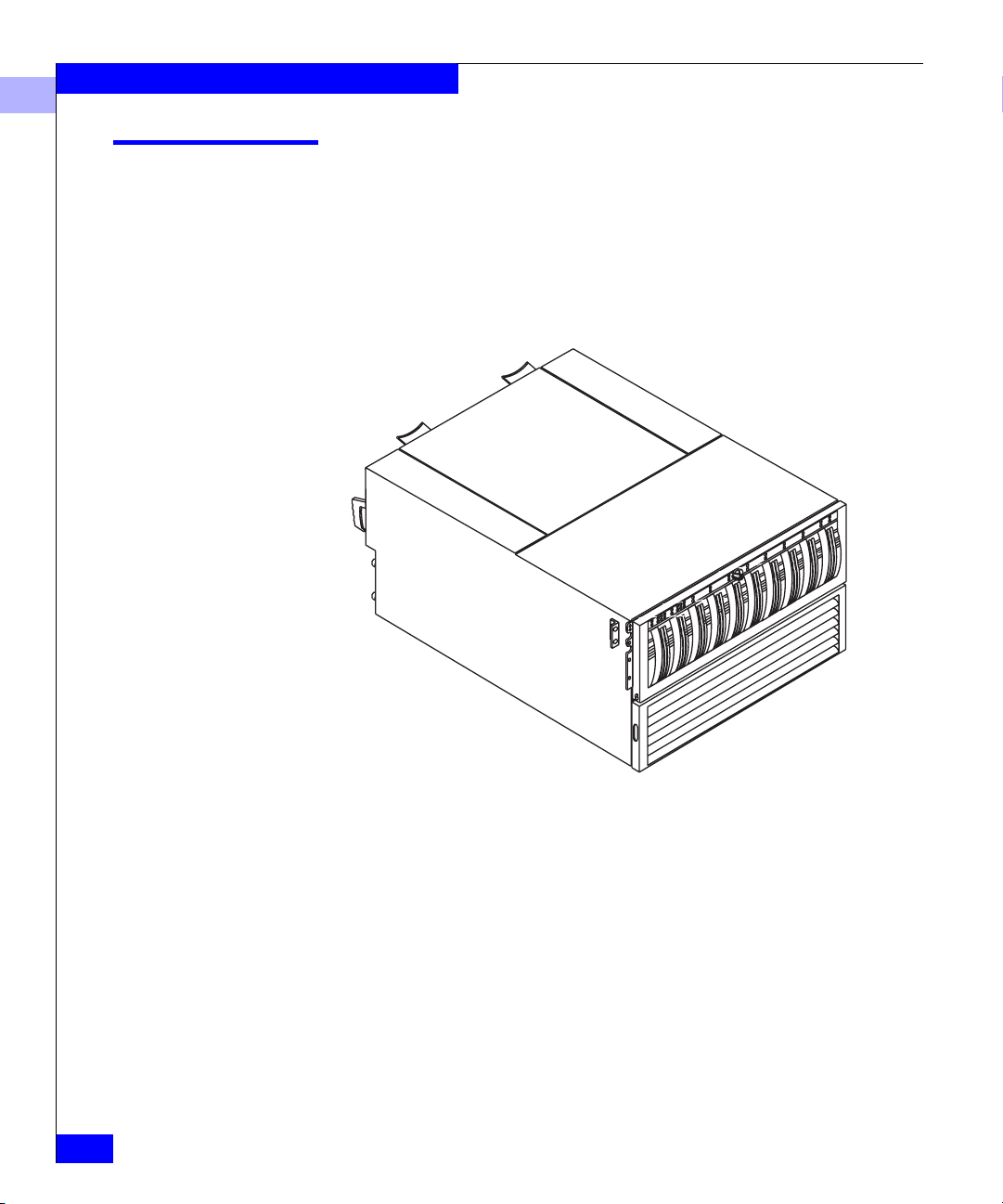
Figure 1-1 DAE
Using its interface, with simple FC-AL serial cabling, the FC4500
DPE can support up to 11 DAEs A DAE is a basic enclosure without a
storage processor (SP). The FC4500 and 11 DAEs support up to 120
disk modules in a single disk-array file storage system.
EMC Fibre Channel Disk-Array Processor Enclosure (DPE) Hardware Reference
Page 15

About the Rackmount Disk-Array Processor Enclosure
You can place the DAEs in the same cabinet as the DPE, or in one or
more separate cabinets. The DPE connects to the external Fibre
Channel environment using GBIC connectors on the storage
processor. High-availability features are standard.
The EMC Access Logix™ option provides Storage Group
functionality for the FC4500 DPE.
1
Introduction
1-3
Page 16

About the Rackmount Disk-Array Processor Enclosure
1
DPE Components
The DPE components include:
• A sheet-metal enclosure with a midplane, front door, and SP fan
pack cover
• One or two SPs
• One or two link control cards (LCCs)
• Up to ten disk modules
• One or two power supplies
• One drive fan pack
• One SP fan pack
Any unoccupied slot (SP, LCC, disk module, or power supply) has a
filler module to maintain air flow and compliance with
electromagnetic interference (EMI) standards.
The SPs, LCCs, disk modules, power supplies, fan packs, and filler
modules are customer-replaceable units (CRUs), which you can add
or replace without tools while the DPE is powered up.
1-4
The high-availability features for a DPE include:
• Second SP and LCC
• Second power supply
• Standby power supply (SPS) (See “Related Documentation” on
page xi.)
A second SP (with required second LCC) provides continued access
to the DPE and any connected DAEs if the first SP or LCC fails. The
second SP can improve performance and connects easily to a second
server.
The disk drives are FC-AL compliant and support dual-port FC-AL
interconnects through the two LCCs and their cabling.
Enclosure
EMC Fibre Channel Disk-Array Processor Enclosure (DPE) Hardware Reference
The enclosure is a sheet-metal housing with a front panel, a
midplane, front door, and slots for the SPs, LCCs, disk modules,
power supplies, and fan packs.
The following figures show the DPE components. Details on each
component follow the figures. If the enclosure provides slots for two
Page 17
About the Rackmount Disk-Array Processor Enclosure
identical components, the component in slot A is called
component-name A. If there is a second component, it is in slot B and is
called component-nameB, as follows.
Component Name in Slot A Name in Slot B
SP SP A SP B
LCC LCC A LCC B
Power supply PS A PS B
If you have one power supply, it can be in either slot A or slot B. If
you have one SP and one LCC, they can be in either slot A or B, but
not mixed.
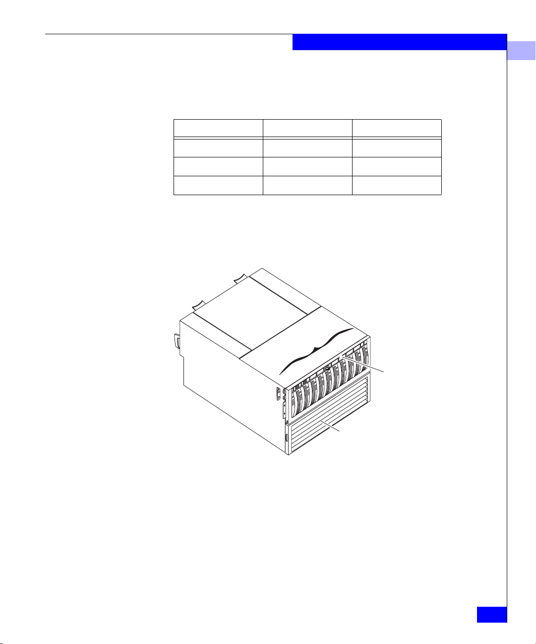
s
e
l
u
d
o
m
k
s
i
D
1
0
5
4
3
2
9
8
7
6
Front
door
1
Figure 1-2 DPE Front View
SP fan pack cover
DPE Components
1-5
Page 18
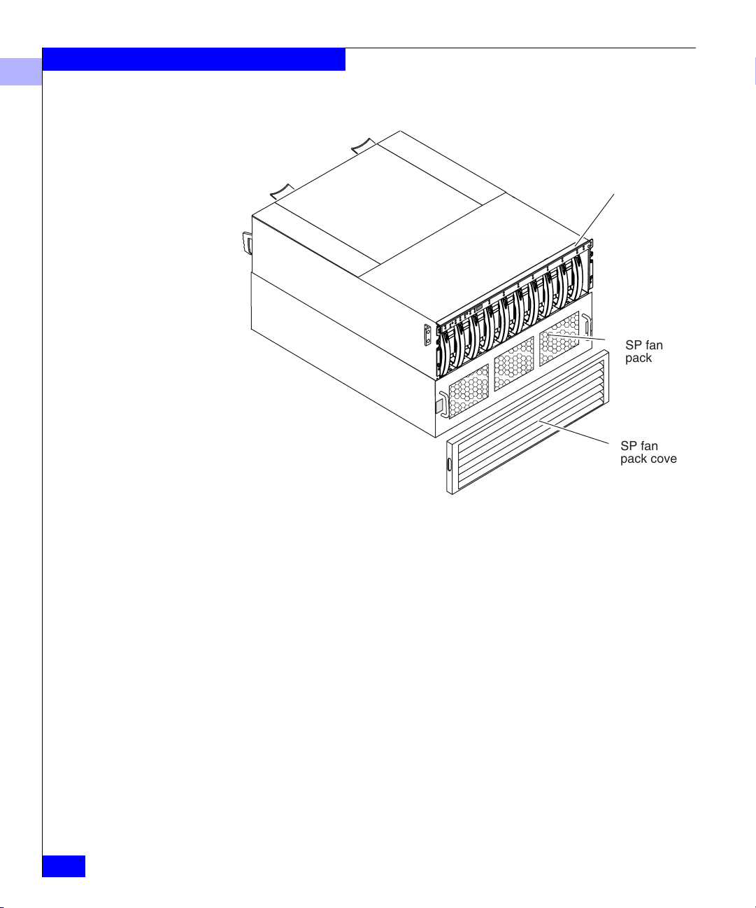
About the Rackmount Disk-Array Processor Enclosure
1
Front panel with door
removed for clarity
SP fan
pack
SP fan
pack cover
1-6
Figure 1-3 DPE Front View with SP Fan Cover and Door Removed
EMC Fibre Channel Disk-Array Processor Enclosure (DPE) Hardware Reference
Page 19
About the Rackmount Disk-Array Processor Enclosure
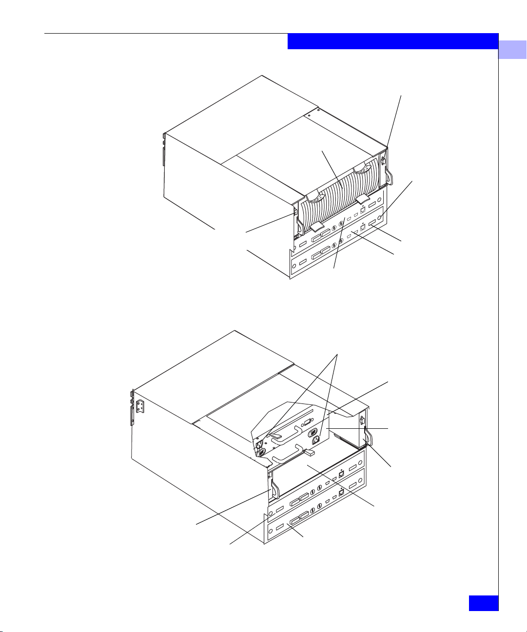
Drive fan pack
1
LCC A with expansion
connector (marked EXP)
SP retaining screw
(2 per SP)
LCC B with expansion
connector (marked EXP)
Figure 1-4 DPE Back View
LCC B
SP B
SP ejector (2 per SP)
SP A
SP B
ac line cord
connectors
Power supply
PS A
Power supply
PS B
LCC A
Location of DPE EMI
rating label - Class A
SP A
Figure 1-5 DPE Back View with Drive Fan Pack Removed
DPE Components
1-7
Page 20
About the Rackmount Disk-Array Processor Enclosure
1
SP A works with LCC A to run SP A’s disk modules; SP B works with
LCC B to run SP B’s disk modules.
Front Panel
Enclosure address light
(0 for a DPE)
Midplane
Disk module status lights
(two per module)
Check
1023 4 5 6 7 8 9
Active
Check
The front panel contains the enclosure address (EA) light, two status
lights for each disk module slot, and two DPE status lights. All lights
are visible with the front door closed.
The enclosure address light displays the enclosure address setting for
the DPE, which is always 0. This address cannot be changed.
The DPE status lights are described in the “Monitoring DPE status”
section in Chapter 3.
The midplane distributes power and signals to all the enclosure
components. All CRUs except the fan packs plug directly into
midplane connectors.
DPE status lights
Power
1-8
EMC Fibre Channel Disk-Array Processor Enclosure (DPE) Hardware Reference
Page 21
Locking latch
with key
About the Rackmount Disk-Array Processor Enclosure
1
The front door must be closed for the
DPE to be EMI compliant. Opening
the door to access the disk modules is
a service procedure.
Figure 1-6 Front Door
Storage Processors (SPs)
The front door has a locking latch and an EMI shield. The latch is a
push button with a removable locking key that you can use in any
DPE or DAE. When the door is open, you can remove or install disk
modules.
The SP is the DPE’s intelligent component. It defines the DPE and
differentiates the DPE from a DAE. An SP is a printed-circuit board
with dual in-line memory modules (DIMMs), a bezel with status
lights, and securing latches. The following figure locates the SP ports,
the status lights, the location of the DIMMs, and the FC-AL ID rotary
switches.
DPE Components
1-9
Page 22
About the Rackmount Disk-Array Processor Enclosure
1
Connectors for DIMMS
Captive retaining
screw (2 per SP)
Release lever
(2 per SP)
Port A (with optical GBIC)
Port B (with optical GBIC)
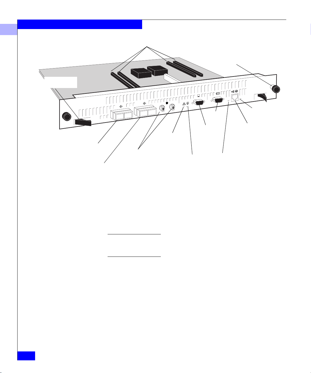
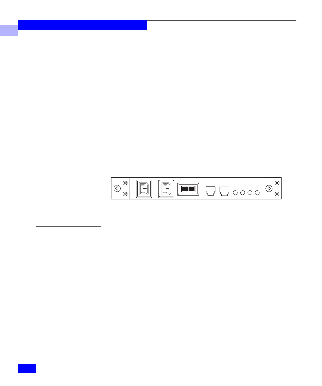
Figure 1-7 SP Back Panel
Speed light
Network/RJ45
connection
reserved for
future use
Check Light
(amber)
FC-AL ID switches
(required only for Fibre
Channel Arbitrated
Loop environment)
Console
Active light
(green)
SPS
Link/activity light
As shown in the figure, the SP has 4 connectors for DIMMs that
comprise both read and write caches. These DIMMs come in 128-,
256-, or 512-Mbyte capacity. Memory allocation is handled by
Navisphere
® Manager or another Navisphere array management
utility.
When the DPE is configured to operate in a fabric environment, only one of
the SP ports (A or B) can be used to connect to the external Fibre Channel
environment.
The SP has two Fibre Channel ports (A and B) referred to as the SP
front end, for connecting to the external Fibre Channel environment.
It also has two rotary switches for setting the FC-AL address ID when
operating in a Fibre Channel Arbitrated Loop environment.
1-10
The SP connects to disk modules and to its corresponding LCC via an
internal FC-AL. SP A connects to LCC A, and SP B to LCC B. The
SP-LCC interface is called the SP back end.
The SP also has an Console connector (with a terminal icon), a
connector for communication with the standby power supply,
marked SPS, and a LAN connection. Each SP has four status lights
EMC Fibre Channel Disk-Array Processor Enclosure (DPE) Hardware Reference
Page 23
visible from the back of the DPE. For a definition of these light colors,
see the “Monitoring DPE Status” section in Chapter 3.
If a DPE has one SP, you can install a second one while the DPE is
running.When both SPs are installed, you can replace either SP while
the DPE is running. You should never attempt to replace any of the
SP’s components, except the memory modules and GBICs.
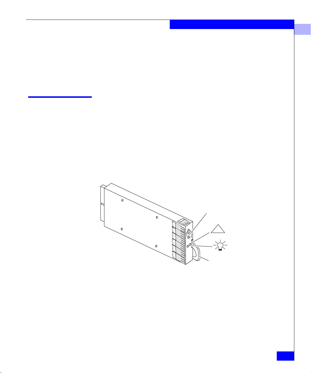
Link Control Cards (LCCs)
A link control card (LCC) is a CRU in an enclosure that connects Fibre
Channel signalling to the disk modules. The LCC provides:
• Fibre channel connectivity between the SP, disks, and other
enclosures
• Bypass capability for faulted or missing units
• Monitor and control of the enclosure elements
About the Rackmount Disk-Array Processor Enclosure
1
Figure 1-8 LCC
Each LCC independently monitors the environmental status of the
entire DPE, using a microcomputer-controlled CRU monitor. The
CRU monitor communicates status to the SP server using special
protocols. These protocols let the SP poll DPE status and send
commands that control the port LCC bypass circuits and the
disk-module check lights.
EXP
Latch
Link Control Cards (LCCs)
Expansion FC-AL
cable connector
Check light
!
(amber)
Active light
(green)
1-11
Page 24
About the Rackmount Disk-Array Processor Enclosure
1
Each LCC has two status lights visible from the back of the DPE. For
definitions of these light colors, see the “Monitoring DPE Status”
section in Chapter 3.
A latch on the LCC locks it into place to ensure proper connection to
the midplane. You can add or replace an LCC while the DPE is
powered up.
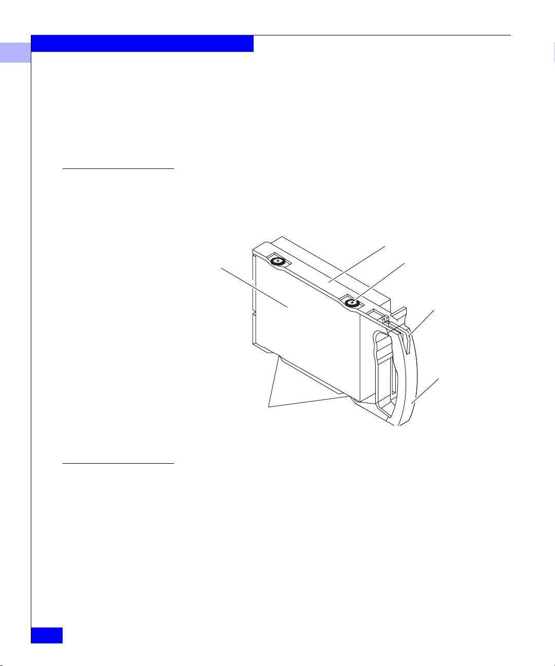
Disk Modules
Disk Drives
Each disk module (see figure below) consists of a Fibre Channel disk
drive in a carrier assembly. You can add or remove a disk module
while the DPE is powered up.
Disk drive
Figure 1-9 Disk Module
The disk drives are 3.5-inch FC-AL drives that conform to the
following standards:
Carrier
Shock mount (4)
Latch
Handle
ESD clip (2)
1-12
• SFF-8067
• Fibre Channel Arbitrated Loop (FC-AL)
• FC-AL Private Loop Direct Attach (PLDA) profile
The disk module slots in the enclosure accommodate drives with
heights of either 2.54 cm (1.0 inch) or 4.06 cm (1.6 inches). You can
combine drives of either height, and from different manufacturers,
EMC Fibre Channel Disk-Array Processor Enclosure (DPE) Hardware Reference
Page 25
About the Rackmount Disk-Array Processor Enclosure
within the same DPE, subject to the restrictions imposed by the Core
Software running in the DPE’s SPs.
1
Drive Carrier
Power Supplies
The disk-drive carrier is a plastic assembly that slides into the
enclosure slot guides and midplane connectors. It has a handle with a
latch and electrostatic discharge (ESD) clips, which connect to the
drive’s head-disk assembly. The latch holds the disk module in place
to ensure proper connection with the midplane.
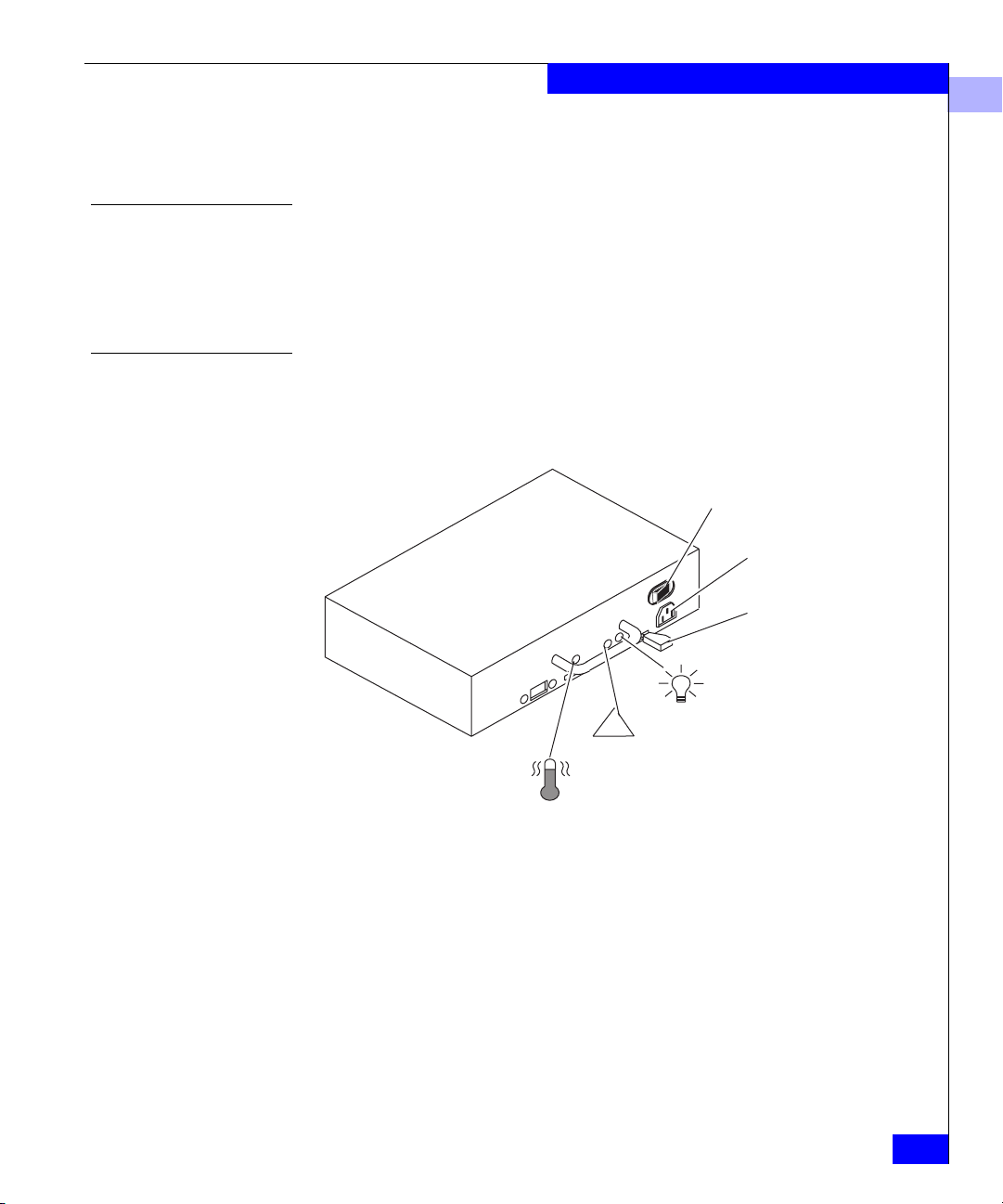
The power supplies (see figure below) are located behind the drive
fan pack. With two power supplies, the top supply is installed
inverted with respect to the bottom supply.
On/Off switch and
circuit breaker
Ac line cord
connector
Latch
Active light
(green)
Check light
!
(amber)
Figure 1-10 Power Supply
Each power supply is an auto-ranging, power-factor-corrected,
multi-output, off-line converter with its own line cord and on/off
switch. Each supply supports a fully configured DPE and shares load
currents with the other supply, if it is present. The drive and LCC
voltage lines have individual soft-start switches that protect the disk
drives and LCCs if you install them while the DPE is powered up. A
CRU with power-related faults will not adversely affect the operation
of any other CRU.
Cooling Check
light (amber)
Link Control Cards (LCCs)
1-13
Page 26
About the Rackmount Disk-Array Processor Enclosure
1
Each power supply has status lights. These status lights are partially
visible through the drive fan pack, and fully visible with the drive fan
pack removed. The status lights are described in the “Monitoring
DPE Status” section of Chapter 3.
A latch on the power supply locks it into place to ensure proper
connection to the midplane. You can add or remove one power
supply in a highly available DPE while the DPE is powered up.
Standby Power Supply (SPS)
Figure 1-11 SPS
Drive Fan Pack
Disk configurations that use write caching, such as RAID 5, require a
standby power supply (SPS) to prevent data loss during a power
failure. Data is maintained after a power loss.
One or two SPS units fit beneath the DPE and maintain power until
write cache data can be safely stored to the disk. Installing an SPS and
cabling it to the DPE are explained in the manual DC Standby Power
Supply (SPS) Installation (014002887).
The drive fan pack (see Figure 1-11) cools the disk modules, power
supplies, and LCCs in the DPE. A separate pack, described next, cools
the SPs. The drive fan pack contains three fans that draw ambient
room air through the front door, across the drive modules, and
through the midplane and power supplies. The drive fan pack
connects directly to both power supplies, and either supply can
power it. The fans operate at a lower voltage and speed during
normal operation to minimize acoustic noise. If a fan fails, the voltage
and speed of the remaining fans increase to compensate, resulting in
higher acoustic noise.
1-14
EMC Fibre Channel Disk-Array Processor Enclosure (DPE) Hardware Reference
Page 27
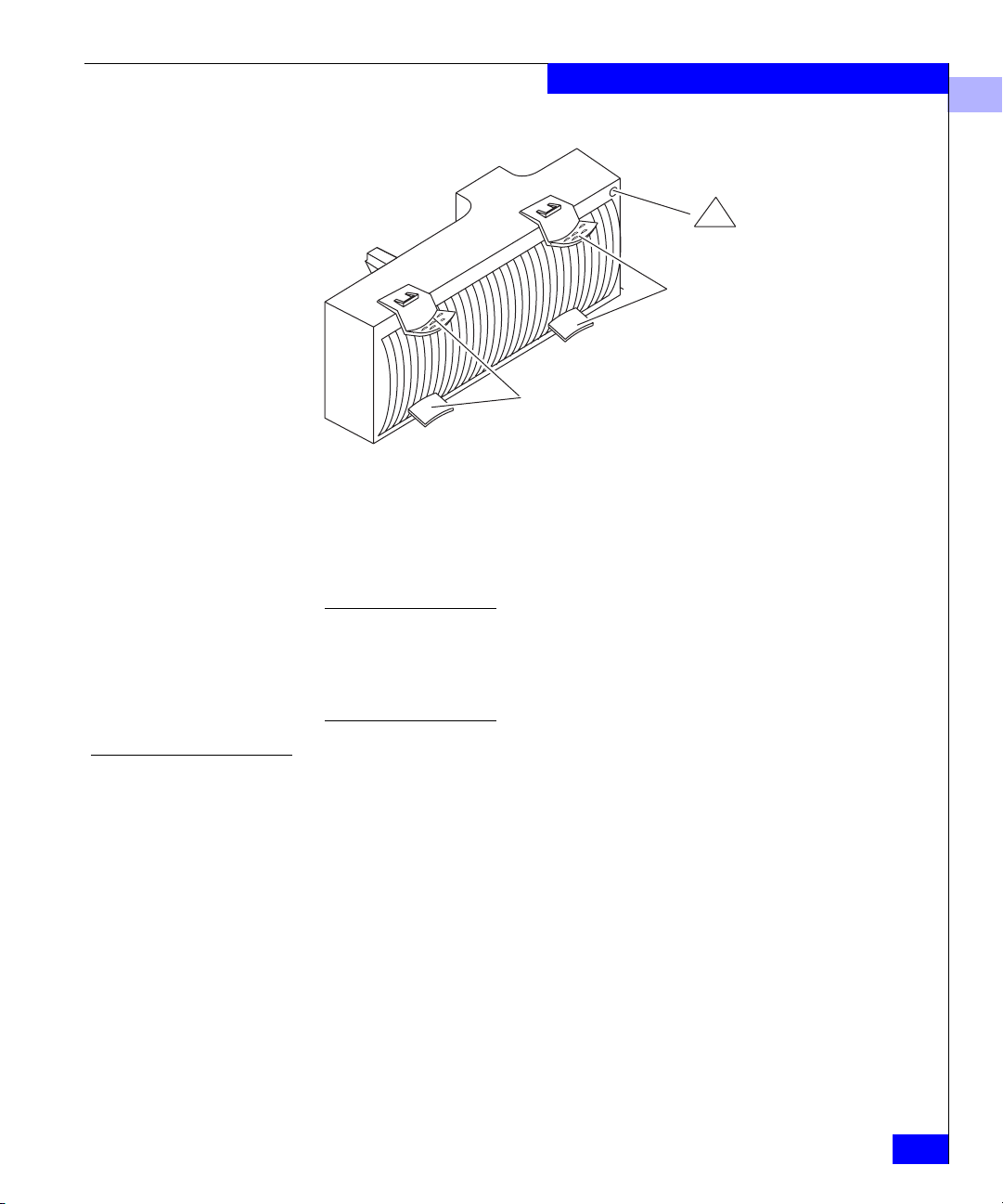
Figure 1-12 Drive Fan Pack
The drive fan pack has one status light. The status light is described
in the “Monitoring DPE Status” section of Chapter 3.
Latches on the drive fan pack hold the pack in place.
About the Rackmount Disk-Array Processor Enclosure
Check light
!
(amber)
Latches
Latches
1
SP Fan Pack
You can remove the drive fan pack while the DPE is powered up. While the
pack is removed, the cooling check light on each power supply flashes. If the
pack is removed for more than approximately two minutes, the disk modules
and SPs power down. The disk modules and SPs power up when you
reinstall the drive fan pack.
The SP fan pack (see Figure 1-12) cools the SPs. It contains three fans
that draw ambient room air through the SP fan pack cover, through
the midplane, and across the SPs. The SP fan pack connects to the
DPE midplane via an internal cable, and either supply can power it.
The fans operate at a lower voltage and speed during normal
operation to minimize acoustic noise. If a fan fails, the voltage and
speed of the remaining fans increase to compensate, resulting in
higher acoustic noise.
Link Control Cards (LCCs)
1-15
Page 28
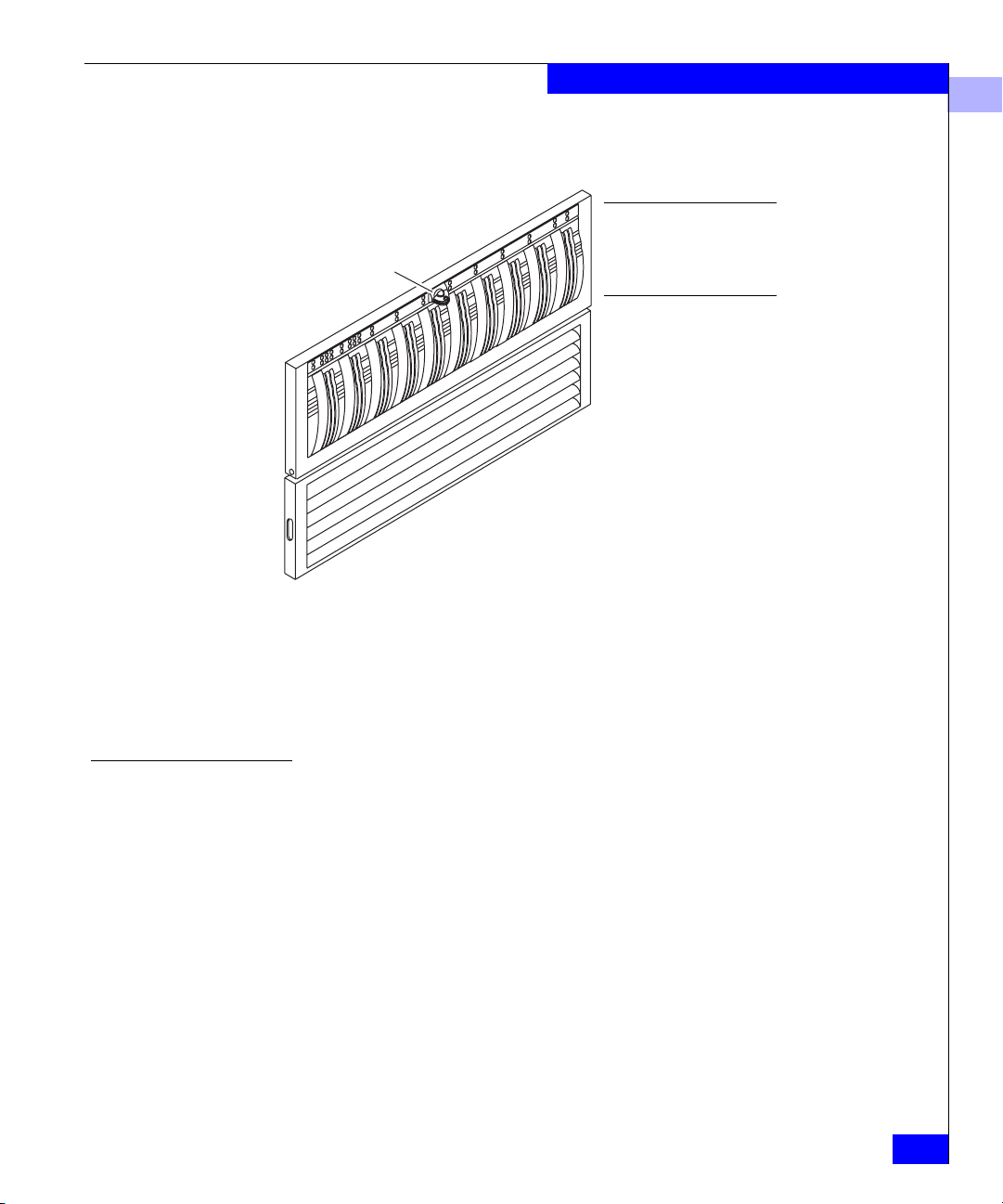
About the Rackmount Disk-Array Processor Enclosure
1
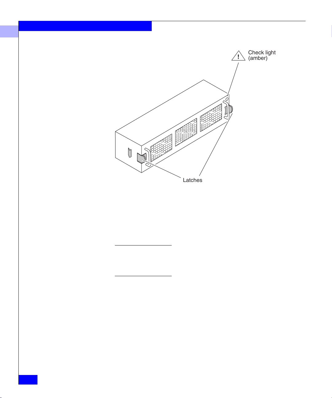
Check light
!
(amber)
Latches
Figure 1-13 SP Fan Pack
1-16
Latches on the SP fan pack hold the pack in place.
The SP fan pack has one status light visible when the SP fan pack
cover is removed. The status light is described in the “Monitoring
DPE Status” section of Chapter 3.
You can remove the SP fan pack while the DPE is powered up. If the pack is
removed for more than approximately two minutes, the SPs and disk
modules power down. The SPs and disk modules power up when you
reinstall the SP fan pack.
EMC Fibre Channel Disk-Array Processor Enclosure (DPE) Hardware Reference
Page 29
Redundancy in Configurations
Mirrored storage-system write caching requires:
• Two SPs with equal memory of at least 128 Mbytes
• Two power supplies
• Two LCCs in the DPE and each DAE
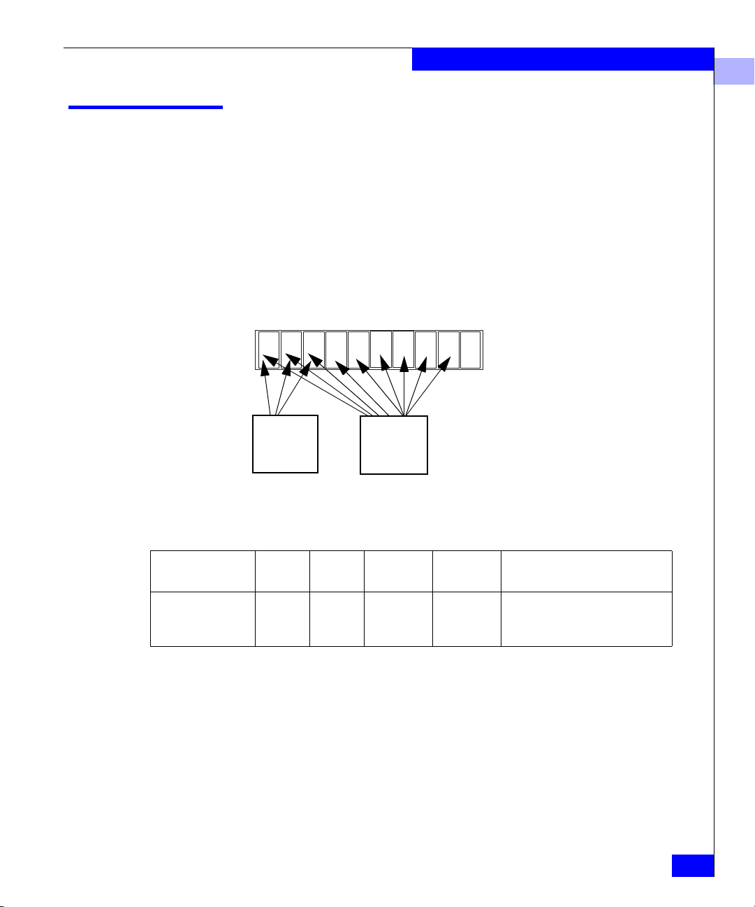
• Disks in slots 0:0 through 0:8
• SPS (standby power supply) with a fully charged battery
DPE Rackmount
0123456789
About the Rackmount Disk-Array Processor Enclosure
1
Database
drives for
LIC
(0 thru 2)
The following table describes the DPE’s high-availability
configurations.
Configuration SPs LCCs
Maximum - HA 2
2
2
2
These configurations provide more redundancy, and therefore a
higher degree of system availability. The drive fan packs and SP fan
pack provide redundant cooling for all the configurations listed
above.
Vault
drives for
caching
(0 thru 8)
Power
supplies
2
2
Disk
modules SPSs
3 or more
9 or more
0 (no write caching)
2 (high-availability write caching)
Redundancy in Configurations
1-17
Page 30

About the Rackmount Disk-Array Processor Enclosure
1
What Next?
Continue to the next chapter, which explains how to install a DPE.
1-18
EMC Fibre Channel Disk-Array Processor Enclosure (DPE) Hardware Reference
Page 31

2
Installing a Rackmount
DPE
This chapter describes the DPE installation requirements and
procedures. Topics in this chapter include:
• Requirements......................................................................................2-1
• Installing a DPE in a Cabinet............................................................2-3
• DPE Powerup and Initialization....................................................2-16
• DPE Powerdown..............................................................................2-16
• Binding Disk Modules into Groups ..............................................2-18
Requirements
Site Requirements
Power To deter mine a DPE’s power requirements, use the power rating on
This section explains site, cabling, and addressing requirements.
For proper DPE operation, the installation site must conform to
certain environmental specifications. These are detailed below and in
Appendix A.
the enclosure label. This rating is the maximum power required for a
fully loaded enclosure. The input current, power (VA), and
dissipation for the DPE are based on the maximum capability of the
power supplies and cooling system to provide internally regulated
power. Typical values will be less, depending on the number and
manufacturer of disk drives. These values represent either the values
for the power cord of a DPE with a single power supply, or the total
values shared by the line cords of two power supplies in the same
DPE, with the division between the power cords and supplies at the
current sharing ratio. If one of the two power supplies fails, the
Installing a Rackmount DPE
2-1
Page 32

Installing a Rackmount DPE
2
remaining supply and cord support the full load. You must use a
rackmount cabinet with ac power distribution, and have main branch
ac distribution that can handle these values for the number of DPEs
and DAEs that you will interconnect.
Cooling The ambient temperature specification is measured at the front door
inlet. The site must have air conditioning of the correct size and
placement to maintain the specified ambient temperature range. The
air conditioning must be able to handle the BTU requirements of the
DPEs and any connected DAEs.
Cabling Requirements
Use optical cables for connections to the external Fibre Channel
environment. Use a copper cable only (not an optical cable) to
connect a DPE to a DAE. The optical cables connect to the optical
GBIC on the SP.
DPE and DAE interconnections should maintain LCC consistency.
That is, one FC loop should connect the DPE’s SP A (which connects
internally to LCC A) and each DAE’s LCC A. The other FC loop
should connect the DPE’s SP B (which connects internally to LCC B)
and each DAE’s LCC B.
Do not leave an unused (that is, dangling) cable connected to any
Fibre Channel port because it may cause excess noise on the Fibre
Channel.
Addressing Requirements
The addressing requirements vary depending on the environment,
fibre port (fabric), or the fibre loop (FC-AL).
Fabric Environments In a fabric environment, the DPE is addressed using the Source_ID
(SID) and the Enclosure Address (EA).
Source_ID
The Source_ID (SID) is a value that a switch in the external Fibre
Channel environment automatically assigns.
Enclosure Address (EA)
Each DPE and DAE on a back-end loop needs a unique enclosure
address (EA) that identifies the enclosure and determines disk
module addresses. The DPE has a fixed EA of 0 that you cannot
change. If you cable any DAEs to the DPE, you might want to set the
nearest DAE’s EA to 1, the next to 2, and so on. The enclosure address
is displayed in lights visible behind the front door.
2-2
EMC Fibre Channel Disk-Array Processor Enclosure (DPE) Hardware Reference
Page 33

Installing a Rackmount DPE
Loop Environments In an FC-AL environment, the DPE is addressed using the FC-AL
address ID and the enclosure address (EA).
Fibre Channel Arbitrated Loop Address ID (FC-AL Address ID)
Each node (such as an SP) on the Fibre Channel front-end loop must
have a unique Fibre Channel arbitrated loop address ID (FC-AL
address ID). The FC-AL protocol translates the FC-AL address ID into
an 8-bit arbitrated loop physical address (ALPA). You set the SP
FC-AL address ID using switches, as explained later in this chapter.
Enclosure Address (EA)
Each DPE and DAE on a back-end loop needs a unique enclosure
address (EA) that identifies the enclosure and determines disk
module addresses. The DPE has a fixed EA of 0 that you cannot
change. If you cable any DAEs to the DPE, you might want to set the
nearest DAE’s EA to 1, the next to 2, and so on. The enclosure address
is displayed in lights visible behind the front door.
Installing a DPE in a Cabinet
The cabinet in which you will install the DPE(s) must have a full
earth ground to provide reliable grounding. Also, the cabinet should
have its own switchable power distribution. If any DPE you will
install has two power supplies, we suggest that you use a cabinet that
has dual power distribution units, one on each side.
2
WARNING
The rackmount DPE is heavy and should be installed into a rack by
two people. To avoid personal injury and/or damage to the
equipment, do not attempt to lift and install the DPE into a rack
without help from another person.
WARNING
WARNUNG: Das Rackmount-DPE ist schwer und sollte nur von
zwei Personen in einem Gehäuse installiert werden. Zur Vermeidung
von körperlichen Verletzungen und/oder der Beschädigung des
Gerätes, bitte die DPE nicht ohne die Hilfe einer zweiten Person
anheben und einbauen.
We recommend that you use cabinet anti-tip devices, especially if you
are installing or removing a DPE in the upper half of the cabinet
when the lower half is empty.
Installing a DPE in a Cabinet
2-3
Page 34

Installing a Rackmount DPE
2
You install each DPE on two L-shaped mounting rails connected to
the cabinet’s vertical channels.
• Installing the cabinet itself is explained in another manual. For
some standard cabinets, the information is in a cabinet
installation manual shipped with the cabinet.
• Installing the mounting rails in the cabinet is explained in a rails
installation manual shipped with the rails.
Installing DPEs on the Mounting Rails in the Cabinet
1. In the cabinet, set the main circuit breaker switches to the off
position.
2. Attach the clip of the ESD wristband (strap) to bare metal on the
cabinet, and put the wristband around your wrist with the metal
button against your skin.
3. With help, lift the DPE and, from the front of the cabinet, slide the
DPE onto the lowest rails.
2-4
EMC Fibre Channel Disk-Array Processor Enclosure (DPE) Hardware Reference
Page 35

4. Open the DPE front door as shown below.
Installing a Rackmount DPE
2
Latch
Key
To unlock, turn
180o clockwise.
A.
If the door is locked:
Insert the key in the door’s latch.
Turn the key 180o clockwise.
Remove the key from the latch, if desired. (If you do not
remove the key, it may fall to the floor after you open the door.)
Latch
B.
Depress the door latch.
C.
Lower the door until it is
perpendicular to the
front of the enclosure.
Figure 2-1 Opening the Front Door
CAUTION: Do not force the door open.
If the door snaps off its hinges,
reinstall it by positioning it at a 45
o
angle to the enclosure, and snapping it
into the hinge openings.
Installing a DPE in a Cabinet
2-5
Page 36

Installing a Rackmount DPE
2
5. Secure the DPE to the vertical channels of the cabinet as shown
next.
Fasten the front of the enclosure to
the front channels in the cabinet
using two screws (one per side).
NOTE: Only one hole in the enclosure bracket aligns
with a hole on the channel. The hole you use depends
on where the rails are mounted in the cabinet.
Figure 2-2 Securing the DPE to the Cabinet Front Channel
2-6
6. Secure the rear mounts of the DPE to the back channels of the
cabinet, as shown in Figure 2-3.
EMC Fibre Channel Disk-Array Processor Enclosure (DPE) Hardware Reference
Page 37

Installing a Rackmount DPE
Fasten the bracket at the back
of each rail to the bottom left
and right of the DPE using two
screws (one per side).
2
Figure 2-3 Securing the DPE to the Cabinet Back Channel
7. Close the DPE front door, as shown in Figure 2-4.
The door must be closed for EMI compliance. Open the door only to
service the DPE.
Installing a DPE in a Cabinet
2-7
Page 38

Installing a Rackmount DPE
_
2
A. Raise the door until
it latches into place.
B. If desired, lock the door as follows:
Insert the key in the door’s latch.
Turn the key 180o counterclockwise.
Remove the key, if desired.
Latch
Figure 2-4 Closing and Locking the Front Door
Latch
Key
To lock, turn 180o
counterclockwise.
2-8
EMC Fibre Channel Disk-Array Processor Enclosure (DPE) Hardware Reference
Page 39

Installing a Rackmount DPE
8. Perform this step only if you are installing the DPE into an FC-AL
environment. Otherwise, continue to the next step.
To communicate in an FC-AL environment, each SP requires a
unique FC-AL address ID (the front-end address). The FC-AL
protocol translates the address ID into an 8-bit arbitrated loop
physical address (ALPA). Valid Fibre Channel address IDs range
from 0 through 125 (decimal) (0 through 7D hexidecimal).
Each SP’s Fibre Channel address ID must be unique on the Fibre Channel
loop.
At the back of the DPE, for each SP use the SP FC-AL ID switches
(see Figure 2-5) to set the address ID.
2
Installing a DPE in a Cabinet
2-9
Page 40

Installing a Rackmount DPE
2
0
1
2
3
4
5
6
7
8
FC-AL address ID
(decimal) Left switch setting Right switch setting
000
101
0
1
F
E
D
C
B
A
2
3
4
5
6
7
9
8
2-10
.
.
.
.
.
.
15 0 F
16 1 0
.
.
.
.
.
.
31 1 F
32 2 0
.
.
.
.
.
.
125 7 D
Figure 2-5 SP Fibre Channel Arbitrated Loop Address ID Switches (Back of SP)
EMC Fibre Channel Disk-Array Processor Enclosure (DPE) Hardware Reference
.
.
.
.
.
.
.
.
.
Page 41

9. For access to the ac power inlets, you must remove the drive fan
pack. Remove the drive fan pack as shown below.
Figure 2-6 Removing the Drive Fan Pack
Installing a Rackmount DPE
A.
Grasp the latches on the drive fan pack.
B.
Squeeze the latches together and
pull the pack from the enclosure.
2
10. From the back of the cabinet, plug the ac line cord into each
power supply and turn on the supply’s power, as shown in Figure
2-7.
Installing a DPE in a Cabinet
2-11
Page 42

Installing a Rackmount DPE
2
ac inlet
Bottom power supply Top power supply
ac power cord
ac inlet
(right-angle plug)
Power switch and
circuit breaker
Figure 2-7 Plugging the AC Line Cord into the Power Supply and Turning on the
Power Switch
ac power cord
(right-angle plug
Channel
Channel
Power switch and
circuit breaker
2-12
EMC Fibre Channel Disk-Array Processor Enclosure (DPE) Hardware Reference
Page 43

Installing a Rackmount DPE
11. Reinstall the drive fan pack on the back of the DPE.
You can install the drive fan pack in either horizontal position.
However, for a consistent image with DAEs, we recommend you
install it with the check light in the upper right corner, as shown
below.
Check light
A. Grasp the latches on the drive fan
module.
B. Squeeze the latches together and
gently push the module into the
enclosure until it clicks into place.
2
Figure 2-8 Installing the Drive Fan Module
12. Attach the Fibre Channel cable from SP A and/or B Port to the
external environment) as shown next.
When working with optical cables, observe the following precautions:
• Keep the covers on all optical cables and optical GBICs until
you are ready to insert the cables. The covers protect the cables
and connectors, and prevent foreign particles, such as dust,
from entering and affecting the connection.
• Do not leave an unused (that is, dangling) cable, connected to
an SP port because it may cause excess noise on the loop.
Installing a DPE in a Cabinet
2-13
Page 44

Installing a Rackmount DPE
2
• Avoid tight bends. If you need to make a 90º bend, do it over 6
to 12 inches.
• Do not use optical cables to support weight. That includes
long cable runs without support.
• Do not pull long runs of cable. It is best to lay the cable in
place or pull only a few feet at a time.
• Run the cables so that they are not stepped on or rolled over
by anything.
A. Remove the protective covers
from each optical GBIC
connector and each fibre
optic cable.
B. Plug the fibre optic cable into
Port A and/or Port B on the
SP.
Cover
2-14
Optical GBIC
connector
B
A
Figure 2-9 Attaching Optical Cables to a DPE
EMC Fibre Channel Disk-Array Processor Enclosure (DPE) Hardware Reference
Cover
Fibre optic cable
Page 45

Installing a Rackmount DPE
13. To expand this DPE, cable its LCC EXP connector to the next
corresponding DAE’s PRI (primary) connector, as shown below.
IMPORTANT: Do not connect a cable between
an LCC in slot A and an LCC in slot B.
2
Primary
connector
Copper cable
Expansion
connector
Figure 2-10 Cabling a DPE to a DAE
14. If the DPE has another SP, LCC, and DAE, connect the DPE’s
other LCC and the DAE’s other LCC as above.
15. To connect additional DAEs, attach a copper cable between the
DAE’s LCC EXP connector and the next DAE’s PRI (primary)
connector (detailed in the DAE Installation Manual). If this DAE
and the next DAE have a second LCC, repeat this step for the
second LCC.
16. Make sure all the slots in the DPE and in each DAE contain either
CRUs or filler modules. At least two disk modules are required in
the DPE. We recommend inserting them in slots 0 and 1.
A. Plug one end of a copper cable
into the expansion (EXP)
connector on an LCC in the DPE.
B. Tighten the two thumb screws
on the cable’s connector.
C. Plug the other end of the copper
cable into the primary (PRI)
connector on the matching LCC
in the DAE.
D. Tighten the two screws on the
cable’s connector.
17. In the cabinet, set the main circuit breaker switches to the on
position.
The DPE and any DAEs in the cabinet will power up.
Installing a DPE in a Cabinet
2-15
Page 46

Installing a Rackmount DPE
2
DPE Powerup and Initialization
The only power switches on a DPE are those on the power supply,
which are normally covered by the drive fan pack. As a result, a DPE
is always active.
When ac power is initially applied to a DPE, the disk drives power up
and spin up in a specified sequence. The maximum delay is 48
seconds for the last drive to start spinning in a DPE, and 84 seconds
for the last drive to start spinning in a DAE. The same delays occur
when you insert a drive while a DPE is powered up.
DPE Powerdown
If DPE (with an SPS option) is powered down abnormally (e.g., a
brown out or ac failure), data is saved to the storage-system vault
disks, and not lost. However, when the DPE is powered back up
again, it may take longer to come online.
2-16
Turning Off the Power 1. Stop all I/O activity to the DPE.
Stopping the I/O allows the SP to destage cache data, and may take some
time. The length of time will be based on criteria such as the amount of cache,
the amount of data in the cache, the type of data in the cache, and the target
location on the disks.
2. If the server connected to the DPE is running the UNIX®
operating system, unmount the file systems.
3. Shut off power to the ac distribution strips that supply the DPE.
The power in the distribution strips may be controlled by a circuit
breaker located inside the cabinet (if the cabinet has such
breakers) or externally to the cabinet.
EMC Fibre Channel Disk-Array Processor Enclosure (DPE) Hardware Reference
Page 47

Installing a Rackmount DPE
Power switches
ac distribution strips
SP B
SP A
SPS power switches
4. If the DPE has SPS protection, use the power switch on each SPS
to turn off power.
2
When you turn off power to a storage system with an SPS, the On
Battery light may come on for a maximum of 90 seconds during
which time the DPE will continue to run. This is a normal
condition. Wait for the light to go off and the fans to stop before
proceeding with further service to the storage system.
Never remove the fan pack and then shut off the power supply to shut
down an DPE. Doing that effectively cuts out the SPS and write cache
data cannot be saved to the vault drives, which results in a cache dirty
condition (data loss). When that happens, LUNs become inaccessible and
the unsolicited event log displays a message similar to:
“Enclosure 0 Disk 5 0x90a (Can’t Assign - Cache Dirty)
0 0xafb40 0x14362c.” Navisphere Manager or Supervisor will show
that the inaccessible LUNs are unowned. Contact your service provider if
this situation occurs. The LUNs may need to be unbound and rebound.
Powering On Reverse the steps in the previous section to power up the DPE.
DPE Powerdown
2-17
Page 48

Installing a Rackmount DPE
2
Binding Disk Modules into Groups
After cabling a DPE and any DAEs, you can bind disk modules into
groups and set up storage-system caching. To bind disk modules and
set up caching, you will use a utility described in the server setup or
installation manual.
2-18
EMC Fibre Channel Disk-Array Processor Enclosure (DPE) Hardware Reference
Page 49

3
Servicing and
Upgrading a DPE
This chapter describes how to monitor DPE status, handle CRUs, and
replace or add a CRU. Topics in this chapter include:
• Monitoring DPE Status .....................................................................3-1
• Handling CRUs ..................................................................................3-4
• Power Issues and CRUs ....................................................................3-4
• Avoiding Electrostatic Discharge (ESD) Damage..........................3-6
• Precautions When Removing, Installing, or Storing CRUs .........3-7
• Precautions When Handling Optical Cables .................................3-8
• Replacing or Adding a Disk Module ..............................................3-9
• Replacing the SP Fan Pack..............................................................3-14
• Replacing an Optical GBIC.............................................................3-17
• Removing an SP or an SP Filler Module.......................................3-21
• Installing or Replacing an SP Memory Module ..........................3-24
• Installing an SP or SP Filler Module..............................................3-26
• Replacing or Adding an LCC Module..........................................3-30
• Replacing the Drive Fan Pack ........................................................3-34
• Replacing or Adding a Power-Supply Module...........................3-36
Monitoring DPE Status
Status lights on the DPE and its CRUs indicate error conditions.
These lights are visible outside the DPE. Some lights are visible from
the front, and the others from the back. The following figure and table
describes the status lights.
Servicing and Upgrading a DPE
3-1
Page 50

Servicing and Upgrading a DPE
3
The Check status light for the SP fan pack is not visible with the fan pack
cover in place. If the DPE system Check light is on with no other Check light
on, remove the fan pack cover, as shown on page 3-14, to examine the SP fan
pack Check status light.
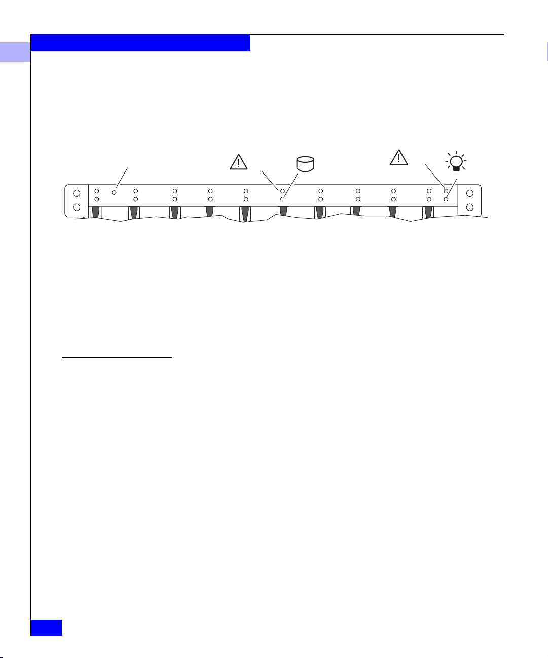
Enclosure address light
(0 for a DPE)
1023 4 5 6 7 8 9
Figure 3-1 Status Lights Visible from the Front of the DPE
Table 3-1 Status Lights Color Codes, Front of DPE
Disk module status lights
(two per module)
Check
Active
DPE status lights
Check
Light Quantity Color Meaning
Enclosure Address 1 Green On to indicate enclosure address zero.
DPE Check 1 Amber On when any fault condition exists; if the fault is not
obvious from another fault light on the front, look at
the back of the DPE.
SP Fan Pack Check 1 Amber On when the SP fan pack is faulty (not visible with
fan pack cover on; to remove cover, see page 3-14).
Power
3-2
EMC Fibre Channel Disk-Array Processor Enclosure (DPE) Hardware Reference
Page 51

Table 3-1 Status Lights Color Codes, Front of DPE (continued)
Light Quantity Color Meaning
Servicing and Upgrading a DPE
3
Disk Active 1 per disk module
slot
Green Off when the module slot is empty or contains a filler
module.
Flashing (mostly off) when the drive is powered up
but not spinning; this is a normal part of the spin-up
sequence, occurring during the spin-up delay of a
slot.
Flashing (at a constant rate) when the disk drive is
spinning up or spinning down normally.
On when the drive is spinning but not handling any
I/O activity (the ready state).
Flashing (mostly on) when the disk drive is spinning
and handling I/O activity.
Disk Check 1 per disk module
slot
Amber On when the disk module is faulty or as an
indication to remove the disk module.
DPE Active 1 Green On when the DPE is powered up.
DPE Check 1 Amber On when any fault condition exists; if the fault is not
obvious from another fault light on the front, look at
the back of the DPE.
SP Fan Pack Check 1 Amber On when the SP fan pack is faulty (not visible with
fan pack cover on; to remove cover, see page 3-14).
Table 3-2 Status Lights Color Codes, Back of DPE
Light Quantity Color Meaning
SP Active 1 per SP Green On when the SP is operating normally
or flashing when firmware is being loaded.
SP Check 1 per SP Amber On when an SP fault condition exists.
LAN Link/Activity 1 per SP Green On when there is a valid Ethernet connection; blinks
during Ethernet activity.
LAN Speed 1 per SP Amber On when the Ethernet connection is a 100Base-TX
connection.
LCC Active 1 per LCC Green On when the LCC is powered up.
LCC Check 1 per LCC Amber On when either the LCC or a FC-AL connection is
faulty.
Power Supply Active 1 per supply Green On when the power supply is operating.
Monitoring DPE Status
3-3
Page 52

Servicing and Upgrading a DPE
3
Table 3-2 Status Lights Color Codes, Back of DPE (continued)
Light Quantity Color Meaning
Power Supply Check 1 per supply Amber On when the power supply is faulty or is not
Cooling Check 1 per supply Amber Flashing when multiple fans in the drive fan pack
Drive Fan Pack Check 1 on fan pack Yellow On when a fan in the drive fan pack is faulty.
Handling CRUs
receiving ac line voltage.
are faulty or the drive fan pack is removed.
The DPE powers down the SPs and disk drives
when the fault persists for more than about two
minutes.
• If the DPE Check light is on, you should look at the other Check
lights to determine which CRU(s) are faulty. If the Check light for
a CRU remains on, replace the CRU as soon as possible.
• If a CRU fails in a DPE that is highly available, the DPE’s high
availability and write cache functionality (if any) will be
compromised until you replace the faulty CRU.
This section describes the precautions that you must take, and the
general procedures you must follow when removing, installing, and
storing CRUs.
Power Issues and CRUs
3-4
EMC Fibre Channel Disk-Array Processor Enclosure (DPE) Hardware Reference
The DPE is designed to be powered up at all times and hot repairable.
Its front door should be closed and each of its compartments should
contain a CRU or filler panel to ensure EMI compliance and proper
air flow over the CRUs.
While the DPE is powered up, you can service or replace any CRU,
although removing an active LCC or SP will affect operating system
access to the LUNs it controls. Do not remove a faulty CRU until you
have a replacement available.
You can remove the drive fan pack or SP fan pack while the DPE is powered
up. If the pack is removed for more than two minutes, the SPs and disk
modules power down. The SPs and disk modules power up when you
reinstall the drive or SP fan pack.
Page 53

Servicing and Upgrading a DPE
Since you can replace or add any CRU without sliding the DPE out of
the cabinet, you do not have to use cabinet anti-tip devices when you
upgrade or service a DPE.
If you need to power down a DPE, either:
• Shut down the main ac lines to the DPE, or
• Remove the drive fan pack (described on page 3-35) and set the
power switch on each power supply to the off (O) position.
3
Handling CRUs
3-5
Page 54

Servicing and Upgrading a DPE
3
Avoiding Electrostatic Discharge (ESD) Damage
When you replace or install CRUs, you can inadvertently damage the
sensitive electronic circuits in the equipment by simply touching
them. Electrostatic charge that has accumulated on your body
discharges through the circuits. If the air in the work area is very dry,
running a humidifier in the work area will help decrease the risk of
ESD damage. You must follow the procedures below to prevent
damage to the equipment.
Read and understand the following instructions.
• Provide enough room to work on the equipment. Clear the work
site of any unnecessary materials or materials that naturally build
up electrostatic charge, such as foam packaging, foam cups,
cellophane wrappers, and similar items.
• Do not remove replacement or upgrade CRUs from their
antistatic packaging until you are ready to install them.
• Gather together the ESD kit and all other materials you will need
before you service a DPE. Once servicing begins, you should
avoid moving away from the work site; otherwise, you may build
up an electrostatic charge.
3-6
• Use the ESD kit when handling any CRU. If an emergency arises
and the ESD kit is not available, follow the procedures in the
“Emergency Procedures (Without an ESD Kit)” section.
• An ESD wristband (part no. 129002319) is supplied with your
DPE. To use it, attach the clip of the ESD wristband (strap) to any
bare (unpainted) metal on the DPE enclosure; then put the
wristband around your wrist with the metal button against your
skin.
Emergency
Procedures (Without
an ESD Kit)
In an emergency when an ESD kit is not available, use the following
procedures to reduce the possibility of an electrostatic discharge by
ensuring that your body and the subassembly are at the same
electrostatic potential.
These procedures are not a substitute for the use of an ESD kit. Follow them
only in the event of an emergency.
EMC Fibre Channel Disk-Array Processor Enclosure (DPE) Hardware Reference
Page 55

Servicing and Upgrading a DPE
• Before touching any CRU, touch a bare (unpainted) metal surface
of the enclosure.
• Before removing any CRU from its antistatic bag, place one hand
firmly on a bare metal surface of the enclosure, and at the same
time, pick up the CRU while it is still sealed in the antistatic bag.
Once you have done this, do not move around the room or contact
other furnishings, personnel, or surfaces until you have installed
the CRU.
• When you remove a CRU from the antistatic bag, avoid touching
any electronic components and circuits on it.
• If you must move around the room or touch other surfaces before
installing a CRU, first place the CRU back in the antistatic bag.
When you are ready again to install the CRU, repeat these
procedures.
Precautions When Removing, Installing, or Storing CRUs
Use the precautions listed below when you remove, handle, or store
CRUs.
3
• Do not remove a faulty CRU until you have a replacement
available.
• Handle a CRU only when using an ESD wristband as follows:
attach the clip of the ESD wristband to the ESD bracket or bare
metal on the DPE enclosure, and put the wristband around your
wrist with the metal button against your skin.
• Handle CRUs gently. A sudden jar, drop, or vibration can
permanently damage a CRU.
• Never use excessive force to remove or install a CRU.
• Store a CRU in the antistatic bag and specially designed shipping
container in which you received it. Use that container if you need
to return the CRU for repair.
• Maintain the location where you store CRUs within the limits
specified in Appendix A.
Precautions When Removing, Installing, or Storing CRUs
3-7
Page 56

Servicing and Upgrading a DPE
3
Precautions When Handling Optical Cables
When working with optical cables, observe the following
precautions:
• Keep the covers on all optical cables and optical GBICs until you
are ready to insert the cables. The covers protect the cables and
connectors, and prevent foreign particles, such as dust, from
entering and affecting the connection.
• Avoid tight bends. If you need to make a 90º bend, do it over 6 to
12 inches
• Do not use optical cables to support weight. That includes long
cable runs without support.
• Do not pull long runs of cable. It is best to lay the cable in place or
pull only a few feet at a time.
• Run the cables so that they are not stepped on or rolled over by
anything.
3-8
EMC Fibre Channel Disk-Array Processor Enclosure (DPE) Hardware Reference
Page 57

Replacing or Adding a Disk Module
Servicing and Upgrading a DPE
3
!
CAUTION
When replacing or adding a disk module, observe the following:
• Remove or install disk modules only while the storage system
is powered up.
• Do not move a disk module that is part of an existing LUN to
another slot in the storage system. If you do, you risk
destroying the storage system beyond recovery, or data loss at
the very least. Each disk module has LUN-identifying
information assigned to it when it is bound. Moving it to
another slot can make the information stored on the disk
module from the original LUN inaccessible. If you must move a
disk module to another slot, unbind the LUN first; unbinding
destroys all data on the LUN.
• A disk module must be inserted all the way or removed
entirely. Do not leave a disk module partially removed except
for periods when you are allowing it to spin down. A disk
module being inserted or removed may be damaged by a
partially removed adjacent module.
• Handle a disk module gently and use an ESD wristband. Do
not remove a faulty disk module until you have a replacement
module (with the same part number) or a filler module
available. The part number (PN005xxxxxx) appears on the top or
bottom of the module. A replacement disk module should have
the same format (52- byte-per-sector format is required for
arrays) and the same capacity (size and speed) as the disk it is
replacing. An add-on can be any capacity but must be the
520-byte-per-sector format. LUNs should be created using disk
modules of equal size and speed.
• When removing or installing multiple disk modules, wait for
the activity lights on all other disk modules to resume a steady
flicker before removing or installing the next disk module. The
activity lights show that the Core Software has rediscovered the
FC loop.
If you want to use a previously used disk module as a spare, contact your
service provider for assistance.
Replacing or Adding a Disk Module
3-9
Page 58

Servicing and Upgrading a DPE
3
You must open the DPE’s front door to access the disk modules. The
door must be closed for EMI compliance when the DPE is powered
up. Open it only to replace or add a disk module.
Removing a Disk or
Disk Filler Module
Latch
Key
To unlock, turn
180o clockwise.
1. Unlock and open the front door as shown below.
A.
If the door is locked:
Insert the key in the door’s latch.
Turn the key 180o clockwise.
Remove the key from the latch, if desired. (If you do not
remove the key, it may fall to the floor after you open the door.)
Latch
B.
Depress the door latch.
C.
Lower the door until it is
perpendicular to the
front of the enclosure.
3-10
CAUTION: Do not force the door open.
If the door snaps off its hinges,
reinstall it by positioning it at a 45
angle to the enclosure, and snapping it
into the hinge openings.
Figure 3-2 Unlocking and Opening the Front Door
EMC Fibre Channel Disk-Array Processor Enclosure (DPE) Hardware Reference
o
Page 59

2. Locate the slot where you want to install the new or replacement
disk module.
3. Remove the disk or disk filler module from the slot as shown
below.
Figure 3-3 Removing a Disk Filler Module
Servicing and Upgrading a DPE
3
Latch
A. Grasp the filler module
handle so your thumb is on
the latch.
B. Push the latch, and pull
the module from its slot.
Figure 3-4 Removing a Disk Module
After removing a disk module, wait for the activity lights on the other
disk modules to resume a steady flicker before removing another disk
module. The activity lights show that the Core Software has rediscovered
the FC loop.
Latch
A.
Check the light.
B.
Grasp the disk module’s handle
so your thumb is on the latch.
C.
If the active light is on steadily, push
the latch, and slowly pull the module
about 3 cm (1 in) from its slot. Wait 30
seconds for the disk to stop spinning.
Then remove the module.
If the active light is off or mostly off,
you do not need to wait for the disk to
stop spinning. Push the latch, and
slowly pull the module from its slot.
Replacing or Adding a Disk Module
3-11
Page 60

Servicing and Upgrading a DPE
3
Continue to the next section to install the new or replacement
disk module.
Installing a Disk
Module
Figure 3-5 Installing a Disk Module
1. Gently insert the module as follows:
Latch
A. Grasp the disk module’s handle.
B. Align the module with the
guides in the slot.
C. Gently push the module into the
slot until the latch engages.
The disk module Active light flashes to reflect the spin-up
sequence (see page 3-2).
After inserting a disk module, wait for the activity lights on the other
drives to resume a steady flicker before inserting another module. The
activity lights show that the Core Software has rediscovered the FC loop.
3-12
2. Remove and store the ESD wristband.
The door must be closed for EMI compliance when the DPE is powered
up. Open it only to replace or add a disk module.
EMC Fibre Channel Disk-Array Processor Enclosure (DPE) Hardware Reference
Page 61

3. Close and lock the front door as shown below.
A. Raise the door until
Servicing and Upgrading a DPE
3
it latches into place.
B. If desired, lock the door as follows:
Insert the key in the door’s latch.
Turn the key 180o counterclockwise.
Remove the key, if desired.
Latch
Latch
Key
To lock, turn key 180o
counterclockwise.
Figure 3-6 Closing and Locking the Front Door
Replacing or Adding a Disk Module
3-13
Page 62

Servicing and Upgrading a DPE
3
Replacing the SP Fan Pack
!
Removing the SP Fan
Pack
CAUTION
Handle a fan pack gently and use an ESD wristband. Do not
remove a faulty fan pack until you have a replacement available.
You can remove the fan pack while the DPE is powered up. If the
pack is removed for more than about two minutes, the SPs and disk
modules power down. The SPs and disk modules power up when
you reinstall the SP fan pack.
1. At the front of the DPE, grasp the SP fan pack cover at its sides
and pull it from its ballstud mounts as shown below.
3-14
Ballstud
Figure 3-7 Removing the SP Fan Pack Cover
2. Remove the fan pack as shown next.
EMC Fibre Channel Disk-Array Processor Enclosure (DPE) Hardware Reference
Page 63

A.
Slide the latches on the fan pack
inward as shown, and hold them in.
Servicing and Upgrading a DPE
B.
Grasp the handles and gently pull
the pack from the enclosure.
3
Figure 3-8 Removing the SP Fan Pack
Installing the SP Fan
Pack
1. At the front of the DPE, insert the replacement fan pack into the
enclosure, and push gently until the latches engage as shown
next.
Replacing the SP Fan Pack
3-15
Page 64

Servicing and Upgrading a DPE
3
LED
Figure 3-9 Installing the Replacement SP Fan Pack
3-16
2. At the front of the deskside DPE, grasp the SP fan pack cover at
its sides and push it onto its ballstud mounts with the louvers
slanted downward as shown next.
EMC Fibre Channel Disk-Array Processor Enclosure (DPE) Hardware Reference
Page 65

Ballstud
Figure 3-10 Installing the SP Fan Pack Cover
Servicing and Upgrading a DPE
3
Replacing an Optical GBIC
!
Removing an Optical
GBIC Connector
CAUTION
Use an ESD wristband.
Before removing any cables, make note of which cables are connected to
which SP ports.
1. Remove any optical cables from the SP, as shown next.
Place the original covers on all optical cables and optical GBIC
connectors while they are disconnected. The covers protect the
cables and connectors and prevent foreign particles, such as dust,
from entering and affecting the connection.
Replacing an Optical GBIC
3-17
Page 66

Servicing and Upgrading a DPE
3
A. Unplug the fibre optic cable
from Port A and/or Port B on
the SP.
B. Install protective covers on
each optical GBIC connector
and on each fibre optic
cable.
Optical GBIC
connector
A
Figure 3-11 Removing an Optical Cable from an SP
Cover
B
Cover
Fibre optic cable
3-18
EMC Fibre Channel Disk-Array Processor Enclosure (DPE) Hardware Reference
Page 67

Servicing and Upgrading a DPE
2. Remove the optical GBIC connector(s) from the SP as shown
below.
B
3
Figure 3-12 Removing an Optical GBIC Connector from an SP
Installing an Optical GBIC Connector
A
While pressing inward on the
retaining clips, pull the optical
GBIC connector out of the SP.
You may need to wiggle the
connector to unseat it.
Retaining clip
Optical GBIC
connector
1. Install the optical GBIC connector(s) on the SP as shown next.
Retaining
clip
Replacing an Optical GBIC
3-19
Page 68

Servicing and Upgrading a DPE
3
A. Position the optical GBIC
connector with the alignment slot
toward the bottom.
B. Push the optical GBIC connector
into SP Port A and/or Port B until
it is firmly seated and the
retaining clips are engaged.
B
A
Alignment slot
Figure 3-13 Installing an Optical GBIC Connector on an SP
Optical GBIC
connector
3-20
EMC Fibre Channel Disk-Array Processor Enclosure (DPE) Hardware Reference
Page 69

Servicing and Upgrading a DPE
2. Install the appropriate optical cable(s) on the SP’s optical GBIC
connector(s) as previously noted and as shown below.
A. Remove the protective covers
on each optical GBIC
connector and on each fibre
optic cable.
B. Plug the fibre optic cable into
Port A and/or Port B on the
SP.
Cover
Optical GBIC
connector
B
Cover
A
3
Figure 3-14 Installing an Optical Cable on an SP
3. Remove and store the ESD wristband.
Removing an SP or an SP Filler Module
!
CAUTION
Handle an SP gently and use an ESD wristband. Do not remove a
faulty SP until you have a replacement module or filler module
available.
SPs, GBICs, and memory modules are separate CRUs. New or
replacement SPs are shipped without memory modules or GBICs.
When a memory module and/or GBICs are ordered with the SP, they
will arrive with the SP; however, they will not be installed on the SP
Fibre optic cable
Removing an SP or an SP Filler Module
3-21
Page 70

Servicing and Upgrading a DPE
3
board. Before you install a new or replacement SP, you must install a
memory module (a new one or one you removed from a returned SP
and saved). When returning a faulty SP, you must remove the
memory modules and optical GBICs before you return the faulty SP.
If you want to install an add-on SP, be sure to install the SP memory
first as shown starting on page 3-25. To add memory to an installed
SP, you must first remove the SP as follows.
Before removing an SP from a storage system that has caching enabled, you
should disable the storage-system cache using a utility described in the
server setup manual.
1. Perform the appropriate substep.
a. If you are removing a filler module, continue to the next step.
b. If you are replacing the SP, remove the cables and GBIC
connectors from the SP (see page 3-17 or page 3-21).
c. If you are removing the SP to replace the memory module,
remove the cables (see page 3-18 or page 3-21).
2. Remove the SP or filler module from its slot as shown next:
3-22
EMC Fibre Channel Disk-Array Processor Enclosure (DPE) Hardware Reference
Page 71

Retaining screw
(one each side)
Servicing and Upgrading a DPE
3
Ejector
(one each side)
A. Loosen the retaining
screws.
B. Simultaneously open the
ejectors as far as they will
go.
C. Gently pull the SP or filler
module from the
enclosure, supporting it at
its sides.
D. If you removed an SP (not
a filler), place it on a
static-free surface.
Figure 3-15 Removing an SP or Filler Module
Removing an SP or an SP Filler Module
3-23
Page 72

Servicing and Upgrading a DPE
3
Installing or Replacing an SP Memory Module
SPs, GBICs, and memory modules are separate CRUs. New or
replacement SPs are shipped without memory modules or GBICs.
When a memory module and/or GBICs are ordered with the SP, they
will arrive with the SP; however, they will not be installed on the SP
board. Before you install a new or replacement SP, you must install a
memory module (a new one or one you removed from a returned SP
and saved). You must remove the memory modules and GBICs
before you return a faulty SP.
Before removing or installing an SP or SP memory module, observe the
following:
• Read "Avoiding Electrostatic Discharge (ESD) damage" on
page 3-6.
• Before removing or installing the SP or SP memory module,
attach the clip of the ESD wristband to the ground on the SP or
DPE enclosure; then put the wristband around your wrist with
the metal button against your skin.
3-24
Removing an SP
Memory Module
1. Remove the SP from the DPE (see page 3-23), and place it on a
static-free work surface.
2. Remove the memory module (DIMM) from the SP as shown next.
EMC Fibre Channel Disk-Array Processor Enclosure (DPE) Hardware Reference
Page 73

Servicing and Upgrading a DPE
3
A. Use your thumbs
to push out on the
locking tabs, and
use your fingers to
lift the DIMM
upward until it
releases from the
tabs.
B. Lift the module out
of the connector,
and place it in its
own antistatic
packaging.
Figure 3-16 Removing the Memory Module from the SP
Locking tabs
Locking tabs
Alignment
notch
Installing an SP
Memory Module
After removing the memory module, if you want to ship the SP, store
it in its antistatic bag and special shipping package. Then remove and
store the ESD wristband.
Depending on the memory size (in megabytes), the SP memory module can
contain chips on only one side or on both sides.
1. Place the SP and the memory module (DIMM) on a static-free
work surface.
2. On the SP, install the DIMM in the appropriate connector as
shown next.
A memory module has a notch on its edge near pin 1 so that you can
insert it only one way. Install memory modules one at a time, and in
order, starting with connector 1 (refer to Figure 3-17).
Installing or Replacing an SP Memory Module
3-25
Page 74

Servicing and Upgrading a DPE
3
A. Lift the module out
of its antistatic
packaging and
place the module
into the connector.
B. Ensure that the
alignment notch is
correctly oriented.
C. Use your fingers
to push out on the
locking tabs, and
use your thumbs
to push the
module in until
seated.
Connector 2
Connector 1
Alignment
notch
Locking tabs
Locking tabs
Connector 4
Connector 3
Figure 3-17 Installing the Memory Module on the SP
3. If you want to install the SP, continue to the next section.
Installing an SP or SP Filler Module
SPs, GBICs, and memory modules are separate CRUs. New or replacement
SPs are shipped without memory modules or GBICs. When a memory
module and/or GBICs are ordered with the SP, they will arrive with the SP;
however, they will not be installed on the SP board. Before you install a new
or replacement SP, you must install a memory module (see page 3-24).
3-26
EMC Fibre Channel Disk-Array Processor Enclosure (DPE) Hardware Reference
Page 75

Installing an SP or SP Filler Module
Servicing and Upgrading a DPE
3
!
CAUTION
Handle an SP gently and use an ESD wristband.
1. Perform this step only if you are installing the DPE into an FC-AL
environment. Otherwise, continue to the next step.
If the DPE is operating in a Fibre Channel Arbitrated Loop
environment, each SP requires a unique FC-AL address ID on the
loop to communicate with a server/host. If you are installing a
replacement SP, set its address to be the same as that of the SP you
removed. If you are installing an add-on SP, set the address to a
unique address on the loop. The FC-AL protocol translates the
address ID into an 8-bit arbitrated loop physical address (ALPA).
Valid Fibre Channel address IDs range from 0 through 125
(decimal), 0 through 7D (hexadecimal).
Using the SP FC-AL ID switches, set the FC-AL address ID, as
shown in Figure 3-18.
Installing an SP or SP Filler Module
3-27
Page 76

Servicing and Upgrading a DPE
3
FC-AL address ID
(decimal)
Left switch
setting
0 0 0
1 0 1
.
.
.
.
.
.
15 0 F
16 1 0
.
.
.
.
.
.
31 1 F
32 2 0
.
.
.
.
.
.
125 7 D
Figure 3-18 Setting the SP Address ID
Right switch
setting
.
.
.
.
.
.
.
.
0
1
2
3
4
5
6
7
8
0
1
F
E
D
C
B
A
2
3
4
5
6
7
9
8
3-28
EMC Fibre Channel Disk-Array Processor Enclosure (DPE) Hardware Reference
Page 77

Servicing and Upgrading a DPE
2. At the back of the deskside DPE, gently insert the SP or filler
module as shown below.
A. Open the ejectors as far as
possible; then gently push
the module into the
enclosure guides,
supporting it at both sides.
B. Close both ejector handles
simultaneously to fully seat
the SP module.
Ejector
(one each side)
3
Figure 3-19 Installing an SP or SP Filler Module
Retaining screw
(one each side)
C. Tighten the retaining
screws.
Installing an SP or SP Filler Module
3-29
Page 78

Servicing and Upgrading a DPE
3
If you just installed an SP filler module, you are done. Remove
and store the ESD wristband. If you just installed a replacement
or add-on SP, continue to the next step.
3. Install or reinstall the GBIC connector(s) and the cables on the SP
(see pages 3-17 and 3-19).
An SP requires an LCC installed in the DPE and in each expansion DAE
on the corresponding loop (for example, SP A requires LCC A, and SP B
requires LCC B). If you install an add-on SP, make sure a second LCC is
installed in the DPE enclosure and in every DAE enclosure on the
corresponding loop.
Replacing or Adding an LCC Module
Removing an LCC
!
CAUTION
Handle an LCC gently and use an ESD wristband. Do not remove a
faulty LCC until you have a replacement or filler module available.
DPEs with two LCCs should have at least one LCC installed while it is
powered up. Try not to remove both LCCs at once.
1. If you are adding a new LCC, remove the LCC filler module as
shown in Figure 3-21; otherwise continue to the next step.
3-30
EMC Fibre Channel Disk-Array Processor Enclosure (DPE) Hardware Reference
Page 79

Latch up
Figure 3-20 Removing an LCC Filler Module
A.
Pull up the latch on
the filler module.
B.
Grasp the filler
module and pull it out
of the enclosure.
Servicing and Upgrading a DPE
3
Proceed to the LCC installation procedure (page 3-32) and install
the new add-on LCC.
2. If required, remove any cable from the LCC expansion (EXP) port
as shown below.
Copper cable
Figure 3-21 Removing a Copper Cable from an LCC
Replacing or Adding an LCC Module
A. Loosen the two screws on
the cable’s connector.
B. Unplug the copper cable
from the LCC connector.
3-31
Page 80

Servicing and Upgrading a DPE
3
3. Remove the LCC from its slot, as shown below.
Latch up
A. Pull up the latch on
the LCC.
Installing an LCC
3-32
EMC Fibre Channel Disk-Array Processor Enclosure (DPE) Hardware Reference
B. Grasp the LCC and gently
pull it out of its slot.
After removing an LCC, wait 6 seconds before inserting it or
another LCC. The wait allows the Core Software to discover that
the LCC has been removed.
Continue to the next section to install the replacement LCC.
!
CAUTION
Handle an LCC gently and use an ESD wristband.
1. Gently insert the LCC as shown in Figure 3-22.
DPE LCCs are not the same as DAE LCCs. Replace a failed LCC with one of
the same type.
Page 81

Servicing and Upgrading a DPE
Latch up
A. Pull up the latch on the LCC.
B. Align the LCC with the guide
on the slot.
C. Gently slide the LCC into the
slot.
D. Push down the latch until
the LCC is fully seated in
the slot.
Latch down
3
Figure 3-22 Installing an LCC Module
The LCC Active light turns on. The activity lights of any affected
disk modules should resume a steady flicker. If the disk activity
lights do not flicker within 6 seconds, remove the LCC and insert
it again.
2. If you are installing a replacement LCC, reattach the copper cable
on the EXP connector, if required, as shown next.
Replacing or Adding an LCC Module
3-33
Page 82

Servicing and Upgrading a DPE
3
A.
Plug the copper cable
into the LCC connector.
B.
Tighten the two screws
on the cable's connector.
Copper cable
Figure 3-23 Reconnecting a Copper Cable to an Expansion LCC
3. You have replaced the LCC. Remove and store the ESD
wristband.
Replacing the Drive Fan Pack
CAUTION
Handle a fan pack gently and use an ESD wristband. Do not
remove a faulty fan pack until you have a replacement unit
available. You can remove the fan pack while the DPE is powered
up. If the pack is removed for more than approximately two
minutes, the SPs and disk modules power down. The SPs and disk
modules will power up when you reinstall the drive fan pack.
3-34
!
EMC Fibre Channel Disk-Array Processor Enclosure (DPE) Hardware Reference
Page 83

Removing the Drive Fan Pack
Servicing and Upgrading a DPE
3
A. Grasp the latches on the drive fan pack.
B. Squeeze the latches together and
gently pull the pack from the enclosure.
Figure 3-24 Removing the Drive Fan Pack
Installing the Drive Fan Pack
As soon as the pack is disconnected from each power supply, the
drive fan pack Check light turns off, if it was not already off; the DPE
Check light on the front panel turns on, if it was not already on; and
the Cooling Check light on each power supply flashes.
You can install the drive fan pack in either horizontal position. For a
consistent image with any DAEs installed above the DPE, we
recommend that you install it with the status light in the upper-right
corner.
Replacing the Drive Fan Pack
3-35
Page 84

Servicing and Upgrading a DPE
3
Check light
A. Grasp the latches on the drive fan pack.
B. Squeeze the latches together and
gently push the pack into the
enclosure until it clicks into place.
Figure 3-25 Installing the Drive Fan Pack
As soon as the pack is in place, the fans start spinning; the DPE Check
light turns off if no other CRUs are faulty; and the Cooling Check
light on each power supply turns off.
Replacing or Adding a Power-Supply Module
CAUTION
To access a power-supply module, you must remove the drive fan
pack. If the drive fan pack is removed for more than two minutes,
the SPs and disk modules power down. The SPs and disk modules
will power up when you reinstall the drive fan pack.
Handle a power supply gently and use an ESD wristband. Do not
remove a power supply until you have a replacement supply or
filler module available.
3-36
!
EMC Fibre Channel Disk-Array Processor Enclosure (DPE) Hardware Reference
Page 85

Servicing and Upgrading a DPE
If one power supply is off and the other is on, do not turn one on and
immediately turn off the other. Instead, turn one on and wait five seconds
before turning the other off.
If you are adding a new power supply, remove the power-supply
filler module as shown next. If you are replacing a faulty power
supply, remove the power-supply module itself as follows.
3
Removing a
Power-Supply Filler
Module
Bottom filler module
A.
Figure 3-26 Removing the Bottom Filler Module
1. Remove the drive fan pack as shown on page 3-35.
2. Remove the filler module as shown in Figures 3-26 and 3-27.
Latch
(one per side)
Push each latch of the filler
module toward the center.
B.
Pull the filler module
from its slot.
Replacing or Adding a Power-Supply Module
3-37
Page 86

Servicing and Upgrading a DPE
3
Top filler module
Latch
(one per side)
A. Push the latches on both sides of the
filler module towards the center.
Figure 3-27 Removing the Top Filler Module
Removing a
Power-Supply Module
!
B. Pull the filler module
from the slot.
3. Install a power supply in the empty slot as explained on
page 3-41.
CAUTION
Turn off the power supply before unplugging the ac line cord from
the supply or removing the supply from the enclosure.
1. Remove the drive fan pack, as shown on page 3-35.
2. Turn off the power supply and unplug its ac line cord as shown
next.
3-38
EMC Fibre Channel Disk-Array Processor Enclosure (DPE) Hardware Reference
Page 87

Servicing and Upgrading a DPE
3
Bottom power supply
Power switch
ac inlet
Channel
ac inlet
ac power cord
(right-angle plug)
For each power supply to be removed:
Power switch
Top power supply
a. Set the power supply’s switch to off (0).
b. Unplug the ac power cord from the supply’s ac inlet.
c. Remove the cord from the enclosure.
Figure 3-28 Turning off a Supply’s Power and Unplugging the AC Line Cord
Replacing or Adding a Power-Supply Module
3-39
Page 88

Servicing and Upgrading a DPE
3
3. Remove the power-supply module, as shown in Figures 3-29 and
3-30.
Latch
A.
With your thumb, push the latch up
and then right as far as possible.
You may need to brace your hand
against the supply module's handle.
B.
Grasp the handle with one hand, and
gently pull the module from the enclosure,
supporting it with your other hand.
3-40
Figure 3-29 Removing the Top Power-Supply Module
EMC Fibre Channel Disk-Array Processor Enclosure (DPE) Hardware Reference
Page 89

Latch
A.
With your thumb, push the latch down,
and then left, as far as possible.
You may need to brace your hand
against the module's handle.
Servicing and Upgrading a DPE
B.
Grasp the handle with one hand, and
gently pull the module from the enclosure,
supporting it with your other hand.
3
Figure 3-30 Removing the Bottom Power-Supply Module
Installing a Power-Supply Module
The top power supply is inverted with respect to the bottom power supply.
Replacing or Adding a Power-Supply Module
3-41
Page 90

Servicing and Upgrading a DPE
3
Slot
Latch
A.
Make sure the module’s latch is
as far left in its slot as possible.
B.
Align the supply with the enclosure slot
and gently push it into the slot until the
latch moves to the middle of the slot.
C.
With your thumb, push the
latch right until it snaps up.
You may need to brace your
hand against the module’s handle.
3-42
Figure 3-31 Installing the Bottom Power Supply
EMC Fibre Channel Disk-Array Processor Enclosure (DPE) Hardware Reference
Page 91

Slot
Servicing and Upgrading a DPE
3
Latch
A. Make sure the module’s latch is as
far right in its slot as possible.
B. Align the module with the slot and
gently push it into the slot until the
latch moves to the middle of the slot.
Figure 3-32 Installing the Top Power Supply
C. With your thumb, push the latch left until it
snaps down.
You may need to brace your hand
against the supply’s handle.
Replacing or Adding a Power-Supply Module
3-43
Page 92

Servicing and Upgrading a DPE
3
4. Plug the ac line cord into the new supply, and turn on its power as
shown below.
5. Reinstall the drive fan pack as shown on page 3-35.
Bottom power supply
Power switch
a. Plug the right-angle plug on the ac line cord into the supply’s ac inlet.
d. Route the cord along the power supply to the side of the enclosure.
The cord must not occupy the space for the drive fan pack.
c. Bend the cord into a U shape and slide the U into the channel so the end of the
cable comes out of the channel at the back of the enclosure.
d. Plug the end of the cord into one of the cabinet’s power outlets.
e. Set the supply’s power switch to the on (1) position.
Channel
ac inlet
ac power cord
(right-angle plug)
For each power supply
ac inlet
Top power supply
Power switch
3-44
Figure 3-33 Plugging in the AC Line Cord and Turning on Power
EMC Fibre Channel Disk-Array Processor Enclosure (DPE) Hardware Reference
Page 93

Invisible Body Tag
This appendix describes the DPE technical specifications, operating
limits, and shipping and storage requirements.
Technical Specifications
Technical specifications include power requirements, size, drive,
interface, and standards information.
A
Technical
Specifications and
Operating Limits
AC Power Requirements
The input current, power (VA), and dissipation per DPE are based on
the maximum capability of the power supplies and cooling system to
provide internal regulated power. Typical values will be less,
depending on the number and manufacturer of disk modules. These
values represent either:
• The values for the line cord of a DPE with a single power supply.
• The total values shared by the line cords of two power supplies in
the same DPE, with the division between the line cords and
supplies at the current sharing ratio.
A failure of one of the two power supplies in the DPE results in the
remaining supply and cord supporting the full load. You must use a
rackmount cabinet with ac power distribution, and have main branch
ac distribution that can handle these values for the DPE and each
DAE in the cabinet.
Technical Specifications and Operating Limits
A-1
Page 94

A
Technical Specifications and Operating Limits
Requirement Description
ac line voltage 100 to 240 Vac +10%, single phase, 47 to 63 Hz
ac line current 8.0 A max estimate at 100 V (fully configured)
Power consumption 800 VA max estimate (fully configured)
Power dissipation 792 W max estimate (fully configured)
Power factor 0.99 min at full load, low voltage
Heat dissipation 2851x10
In-rush current 50 A max estimate for 1/2 line cycle, per power supply
ac protection 12 A thermal circuit breaker on each power supply
ac inlet type IEC320-C14 appliance coupler
Hold-up time 10 ms min at 50 Hz
Current sharing 60% max, 40% min
3
J/hr (2703 BTU/hr) max estimate
Size and Weight
A-2
EMC Fibre Channel Disk-Array Processor Enclosure (DPE) Hardware Reference
Item Measurement
Height 28.59 cm (11.25 in), 6.5 NEMA units (U), including mounting hardware
Width 44.5 cm (17.5 in); mounting bars fit standard 19-inch NEMA cabinets
Depth 70.02 cm (27.57 in) front door to back of drive fan pack
67.10 cm (26.42 in) enclosure front to back of drive fan pack
64.12 cm (25.24 in) rail front to back of drive fan pack
Weight DPE with 2 SPs, 2 LCCs, 2 power supplies, and 10 disk
modules: 52.0 kg (114.4 lbs)
Disk module: 1.0 kg (2.3 lbs)
Drive fan pack: 1.8 kg (4.0 lbs)
SP: 1.8 kg (4.0 lbs)
SP fan pack: 1.8 kg (4.0 lbs)
LCC (link control card): 0.8 kg (1.7 lbs)
Power supply: 5.4 kg (12.0 lbs)
Page 95

Technical Specifications and Operating Limits
A
Drive Type
SP Optical Cabling
LCC Copper Cabling
3.5-inch drives, Fibre Channel interface, 2.54 cm (1.0-inches) or 4.06
cm (1.6-inches) tall.
The SP optical cable interface to the external Fibre Channel
environment is as follows:
Type 50 µm or 62.5 µm, multi-mode, dual SC
Length 50 µm: 2 m (6.6 ft) minimum to 500 m (1,650 ft) maximum 62.5 µm: 2
m (6.6 ft) min to 300 m (985 ft) maximum
Bend radius 3 cm (1.2 in) minimum
The DPE’s LCC expansion port interface to the DAE is copper cable
as follows:
Type Shielded, 150Ω differential, shield bonded to DB-9 plug connector
shell (360×)
FC-AL Standard, Revision 4.4 or higher
Length 0.3 m (1 ft) min, 10 m (33 ft) max unequalized between DPE and
DAEs
Standards Certification and Compliance
A stand-alone DPE will be tested and certified for compliance with
the international environmental and safety specifications listed next.
Each DPE will be marked to indicate such compliance and
certification as required.
Technical Specifications
A-3
Page 96

A
Technical Specifications and Operating Limits
Safety Standards
Standard Description
EMI Standards
CSA 22.2 No. 950 Safety of Information Technology Equipment including Electrical
Business Equipment
UL 1950 Safety of Information Technology Equipment including Electrical
Business Equipment
CE Mark European EMC Directive & Low Voltage Directive
Requirements. Including: EN 60950 - Safety of Information
Technology Equipment including Electrical Business Equipment,
TUV-GS, and CB REPORT
Standard Description
FCC Part 15 Class A, Radio Frequency Device Requirements
ICES-003 Class A, Interference-Causing Equipments Standard - Digital
Apparatus
CE Mark European EMC Directive & Low Voltage Directive
Requirements. Including: CISPR22 - Class A, Limits & Methods
of Measurement of Radio Interference Characteristics of ITE
and EN55022- Class A.
VCCI Class A, Voluntary Control Council for Interference
AS/NZS 3548 Class A, Electromagnetic Interference - Limits & Methods of
Measurement of ITE
Fibre Channel Related
A-4
EMC Fibre Channel Disk-Array Processor Enclosure (DPE) Hardware Reference
CNS13438 BSMI EMC Requirements
Standards
Standard Description
Fibre Channel Physical and signaling interface, FC-PH, Revision 4.4
Fibre Channel Arbitrated Loop (FC-AL), Revision 4.5
Fibre Channel Private Loop Direct Attach (PLDA), Revision 1.10
SCSI III SCSI Enclosure Services (SES), Revision 8a
Page 97

Operating Limits
Technical Specifications and Operating Limits
A
The ambient temperature specification is measured at the front door
inlet. The site must have air conditioning of the correct size and
placement to maintain the specified ambient temperature range. The
air conditioning must be able to handle the BTU requirements of the
DPEs.
Requirement Description
Ambient temperature 10°C to 40°C (50°F to 104°F)
Temperature gradient 10°C/hr (50°F/hr)
Relative humidity 20% to 80% noncondensing
Elevation 2438 m (8,000 ft) at 40°C; 3077 m (10,000 ft) at 37°C
Drive module power 25 W drive slot maximum (seeking)
The operating limits listed above for temperature and humidity must not be
exceeded inside the closed cabinet in which the DPE and any DAEs are
mounted. Mounting equipment in a cabinet directly above or below a DPE
does not restrict air flow to the DPE because air flows through the DPE from
front to back. Cabinet doors must not impede the front-to-back air flow.
Operating Limits
A-5
Page 98

A
Technical Specifications and Operating Limits
Shipping and Storage Requirements
Requirement Description
Ambient temperature -40°C to 65°C (-40°F to 149°F)
Temperature gradient 25°C/hr (77°F/hr)
Relative humidity 10% to 90% noncondensing
Elevation 7625 m (25,000 ft.)
A-6
EMC Fibre Channel Disk-Array Processor Enclosure (DPE) Hardware Reference
Page 99

Glossary
The terms defined here are important to installing and maintaining a
storage system.
A
ALPA (arbitrated loop
physical address)
bind In the context of a disk-array storage system, the procedure by
BTU (British Thermal
Unit)
cache See storage-system caching.
CRU (customer-
replaceable unit)
DAE (Disk Array
Enclosure)
An 8-bit address that uniquely identifies an SP (or other device)
on an FC-AL loop.
which you hardware-format one or more disk modules into one
LUN (logical unit) — usually as one several types of RAID group.
B
A standard measure of a device’s heat output.
C
A hardware component, such as a disk module, that anyone can
install or replace.
D
A storage device that includes an enclosure, up to 10 disk
modules, one or two Fibre Channel LCCs, and one or two power
supplies.
EMC Fibre Channel Disk-Array Processor Enclosure (DPE) Hardware Reference
g-1
Page 100

Glossary
DPE (Disk-Array
Processor
Enclosure)
DIMM (dual in-line
memory module)
disk-drive module Another name for disk module.
disk module A self-contained disk drive that slides into one of the slots in the
disk unit A short name for physical disk unit.
A storage device that includes an enclosure, up to 10 disk
modules, one or two SPs, one or two Fibre Channel LCCs, and
one or two power supplies. A DPE can support up to 11 DAEs
(each with up to 10 disk modules) in addition to its own 10 disk
modules, for a total of 120 disk modules. You can attach a DPE to
one or more servers or external hubs in any of many different
configurations.
A type of memory module used for SP memory.
front of the enclosure. The carrier assembly holds the disk drive.
E
EA (enclosure
address)
A number, selectable on a DAE front panel, fixed at 0 on a DPE,
that helps establish a unique address for each disk module on an
FC-AL loop. You must set the EA on each DAE. Since the DPE EA
is 0, you might set the first DAE EA to 1, the second to 2, and so
on up to a total of 12 enclosures.
EMI (electromagnetic
interference)
ESD (electrostatic
FC-AL (Fibre Channel
Arbitrated Loop)
FC-AL address ID A number that identifies a device as a node on a Fibre Channel
g-2
EMC Fibre Channel Disk-Array Processor Enclosure (DPE) Hardware Reference
discharge)
Electronic radiation emitted by an electrical device. The levels of
EMI are strictly controlled for data processing equipment. The
EMI standards are explained after the Notice page near the
beginning of the manual.
The discharge of an accumulated electrical charge (static). This
can severely damage delicate electronic circuits and you should
take steps to prevent this, as explained in Chapter 3.
F
An arrangement of Fibre Channel stations such that messages
pass from one to the next in a ring.
loop. You select the FC-AL address ID for an SP using switches
on the back of the storage system. The default FC-AL address ID
for SP A is 0; the default FC-AL address ID for SP B is 1.
 Loading...