

Page 1

EMC Enterprise Storage
EMC Disk-Array Processor Enclosure (DPE)
Deskside Model FC4400/4500
HARDWARE REFERENCE
P/N 014002902-02
EMC Corporation 171 South Street, Hopkinton, MA 01748-9103
Corporate Headquarters: (508) 435-1000, (800) 424-EMC2 Fax: (508) 435-5374 Service: (800) SVC-4EMC
Page 2

Copyright © EMC Corporation 2000. All rights reserved.
Printed December 2000
No part of this publication may be reproduced or distributed in any form or by any means, or stored in a
database or retrieval system, without the prior written consent of EMC Corporation.
The information contained in this document is subject to change without notice. EMC Corporation assumes
no responsibility for any errors that may appear.
All computer software programs, including but not limited to microcode, described in this document are
furnished under a license, and may be used or copied only in accordance with the terms of such license.
EMC either owns or has the right to license the computer software programs described in this document.
EMC Corporation retains all rights, title and interest in the computer software programs.
EMC Corporation makes no warranties, expressed or implied, by operation of law or otherwise, relating to
this document, the products or the computer software programs described herein. EMC CORPORATION
DISCLAIMS ALL IMPLIED WARRANTIES OF MERCHANTIBILITY AND FITNESS FOR A PARTICULAR
PURPOSE. In no event shall EMC Corporation be liable for (a) incidental, indirect, special, or consequential
damages or (b) any damages whatsoever resulting from the loss of use, data or profits, arising out of this
document, even if advised of the possibility of such damages.
Trademark Information
EMC2 and Navisphere are registered trademarks and Access Logix is a trademark of EMC Corporation.
All other trademarks used herein are the property of their respective owners.
ii
EMC Disk-Array Processor Enclosure (DPE) Deskside Model FC4400/4500 Hardware Reference
Page 3

Contents
Preface..............................................................................................................................xi
Chapter 1 About the Deskside Disk-Array Processor Enclosure
Overview............................................................................................1-2
Deskside DPE Components.............................................................1-3
Front Doors.................................................................................1-4
Enclosures ..........................................................................................1-5
Disk Modules .............................................................................1-8
Disk Drives .................................................................................1-8
Link Control Cards (LCCs).......................................................1-9
Storage Processors (SPs) .........................................................1-11
Power Supplies................................................................................1-13
Drive Fan Pack ................................................................................1-15
SP Fan Pack...............................................................................1-16
Standby Power Supply (SPS).................................................1-17
Power Distribution Units (PDUs)..........................................1-18
Redundancy in Configurations.....................................................1-19
EMI Compliance .............................................................................1-24
What Next? ......................................................................................1-25
Chapter 2 Installing a Deskside DPE
Requirements.....................................................................................2-2
Site Requirements......................................................................2-2
Addressing Requirements........................................................2-3
Installing a Deskside DPE................................................................2-4
Deskside DPE Powerup and Initialization Sequence................2-15
DPE Powerdown.............................................................................2-16
Turning Off Power Correctly .................................................2-16
EMC Disk-Array Processor Enclosure (DPE) Deskside Model FC4400/4500 Hardware Reference
iii
Page 4

Contents
Turning On Power...................................................................2-17
Binding Disk Modules Into RAID Groups..................................2-18
Chapter 3 Servicing and Upgrading a Deskside DPE
Monitoring System Status ...............................................................3-2
Handling CRUs.................................................................................3-7
Power Issues and CRUs............................................................3-7
Avoiding Electrostatic Discharge (ESD) Damage .................3-7
Emergency Procedures (Without an ESD Kit).......................3-8
Precautions When Removing, Installing, or Storing CRUs.3-9
Precautions When Handling Optical Cables ..............................3-10
Replacing or Adding a Disk Module...........................................3-11
Removing a Disk or Disk Filler Module ..............................3-12
Installing a Disk Module........................................................3-14
Replacing the SP Fan Pack ............................................................3-16
Removing the SP Fan Pack.....................................................3-16
Installing the SP Fan Pack......................................................3-17
Replacing an Optical GBIC............................................................3-19
Removing an Optical GBIC Connector ................................3-19
Installing an Optical GBIC Connector..................................3-22
Replacing a Copper GBIC..............................................................3-24
Installing a Copper GBIC Connector....................................3-25
Removing an SP or an SP Filler Module .....................................3-28
Installing or Replacing an SP Memory Module.........................3-30
Removing an SP Memory Module........................................3-30
Installing an SP or SP Filler Module ............................................3-33
Replacing or Adding an LCC Module.........................................3-36
Removing Copper Cable(s) from an LCC............................3-37
Installing an LCC.....................................................................3-39
Replacing the Drive Fan Pack.......................................................3-42
Removing a Drive Fan Pack...................................................3-43
Installing the Drive Fan Pack.................................................3-44
Replacing or Adding a Power Supply Module..........................3-45
Removing a Power-Supply Filler Module ...........................3-45
Removing a Power Supply.....................................................3-46
Installing a Power Supply......................................................3-50
Appendix A Specifications and Operational Requirements
Technical Specifications .................................................................A-2
AC Power Requirements.........................................................A-2
Requirements for the DPE Enclosure....................................A-2
For the DAE Enclosure ............................................................A-3
iv
EMC Disk-Array Processor Enclosure (DPE) Deskside Model FC4400/4500 Hardware Reference
Page 5

Contents
Size and Weight........................................................................A-3
Service Clearance .....................................................................A-4
Drive Type................................................................................. A-4
LCC FC-AL interface .............................................................. A-4
SP Optical Cabling................................................................... A-4
LCC Copper Cabling...............................................................A-5
Standards Certification and Compliance ....................................A-6
Safety Standards.......................................................................A-6
EMI Standards..........................................................................A-6
Fibre Channel Related Standards.......................................... A-6
Operating Limits ............................................................................A-7
Shipping and Storage Requirements ...........................................A-8
Glossary.........................................................................................................................g-1
Index ................................................................................................................................i-1
EMC Disk-Array Processor Enclosure (DPE) Deskside Model FC4400/4500 Hardware Reference
v
Page 6

Contents
vi
EMC Disk-Array Processor Enclosure (DPE) Deskside Model FC4400/4500 Hardware Reference
Page 7

Figures
1-1 Deskside Disk-Array Processor Enclosure (DPE) .................................... 1-2
1-2 Front View Showing Doors and Disk Module IDs .................................. 1-4
1-3 DPE Front Panel ............................................................................................ 1-6
1-4 DAE Front Panel ........................................................................................... 1-7
1-5 Disk Module .................................................................................................. 1-8
1-6 Types of LCC ................................................................................................. 1-9
1-7 LCC Ports and Indicators .......................................................................... 1-10
1-8 SP Back Panel .............................................................................................. 1-11
1-9 Installing an SP ........................................................................................... 1-12
1-10 Power Supply Controls and Indicators ................................................... 1-13
1-11 Drive Fan Pack ............................................................................................ 1-15
1-12 SP Fan Pack ................................................................................................. 1-17
1-13 SPS ................................................................................................................ 1-17
1-14 PDU .............................................................................................................. 1-18
1-15 Disk Modules in a Deskside DPE ............................................................. 1-19
1-16 Back View Showing Components ............................................................ 1-20
1-17 High Availability Configuration, No Write Caching, Back View
with Cables and Drive Fan Packs Removed ............................................ 1-21
1-18 High Availability Configuration, Minimum Write Caching, Back View
with Cables and Drive Fan Packs Removed ............................................ 1-22
1-19 High Availability Configuration, Write Caching High Availability,
Back View with Cables and Drive Fan Packs Removed ........................ 1-23
1-20 Compliance Label Locations ..................................................................... 1-24
2-1 Locking and Unlocking the Front Wheels ................................................ 2-4
2-2 Turning Power Off ....................................................................................... 2-5
2-3 Unlocking and Opening the Front Door ................................................... 2-5
2-4 Setting the Enclosure Address (EA) .......................................................... 2-6
2-5 Closing and Locking the Front Door ......................................................... 2-7
2-6 Storage Processor FC-AL ID Switches ....................................................... 2-8
2-7 Connecting the Power Cord ........................................................................ 2-9
EMC Disk-Array Processor Enclosure (DPE) Deskside Model FC4400/4500 Hardware Reference
vii
Page 8

Figures
2-8 Attaching Optical Cables to a DPE ........................................................... 2-10
2-9 Attaching Copper Cables to a DPE .......................................................... 2-11
2-10 Cabling a DPE to a DAE ............................................................................. 2-12
2-11 Daisy-Chaining a 10-slot Deskside DAE from a Deskside DPE
with Copper Cable ...................................................................................... 2-13
2-12 Turning Power On ...................................................................................... 2-14
2-13 Powering Down .......................................................................................... 2-16
3-1 DPE Front Panel ............................................................................................ 3-2
3-2 DAE Front Panel ........................................................................................... 3-5
3-3 Unlocking and Opening the Front Door .................................................. 3-12
3-4 Removing a Disk Filler Module ................................................................ 3-13
3-5 Removing a Disk Module .......................................................................... 3-13
3-6 Installing a Disk Module ............................................................................ 3-14
3-7 Closing and Locking the Front Door ........................................................ 3-15
3-8 Removing the SP Fan Pack Cover ............................................................ 3-16
3-9 Removing an SP Fan Pack ......................................................................... 3-17
3-10 Installing the Replacement SP Fan Pack .................................................. 3-17
3-11 Installing the SP Fan Pack Cover .............................................................. 3-18
3-12 Removing an Optical Cable from an SP .................................................. 3-20
3-13 Removing an Optical GBIC Connector from an SP ............................... 3-21
3-14 Installing an Optical GBIC Connector on an SP ..................................... 3-22
3-15 Installing an Optical Cable on the SP Optical GBIC Connector ........... 3-23
3-16 Removing a Copper Cable from an SP .................................................... 3-24
3-17 Removing a Copper GBIC Connector from an SP ................................. 3-25
3-18 Installing a Copper GBIC Connector on an SP ....................................... 3-26
3-19 Installing a Copper Cable on the SP Copper GBIC Connector ............ 3-27
3-20 Removing an SP or Filler Module ............................................................. 3-29
3-21 Removing the Memory Module from the SP .......................................... 3-31
3-22 Installing the Memory Module on the SP ................................................ 3-32
3-23 Setting the SP Address ID .......................................................................... 3-34
3-24 Installing an SP or SP Filler Module ......................................................... 3-35
3-25 Removing an LCC Filler Module .............................................................. 3-36
3-26 Removing Copper Cables .......................................................................... 3-37
3-27 Removing the LCC ...................................................................................... 3-38
3-28 Installing an LCC ........................................................................................ 3-39
3-29 Connecting or Reconnecting Copper Cable(s) to an LCC ..................... 3-40
3-30 Connecting a 10-Slot Deskside DAE to a Deskside DPE with
Copper Cable ............................................................................................... 3-41
3-31 Removing a Drive Fan Pack ...................................................................... 3-43
3-32 Installing a Drive Fan Pack ........................................................................ 3-44
3-33 Removing a Power-Supply Filler Module ............................................... 3-46
3-34 Turning Off the Power Supply .................................................................. 3-47
viii
EMC Disk-Array Processor Enclosure (DPE) Deskside Model FC4400/4500 Hardware Reference
Page 9

3-35 For Power Supplies Installed with the Power Switch
at the Bottom ................................................................................................ 3-48
3-36 For Power Supplies Installed with the Power Switch
at the Top ...................................................................................................... 3-49
3-37 For Power Supplies Installed with the Power Switch
at the Bottom ............................................................................................... 3-50
3-38 For Power Supplies Installed with the Power Switch
at the Top....................................................................................................... 3-51
3-39 Turning on the Power Supply .................................................................. 3-52
Figures
EMC Disk-Array Processor Enclosure (DPE) Deskside Model FC4400/4500 Hardware Reference
ix
Page 10

Figures
x
EMC Disk-Array Processor Enclosure (DPE) Deskside Model FC4400/4500 Hardware Reference
Page 11

Tables
3-1 Status Lights Visible on the DPE Front Panel .......................................... 3-3
3-2 Status Light Visible on the SP Fan Module .............................................. 3-3
3-3 Status Lights Visible from the Back of the Deskside DPE ...................... 3-3
3-4 Status Lights Visible on the DAE Front Panel .......................................... 3-6
EMC Disk-Array Processor Enclosure (DPE) Deskside Model FC4400/4500 Hardware Reference
xi
Page 12

Tab les
xii
EMC Disk-Array Processor Enclosure (DPE) Deskside Model FC4400/4500 Hardware Reference
Page 13

Preface
This manual explains how to install the EMC FC4400/4500 deskside
Disk-Array Processor Enclosure (DPE) and how to replace and add
customer-replaceable units (CRUs).
The document is written for service personnel. If you will install and
service the deskside DPE, you should read this manual. After reading
it, you will be able to install a deskside DPE, replace any CRUs that
may fail, and upgrade a deskside DPE by adding disk modules and
redundant CRUs.
How This Manual is
Organized
Related
Documentation
EMC Disk-Array Processor Enclosure (DPE) Deskside Model FC4400/4500 Hardware Reference
Chapter 1 Introduces the deskside DPE’s components.
Chapter 2 Explains requirements and describes how to
install the deskside DPE and cable it to the
server and to other deskside Disk Array
Enclosures (DAEs).
Chapter 3 Describes how to replace CRUs such as disk
modules.
Appendix A Lists the deskside DPE’s technical
specifications.
Glossary Defines terms used in the Fibre Channel
environment.
• EMC Fibre Channel Disk Array Enclosure (DAE) Deskside
Model Hardware Reference, P/N 014002631
• EMC Fibre Channel DC Standby Power Supply (SPS)
Installation Guide, P/N 014002887
xiii
Page 14
Preface
Conventions Used in
this Manual
!
EMC uses the following conventions for notes, cautions, warnings,
and danger notices.
A note presents information that is important, but not hazard-related.
CAUTION
A caution contains information essential to avoid damage to the
system or equipment. The caution may apply to hardware or
software.
WARNING
A warning contains information essential to avoid a hazard that can
cause severe personal injury, death, or substantial property damage
if you ignore the warning.
DANGER
A danger notice contains information essential to avoid a hazard
that will cause severe personal injury, death, or substantial property
damage if you ignore the warning.
EMC uses the following type style conventions in this guide:
Boldface • Specific filenames or complete paths.
• Dialog box names and menu items in text.
• Selections you can make from the user
interface, including buttons, icons, options,
and field names.
• Emphasis in cautions and warnings.
Italic • New terms or unique word usage in text.
• Command line arguments when used in text.
Fixed space Examples of specific command entries that you
would type, displayed text, or program listings.
For example:
xiv
QUERY [CUU=cuu|VOLSER=volser]
Fixed italic Arguments used in examples of command line
syntax.
EMC Disk-Array Processor Enclosure (DPE) Deskside Model FC4400/4500 Hardware Reference
Page 15

Where to Get Help Obtain technical support by calling your local sales office.
If you are located outside the USA, call the nearest EMC office for
technical assistance. These offices are listed at the back of this
manual.
For service, call the appropriate number, and ask for Customer
Service.
United States: (800) 782-4362 (SVC-4EMC)
Canada: (800) 543-4782 (543-4SVC)
Worldwide: (508) 497-7901
Your Comments Your suggestions will help us continue to improve the accuracy,
organization, and overall quality of the user publications. Please
e-mail us at techpub_comments@emc.com to let us know your
opinion or any errors concerning this manual.
Preface
EMC Disk-Array Processor Enclosure (DPE) Deskside Model FC4400/4500 Hardware Reference
xv
Page 16

Preface
xvi
EMC Disk-Array Processor Enclosure (DPE) Deskside Model FC4400/4500 Hardware Reference
Page 17

1
About the Deskside
Disk-Array Processor
Enclosure
This chapter discusses the EMC FC4400/4500 deskside Disk-Array
Processor Enclosure (DPE). Major topics include:
• Overview.............................................................................................1-2
• Deskside DPE Components..............................................................1-3
• Enclosures ...........................................................................................1-5
• Power Supplies.................................................................................1-13
• Drive Fan Pack..................................................................................1-15
• Redundancy in Configurations......................................................1-19
• EMI Compliance...............................................................................1-24
About the Deskside Disk-Array Processor Enclosure
1-1
Page 18
About the Deskside Disk-Array Processor Enclosure
1
Overview
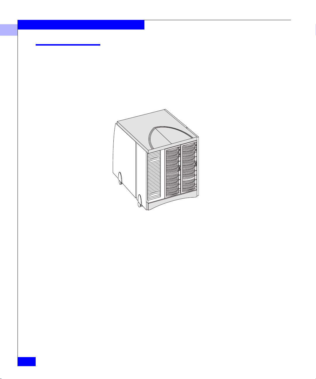
The EMC FC4400/4500 deskside Disk-Array Processor Enclosure
(DPE) consists of one DPE and one Disk-Array Enclosure (DAE). The
deskside DPE is a highly available, high-performance, high-capacity
disk-array storage system that uses a Fibre Channel arbitrated loop
(FC-AL) or fabric as its interconnect interface. Its modular design
makes expansion easy when storage needs increase.
1-2
Figure 1-1 Deskside Disk-Array Processor Enclosure (DPE)
A deskside DPE can support as many as twenty 3.5-inch, Fibre
Channel disk modules. It connects to the external Fibre Channel
environment using GigaBit Interface Converters (GBICs) on the
storage processor.
High-availability features are standard.The EMC Access Logix™
option provides Storage Group functionality for the Model FC4500
DPE.
EMC Disk-Array Processor Enclosure (DPE) Deskside Model FC4400/4500 Hardware Reference
Page 19

Deskside DPE Components
The components of a deskside DPE include:
• Front doors (two)
• Enclosures (DPE and DAE)
• Disk modules
• Link control cards (LCCs)
• Storage processors (SPs)
• Power supplies
• Fan packs (drive and SP)
• Standby Power Supply (SPS)
• Power Distribution Units (PDUs)
Any unoccupied slot (SP, LCC, disk module, or power supply) has a
filler module to maintain air flow and compliance with
electromagnetic interference (EMI) standards.
About the Deskside Disk-Array Processor Enclosure
1
The disk modules, link control cards, power supplies, storage
processors, SPSs, and fan packs are customer-replaceable units (CRUs),
which you can add or replace without any tools while the deskside
DPE is powered up.
The high availability features for a deskside DPE include:
• Second SP, power supply, and LCC (in the DPE enclosure)
• Second LCC and power supply (in the DAE enclosure)
• SPS (See “Related Documentation” on page xiii.)
A second SP (with required second LCC in the DPE enclosure)
provides continued access to the DPE and any connected DAEs if the
first SP or LCC fails. The second SP can improve performance and
connect easily to a second server.
The FC-AL compliant disk drives support dual-port Fibre Channel
connections through the link control cards and the associated cabling.
Simple serial cabling provides easy scalability, allowing you to
configure a single disk-array system using a deskside DPE and
add-on DAEs.
Deskside DPE Components
1-3
Page 20
About the Deskside Disk-Array Processor Enclosure
1
Front Doors
Each front door has a locking latch and an electromagnetic
interference (EMI) shield. The latch is a push button with a removable
locking key that you can use in any deskside DPE or deskside DAE.
When the door is open, you can remove and install drive modules,
and change the DAE enclosure address (EA) using the EA switch.
The front door must be closed for the deskside DPE to be EMI compliant.
Open the door only to access the disk modules or the EA switch for service.
10
0
1
2
3
4
5
6
7
8
9
11
12
13
14
15
16
17
18
19
DAE door latch
1-4
DAE door
DPE door latch
Disk module ID
Figure 1-2 Front View Showing Doors and Disk Module IDs
EMC Disk-Array Processor Enclosure (DPE) Deskside Model FC4400/4500 Hardware Reference
DPE door
Page 21

Enclosures
About the Deskside Disk-Array Processor Enclosure
1
The deskside DPE includes two enclosures, a DPE and a DAE. The
DPE enclosure consists of a sheet-metal housing with a front panel, a
midplane, and slots for up to ten disk modules, link control cards,
power supplies, storage processors, a storage processor fan pack, and
a drive fan pack. The DAE enclosure consists of a sheet-metal
housing with a front panel, a midplane, and slots for up to ten disk
modules, link control cards, power supplies and a drive fan pack. The
enclosures are surrounded by plastic covers.
Enclosures
1-5
Page 22

About the Deskside Disk-Array Processor Enclosure
1
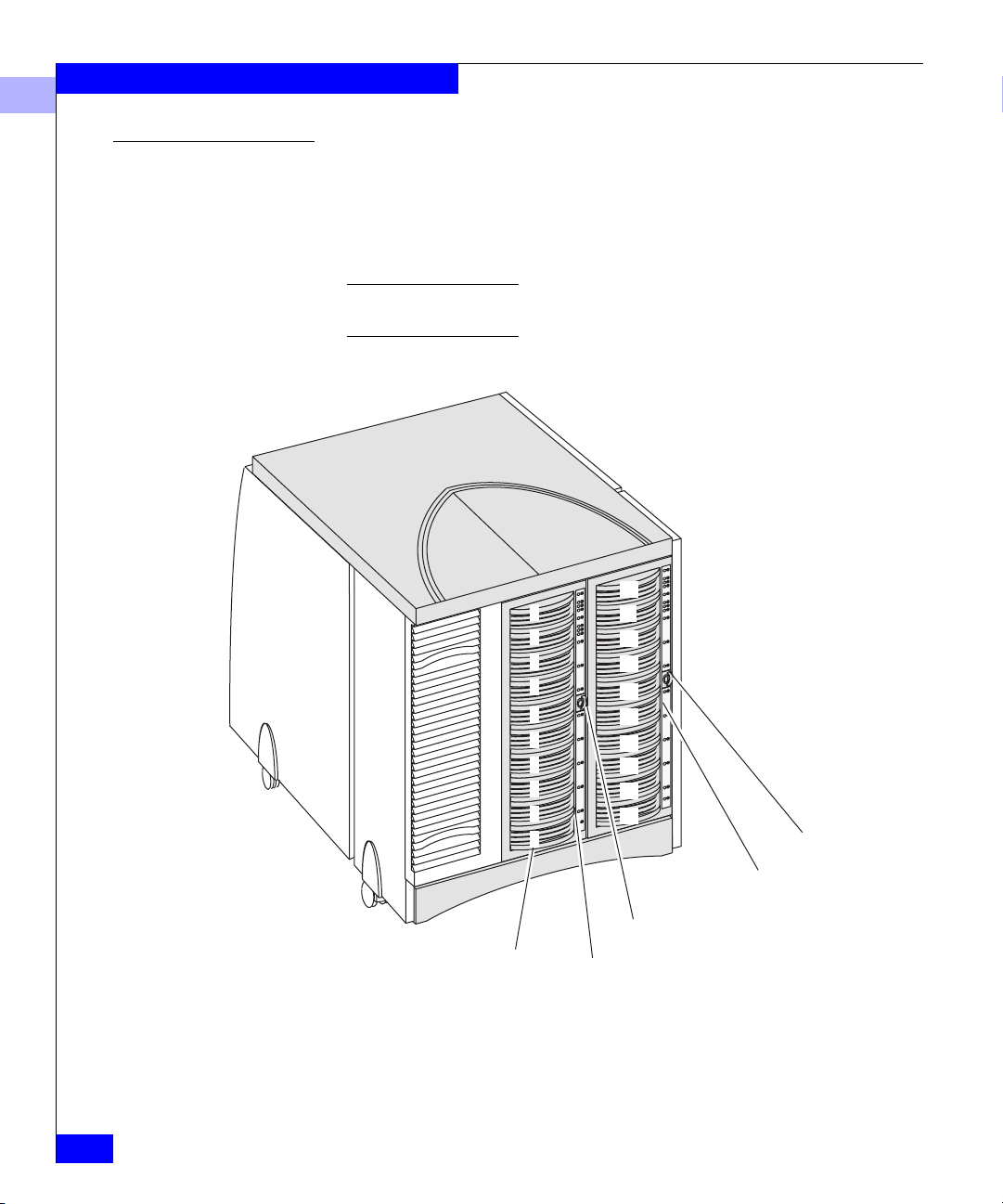
Enclosure address lights
Enclosure address switch
(not visible with front door
closed)
Disk Check
Disk module status lights
(two per module)
1-6
Disk Active
System Check
DAE status lights
Power
Figure 1-3 DPE Front Panel
EMC Disk-Array Processor Enclosure (DPE) Deskside Model FC4400/4500 Hardware Reference
Page 23
About the Deskside Disk-Array Processor Enclosure
The DPE front panel contains DPE status lights, disk module status
lights, and an enclosure address (EA) light. The status lights are all
visible when the front door is closed. The DPE and disk module
status lights are described in the “Monitoring System Status” section
of Chapter 3.
0
1
1
2
3
4
Enclosure address light
Disk Check
5
6
7
8
9
Disk module status lights (two
per module)
Disk Active
System Check
Figure 1-4 DAE Front Panel
DPE status lights
Power
Enclosures
1-7
Page 24
About the Deskside Disk-Array Processor Enclosure
1
The DAE front panel contains DAE status lights, disk module status
lights, enclosure address (EA) lights, and an EA switch. The status
lights are all visible when the front door is closed.
The DAE and disk module status lights are described in the
“Monitoring System Status” section of Chapter 3.
Midplane The midplane distributes power and signals to all components in an
enclosure. All CRUs except the fan packs plug directly into the
midplane connectors.
Disk Modules
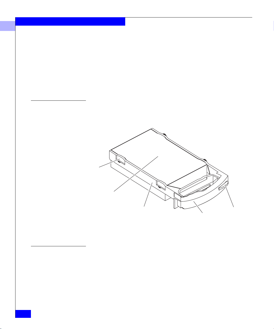
Disk Drives
Each disk module (see figure below) consists of one Fibre Channel
disk drive in a carrier. You can add or remove a disk module while
the deskside DPE is powered up.
Shock
mounts
(4)
Disk drive
Figure 1-5 Disk Module
The disk drives are 3.5-inch Fibre Channel drives and conform to the
following standards:
Carrier
Latch
Handle
1-8
• SFF-8067
• FC-AL
• FC-AL Private Loop Direct Attach (PLDA) profile
EMC Disk-Array Processor Enclosure (DPE) Deskside Model FC4400/4500 Hardware Reference
Page 25
About the Deskside Disk-Array Processor Enclosure
The disk module slots in the enclosure accommodate drives with
heights of either 2.54 cm (1.0 inch) or 4.06 cm (1.6 inches). You can
combine drives of either height, and from different manufacturers,
within the same deskside DPE, subject to the restrictions imposed by
the Licensed Internal Code (LIC) running in the DPE’s SPs.
Drive Carrier The disk drive carrier is a plastic assembly that provides smooth,
reliable contact with the enclosure slot guides and the midplane
connectors. It has a handle with a latch and electrostatic discharge
(ESD) clips, which connect to the drive’s head-disk assembly. The
latch holds the disk module in place to ensure proper connection with
the midplane.
1
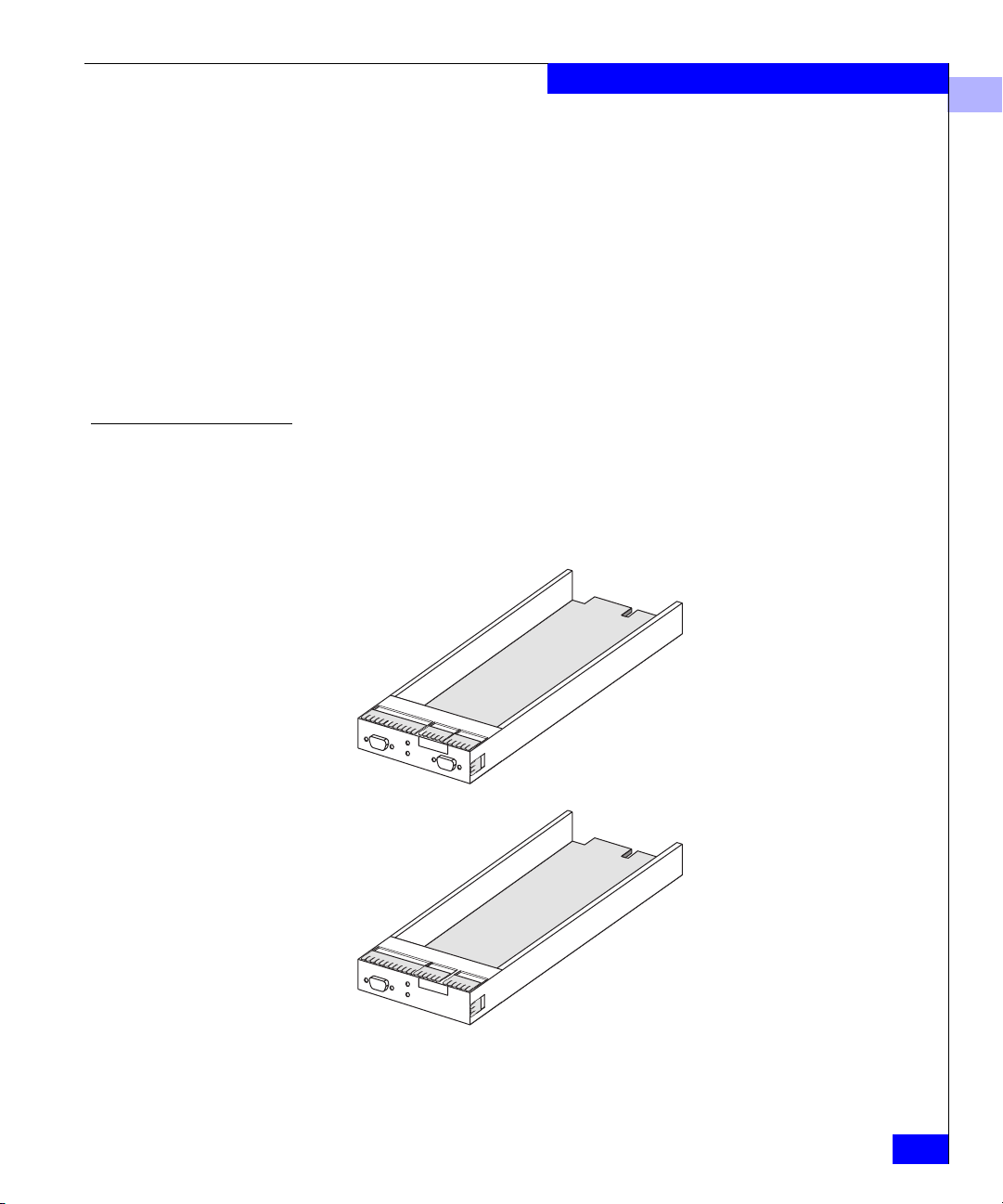
Link Control Cards (LCCs)
The deskside DPE includes two types of LCCs: one type for the DAE
enclosure and another type for the DPE enclosure. LCCs in the DAE
enclosure have a primary connector and an expansion connector.
LCCs in the DPE enclosure have only an expansion connector. The
figure below illustrates both types of LCC.
DAE LCC
DPE LCC
Figure 1-6 Types of LCC
Enclosures
1-9
Page 26
About the Deskside Disk-Array Processor Enclosure
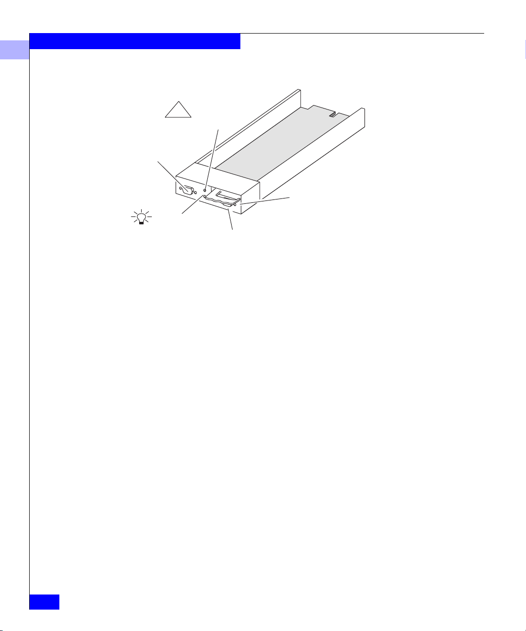
1
!
Check light
(amber)
Expansion FC-AL
EXP
cable connector
Latch
Active light
(green)
Figure 1-7 LCC Ports and Indicators
LCCs support and control the Fibre Channel loops, and monitor the
enclosure environment. You can configure a deskside DPE with LCCs
in A slots or B slots to provide one Fibre Channel loop, or in both A
and B slots to provide two Fibre Channel loops.
Primary FC-AL cable connector (DAE only)
PRI
1-10
An LCC in the DPE is connected to an SP via the midplane. An LCC
in the DAE is connected to the DPE using twin-axial copper cables via
standard DB-9 connectors. The cabling is not explicitly configured as
a loop (that is, a long return from the last DAE to the server), but
instead, as a set of full-duplex, point-to-point connections with the
last DAE in the chain closing the loop on its LCC.
The LCC without the primary connector independently receives and
electrically terminates the incoming FC-AL signal from the SP. The
LCC passes the input signal to its disk drives, and then drives the
output signal, via cables, to the next cabled DAE in the loop, if any.
Each LCC independently monitors the environmental status of the
enclosure using a microcomputer-controlled CRU monitor. The CRU
monitor communicates status to the SP using special protocols. These
protocols let the SP poll deskside DPE status and send commands
that control the LCC port bypass circuit and the disk-module Check
lights.
Each LCC has two status lights. These status lights are described in
the “Monitoring System Status” section of Chapter 3.
EMC Disk-Array Processor Enclosure (DPE) Deskside Model FC4400/4500 Hardware Reference
Page 27
About the Deskside Disk-Array Processor Enclosure
A latch on the LCC locks it into place to ensure proper connection to
the midplane. You can add or replace an LCC while the deskside DPE
is powered up.
1
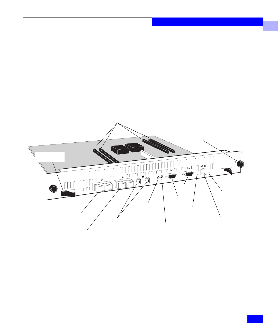
Storage Processors (SPs)
Connectors for DIMMs
Release lever
(2 per SP)
Port A (with optical GBIC)
Port B (with optical GBIC)
The SP is the DPE’s intelligent component. It defines the DPE and
differentiates the DPE from a DAE. An SP is a printed-circuit board
with dual in-line memory modules (DIMMs), a bezel with status
lights, and securing latches. The figure below locates the SP ports (A,
B, SPS/RS-232, Console/RS-232, and network/RJ45), the status
lights, the DIMM memory modules, and the FC-AL ID rotary
switches.
Captive retaining
screw (2 per SP)
SPS
Speed light
Network/RJ45
connection
reserved for
future use
FC-AL ID
switches
Check Light
(amber)
Console
Link/activity light
Active light
(green)
Figure 1-8 SP Back Panel
As shown in the figure, the SP has 4 connectors for DIMMs that
comprise both read and write caches. These DIMMs come in 128-,
256-, or 512-Mbyte capacity. Memory allocation is handled by
Navisphere Manager or other Navisphere array management utility.
Enclosures
1-11
Page 28
About the Deskside Disk-Array Processor Enclosure
1
When the DPE is configured to operate in a fabric environment, only one of
the SP ports (A or B) can be used to connect to the external Fibre Channel
environment.
The SP has two Fibre Channel ports (A and B) referred to as the SP
front end, for connecting to the external Fibre Channel environment.
It also has two rotary switches for setting the FC-AL address ID when
operating in a Fibre Channel Arbitrated Loop environment.
The SP connects to disk modules and to its corresponding LCC via an
internal FC-AL. SP A connects to LCC A, and SP B to LCC B. The
SP-LCC interface is called the SP back end.
The SP also has a console connector (with a terminal icon), a
connector for the standby power supply, marked SPS, and a LAN
connection. Each SP has two status lights visible from the back of the
DPE. For the meaning of these lights, see the “Monitoring DPE
Status” section in Chapter 3.
If a DPE has one SP, you can install a second one while the DPE is
running. When both SPs are installed, you can replace either SP while
the DPE is running. You should never attempt to replace any of the
SP’s components, except the memory modules and GBICs.
1-12
Figure 1-9 Installing an SP
EMC Disk-Array Processor Enclosure (DPE) Deskside Model FC4400/4500 Hardware Reference
Page 29
Power Supplies
About the Deskside Disk-Array Processor Enclosure
The four power supplies are located behind the drive fan pack. Each
power supply is an auto-ranging, power-factor-corrected,
multi-output, off-line converter with its own line cord and on/off
switch. The figure below shows DAE and DPE power supplies. The
DPE power supply is similar to the DAE power supply, differing in
depth (30% deeper), due to the higher power requirements of the
DPE.
ON/OFF switch/breaker
ac inlet
Active light
(green)
!
Check light
(amber)
Latch
1
Cooling Check
light (amber)
Figure 1-10 Power Supply Controls and Indicators
Each supply supports a fully configured DPE/DAE and shares
current with the other “like” supply if one is present. The drive and
LCC voltage lines have individual soft-start switches with
short-circuit current-limit capability. The soft-start switches protect
the disk drives and LCCs if you install them while the deskside DPE
is powered up. A CRU with power-related faults will not adversely
affect the operation of any other CRU.
Power Supplies
1-13
Page 30

About the Deskside Disk-Array Processor Enclosure
1
Each power supply has status lights. These status lights are partially
visible through the drive fan pack, and fully visible with the drive fan
pack removed. The status lights are described in the “Monitoring
system status” section of Chapter .
A latch on the power supply locks it into place to ensure proper
connection to the midplane. You can add or remove a redundant
power supply while the deskside DPE is powered up.
1-14
EMC Disk-Array Processor Enclosure (DPE) Deskside Model FC4400/4500 Hardware Reference
Page 31

Drive Fan Pack
About the Deskside Disk-Array Processor Enclosure
The drive fan pack (see figure below) cools the disk modules, power
supplies, and LCCs in the DPE. A separate pack, described next, cools
the SPs. The drive fan pack contains three fans that draw ambient
room air through the front door, across the drive modules, and
through the midplane and power supplies. The drive fan pack
connects directly to both power supplies, and either supply can
power it. The fans operate at a lower voltage and speed during
normal operation to minimize acoustic noise. If a fan fails, the voltage
and speed of the remaining fans increase to compensate, resulting in
higher acoustic noise.
Check light
!
(amber)
1
Latches
Latches
Figure 1-11 Drive Fan Pack
The drive fan pack has one status light. The status light is visible from
outside the unit, and is described in the “Monitoring System Status”
section of Chapter 3.
Drive Fan Pack
1-15
Page 32

About the Deskside Disk-Array Processor Enclosure
1
You can remove the drive fan pack while the deskside DPE is powered up.
When a drive fan pack is removed, the Cooling Check light on each power
supply flashes.
If the DPE drive fan pack is removed for more than two minutes, the disk
modules and the SPs power down. The disk modules and the SPs power up
again when you reinstall the drive fan pack.
If the DAE drive fan pack is removed for more than two minutes, the disk
modules power down while the Fibre Channel interconnect system continues
operating. The disk modules power up again when you reinstall the drive fan
pack.
SP Fan Pack
The SP fan pack cools the SPs. It contains three fans that draw
ambient room air through the SP fan pack cover, through the
midplane, and across the SPs. The SP fan pack connects to the DPE
midplane via an internal cable, and either supply can power it. The
fans operate at a lower voltage and speed during normal operation to
minimize acoustic noise. If a fan fails, the voltage and speed of the
remaining fans increase to compensate, resulting in higher acoustic
noise.
Latches on the SP fan pack hold it in place. The SP fan pack has one
status light, which is visible when the SP fan pack cover is removed.
The status light is described in the “Monitoring System Status”
section of Chapter 3.
1-16
EMC Disk-Array Processor Enclosure (DPE) Deskside Model FC4400/4500 Hardware Reference
Page 33

Status light
About the Deskside Disk-Array Processor Enclosure
1
IMPORTANT You can remove the SP fan pack
while the DPE is powered up. If the fan pack is
removed for more than about two minutes, the SPs
and disk modules power down. The disk modules and
SPs power up again when you re-install the SP fan
pack.
Figure 1-12 SP Fan Pack
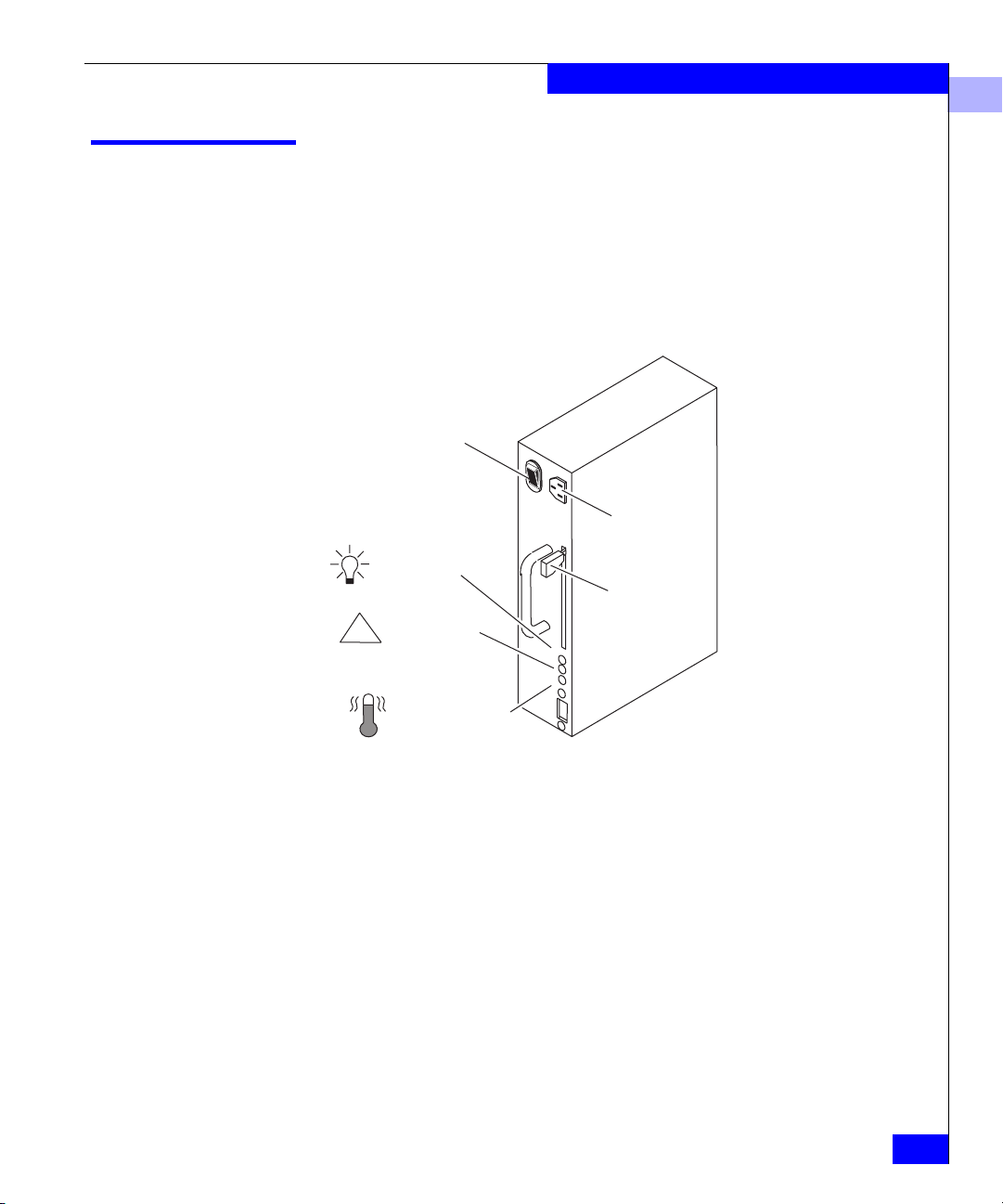
Standby Power Supply (SPS)
Figure 1-13 SPS
The Standby Power Supply (SPS) is an optional component of the
deskside DPE. For configurations using write cache (for example,
RAID 5), an SPS is required. The SPS provides the ac backup power
required to protect the integrity of the Fibre Channel array storage
processor (SP) write cache. The array can use the write cache only
while a fully charged SPS is present. One SPS can maintain the ac
power to the deskside DPE. For higher availability, to allow write
caching to continue when an SPS is faulted or not fully charged, you
can use a second SPS.
Installing an SPS and cabling it to a deskside DPE is explained in the
manual DC Standby Power Supply (SPS) Installation (014002887).
Drive Fan Pack
1-17
Page 34

About the Deskside Disk-Array Processor Enclosure
1
Power Distribution Units (PDUs)
Figure 1-14 PDU
The ac power enters the deskside DPE through the PDU. The
three-outlet PDU provides ac power for two power supplies (one
DAE and one DPE) via their power cords.
Power switch/breaker
Three-outlet PDU
The three-outlet PDU consists of an ac inlet, a circuit breaker, and
three ac outlets. The circuit breaker controls ac power flow to the
outlets. Two three-outlet PDUs are required to power the maximum
configurations.
The three-outlet PDU cannot have two DPE power supplies
connected to it. It is intended for one DPE and one DAE supply.
If you are installing a deskside DPE that includes dual PDUs, you should
plug the PDUs into separate ac source circuits.
1-18
EMC Disk-Array Processor Enclosure (DPE) Deskside Model FC4400/4500 Hardware Reference
Page 35

Redundancy in Configurations
Mirrored storage-system write caching requires:
• Two SPs with equal memory of at least 128 Mbytes
• Two power supplies
• Two LCCs in the DPE and each DAE
• Disks in slots 0:0 through 0:8
• SPS (standby power supply) with a fully charged battery
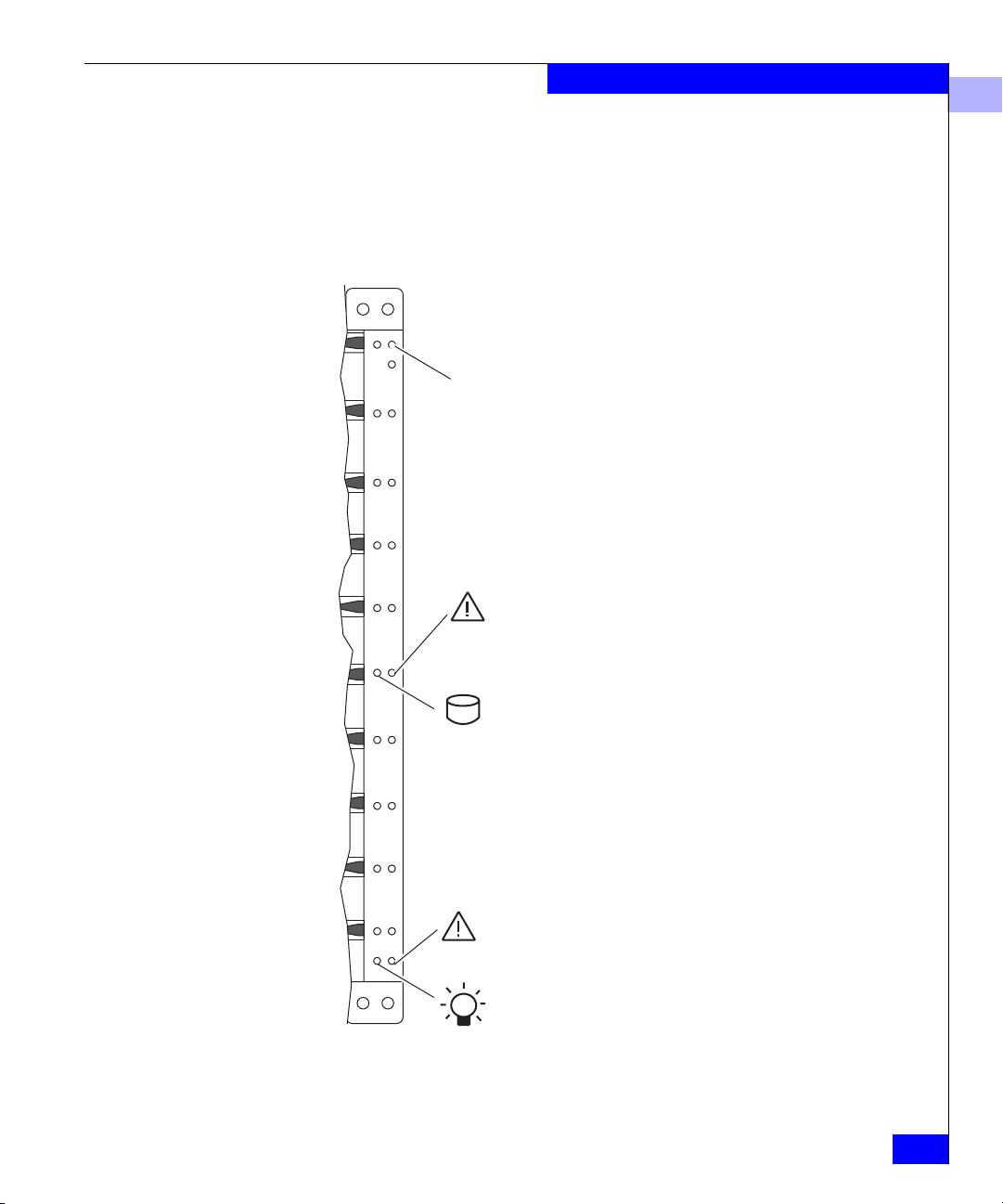
The following figures illustrate which disk modules in a deskside
DPE are the database and cache vault drives.
A module designated as database or cache vault drive cannot be configured
as a hot spare
About the Deskside Disk-Array Processor Enclosure
1
10-Slot Deskside DPE
0
1
2
3
4
5
6
cache
7
8
9
Figure 1-15 Disk Modules in a Deskside DPE
vault
(DPE)
Database
drives for
LIC
(0 thru2)
Vault
drives for
caching
(3 thru 8)
The following table describes the deskside DPE high availability
configurations.
20-Slot Deskside DPE
0
1
2
3
4
5
6
7
8
9
10
11
12
13
14
15
16
17
18
19
Redundancy in Configurations
1-19
Page 36

About the Deskside Disk-Array Processor Enclosure
1
Deskside DPE PDUs SPs LCCs
High Availability
Configurations
2
2
2
2
2
2
2 DPE
2 DAE
2 DPE
2 DAE
2 DPE
2 DAE
The maximum configurations provide more redundancy, and
therefore a higher degree of system availability. The minimum
configuration provides less redundancy, and therefore is not highly
available.
The drive fan packs and SP fan pack provide redundant cooling for
all configurations. Dual three-outlet PDUs provide redundant ac
power.
Power
Supplies
2 DPE
2 DAE
2 DPE
2 DAE
2 DPE
2 DAE
Disk
Modules
5 or more
10 or more
10 or more
SPSs
0 (no write caching)
1 (minimum for write caching)
2 (high-availability write caching)
1-20
Fan packs
LCCs
Figure 1-16 Back View Showing Components
EMC Disk-Array Processor Enclosure (DPE) Deskside Model FC4400/4500 Hardware Reference
SPs
Page 37

About the Deskside Disk-Array Processor Enclosure
Components of a deskside DPE have slot designations as shown in
the following figures. For example, a power supply in slot A is
referred to as PS A, or an LCC in slot B is referred to as LCC B.
1
DAE LCC A
DAEPSA
DAEPSB
DAE LCC B
DPE LCC A
DPEPSA
DPEPSB
SP B
SP A
PDU A
PDU B
Figure 1-17 High Availability Configuration, No Write Caching, Back View with
Cables and Drive Fan Packs Removed
DPE LCC B
SPS filler
(in slot A)
Redundancy in Configurations
SPS filler
(in slot B)
1-21
Page 38

About the Deskside Disk-Array Processor Enclosure
1
SP A is associated with LCC A. SP B is associated with LCC B.
DAE LCC A
DAE PS A
DAE PS B
DAE LCC B
DPE LCC A
DPEPSA
DPEPSB
SP B
SP A
1-22
PDU A
PDU B
Figure 1-18 High Availability Configuration, Minimum Write Caching, Back View
DPE LCC B
SPS A
SPS filler
with Cables and Drive Fan Packs Removed
SP A is associated with LCC A. SP B is associated with LCC B.
EMC Disk-Array Processor Enclosure (DPE) Deskside Model FC4400/4500 Hardware Reference
Page 39

About the Deskside Disk-Array Processor Enclosure
1
DAE LCC A
DAE PS A
DAE PS B
DAE LCC B
DPE LCC A
DPEPSA
DPEPSB
SP B
SP A
PDU A
PDU B
Figure 1-19 High Availability Configuration, Write Caching High Availability, Back
DPE LCC B
SPS A
SPS B
View with Cables and Drive Fan Packs Removed
SP A is associated with LCC A. SP B is associated with LCC B.
Redundancy in Configurations
1-23
Page 40

About the Deskside Disk-Array Processor Enclosure
1
EMI Compliance
A deskside DPE has two sets of compliance labels. There is one label
for the deskside system, and one label for each enclosure.
The rating label of the entire deskside DPE is located as shown below.
1-24
Location of compliance labels
Figure 1-20 Compliance Label Locations
EMC Disk-Array Processor Enclosure (DPE) Deskside Model FC4400/4500 Hardware Reference
Page 41

What Next?
About the Deskside Disk-Array Processor Enclosure
1
Continue to Chapter 2 to install the DPE.
What Next?
1-25
Page 42

About the Deskside Disk-Array Processor Enclosure
1
1-26
EMC Disk-Array Processor Enclosure (DPE) Deskside Model FC4400/4500 Hardware Reference
Page 43

2
Installing a Deskside
DPE
This chapter describes the DPE installation requirements and
procedures. Major topics include:
• Requirements......................................................................................2-2
• Installing a Deskside DPE.................................................................2-4
• Deskside DPE Powerup and Initialization Sequence.................2-15
• DPE Powerdown..............................................................................2-16
• Binding Disk Modules into RAID Groups...................................2-18
Installing a Deskside DPE
2-1
Page 44

Installing a Deskside DPE
2
Requirements
This section explains site, cabling, and addressing requirements.
Site Requirements
Grounding The deskside DPE is grounded through its power cord, as is the
Power To determi ne a DPE’s power requirements, use the power rating on
For proper DPE operation, the installation site must conform to
certain environmental specifications. These are detailed below and in
Appendix A.
server and other FC devices. If the DPE is configured for an FC-AL
environment using copper FC-AL cables, we suggest that all
interconnected devices on the loop be connected to a common
ground grid. Optical cables do not have these ground requirements.
the enclosure label. This rating is the maximum power required for a
fully loaded enclosure. The input current, power (VA), and
dissipation for the DPE are based on the maximum capability of the
power supplies and cooling system to provide internally regulated
power.
Typical values will be less depending on the number and
manufacturer of disk drives. These values represent either the values
for the power cord of a deskside DPE with a non-redundant single
power supply configuration and PDU, or the total values shared by
the power cords of redundant power supplies, with the division
between the power cords and supplies at the current sharing ratio. If
a redundant power supplies fails, the remaining supply(s) and
cord(s) support the full load.
Cooling The ambient temperature specification is measured at the front door
inlet. The site must have air conditioning of the correct size and
placement to maintain the specified ambient temperature range. The
air conditioning must be able to handle the BTU requirements of the
deskside DPE.
Cabling Requirements Use optical or copper cables for connections to the external Fibre
Channel environment. Use a copper cable only (not an optical cable)
to connect a DPE to a DAE.
DPE and DAE interconnections should maintain LCC consistency;
that is, one FC loop should connect the DPE’s SP A (which connects
internally to LCC A) and each DAE’s LCC A. The other FC loop
should connect the DPE’s SP B (which connects internally to LCC B)
2-2
EMC Disk-Array Processor Enclosure (DPE) Deskside Model FC4400/4500 Hardware Reference
Page 45

Installing a Deskside DPE
and each DAE’s LCC B. Do not leave an unused (that is, dangling)
cable connected to any Fibre Channel port because it may cause
excess noise on the Fibre Channel.
2
Addressing Requirements
The addressing requirements vary depending on the environment,
fibre port (fabric) or fibre loop (FC-AL).
Fabric Environments In a fabric environment, the DPE is addressed using the Source_ID
(SID) and the enclosure address (EA).
Source_ID
The Source_ID (SID) is a value that a switch in the external Fibre
Channel environment automatically assigns.
Enclosure Address (EA)
Each DPE and DAE on a back-end loop needs a unique enclosure
address (EA) that identifies the enclosure and determines disk
module addresses. The DPE has a fixed EA of 0 that you cannot
change. If you cable any DAEs to the DPE, you might want to set the
nearest DAE’s EA to 1, the next to 2, and so on. The enclosure address
is displayed in lights visible behind the front door.
Loop Environments In an FC-AL environment, the DPE is addressed using the FC-AL
address ID and the enclosure address (EA).
Fibre Channel Arbitrated Loop Address ID (FC-AL Address ID)
Each node (such as an SP) on the Fibre Channel front-end loop must
have a unique Fibre Channel arbitrated loop address ID (FC-AL
address ID). The FC-AL protocol translates the FC-AL address ID into
an 8-bit arbitrated loop physical address (ALPA). You set the SP
FC-AL address ID using switches, as explained later in this chapter.
Enclosure Address (EA)
Each DPE and DAE on a back-end loop needs a unique enclosure
address (EA) that identifies the enclosure and determines disk
module addresses. The DPE has a fixed EA of 0 that you cannot
change. If you cable any DAEs to the DPE, you might want to set the
nearest DAE’s EA to 1, the next to 2, and so on. The enclosure address
is displayed in lights visible behind the front door.
Requirements
2-3
Page 46

Installing a Deskside DPE
2
Installing a Deskside DPE
WARNING
The deskside DPE is heavy. To avoid injury, do not try to lift it.
WARNING
Das Deskside-DAE ist schwer. Zur Vermeidung von körperlichen
Verletzungen, bitte nicht anheben.
1. Unlock the DPE’s front wheels, as shown below, and roll it into
position.
2. Lock the DPE’s front wheels as shown next.
To lock front wheels
2-4
To unlock front wheels
Figure 2-1 Locking and Unlocking the Front Wheels
3. At the back of the deskside DPE, set each PDU power switch to 0
(off).
EMC Disk-Array Processor Enclosure (DPE) Deskside Model FC4400/4500 Hardware Reference
Page 47

Power switch
Figure 2-2 Turning Power Off
4. Unlock and open the DAE front door as shown below.
Installing a Deskside DPE
2
Key
Latch
A. If the door is locked:
Insert the key in the door’s latch.
Turn the key 180 degrees clockwise
B. Push the door’s latch.
C. Swing the door to the left.
Figure 2-3 Unlocking and Opening the Front Door
CAUTION Do not force the door
open. If the door snaps off the hinges,
reinstall it by positioning it at a 45-degree
angle to the enclosure and snapping it
into the hinge openings.
5. Each DAE must have a unique enclosure address (EA), referred to
as the back-end address, that identifies the DAE and determines
disk module addresses. Because the back-end address 0 is
Installing a Deskside DPE
2-5
Page 48

Installing a Deskside DPE
s
h
h
2
reserved for the DPE, valid EA ranges for the DAE are 1 through
11 (decimal). We recommend that you assign address number 1 to
the DAE closest to the DPE.
Set the EA with the EA switch, which has one push button for
incrementing the address and another for decrementing it. To set
the EA, you must open the DAE’s front door. The switches have
lights that display the EA address. These lights are visible when
the door is closed.
Set the DAE enclosure address (EA) to the desired value using the
tip of a pen or paper clip, as shown below.
00
1
2
3
4
5
1236
7
8
9
10
11
Enclosure
address lights
Increment button
Push to increase address.
2
Decrement button
Push to decrease address.
Figure 2-4 Setting the Enclosure Address (EA)
6. Close the DAE front door as shown on the next page.
The door must be closed for EMI compliance. Open it only to service the
DPE or DAE.
Address
switch
NOTE: The addres
switch has 16 positions, 12 are marke
0 through 11 and t
remaining 4 are
marked with a das
(-). A dash position
is equivalent to the
position.
2-6
EMC Disk-Array Processor Enclosure (DPE) Deskside Model FC4400/4500 Hardware Reference
Page 49

Installing a Deskside DPE
Key
2
A. Swing the door
to the right.
Figure 2-5 Closing and Locking the Front Door
B. To lock the door:
Insert the key in the door’s latch.
Turn the key 180 degrees counterclockwise.
Remove the key, if desired.
7. Perform this step only if you are installing the DPE into an FC-AL
environment. Otherwise, continue to the next step.
To communicate in an FC-AL environment, each SP requires a
unique FC-AL address ID (the front-end address). The FC-AL
protocol translates the address ID into an 8-bit arbitrated loop
physical address (ALPA). Valid Fibre Channel address IDs range
from 0 through 125 (decimal) (0 through 7D hexidecimal).
Each SP’s Fibre Channel address ID must be unique on the Fibre Channel
loop.
At the back of the deskside DPE, use the SP FC-AL ID switches to
set the address ID for each SP (refer to the figure and table on the
next page).
Installing a Deskside DPE
2-7
Page 50

Installing a Deskside DPE
2
4
5
Figure 2-6 Storage Processor FC-AL ID Switches
FC-AL Address ID
(Decimal) Bottom Switch Setting Top Switch Setting
3
2
1
0
F
E
3
2
1
0
6
7
8
9
A
B
D
C
4
5
6
7
8
2-8
00 0
10 1
.
.
.
.
.
.
.
.
.
15 0 F
16 1 0
.
.
.
.
.
.
.
.
.
31 1 F
32 2 0
.
.
.
.
.
.
.
.
.
125 7 D
EMC Disk-Array Processor Enclosure (DPE) Deskside Model FC4400/4500 Hardware Reference
Page 51

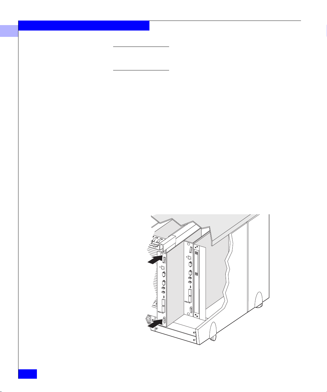
8. Plug one end of the power cord into the ac receptacle on each
PDU, leaving the other end unplugged.
Figure 2-7 Connecting the Power Cord
9. Attach the Fibre Channel cable from the external Fibre Channel
environment to SP Port A or B as shown on the next page.
When working with optical cables, observe the following precautions:
Installing a Deskside DPE
2
Dual three-outlet PDUs
• Keep the covers on all optical cables and optical GBICs until
you are ready to insert the cables. The covers protect the cables
and connectors, and prevent foreign particles, such as dust,
from entering and affecting the connection.
• Do not leave an unused (that is, dangling) cable, connected to
an SP port because it may cause excess noise on the loop.
• Avoid tight bends. If you need to make a 90º bend, do it over a
length of 6 to 12 inches.
• Do not use optical cables to support weight. That includes
long cable runs without support.
• Do not pull long runs of cable. Lay the cable in place or pull
only a few feet at a time.
• Run the cables so that they are not stepped on or rolled over
by anything.
Installing a Deskside DPE
2-9
Page 52

Installing a Deskside DPE
2
Optical GBIC
connector
B
A
A. Remove the protective
covers from each optical
GBIC connector and each
fibre optic cable.
Cover
Covers
Fibre
optic
cables
B. Plug the fibre optic cable
into Port A and/or Port B
on the SP.
2-10
Figure 2-8 Attaching Optical Cables to a DPE
EMC Disk-Array Processor Enclosure (DPE) Deskside Model FC4400/4500 Hardware Reference
Page 53

Installing a Deskside DPE
2
Copper GBIC connector
B
Screw
A
Copper cable
A. Plug the copper cable into Port
A and/or Port B on the SP.
Figure 2-9 Attaching Copper Cables to a DPE
B. Tighten the two screws to secure
the cable in place.
Installing a Deskside DPE
2-11
Page 54

Installing a Deskside DPE
2
10. Connect the LCC in the DAE to the LCC in the DPE using copper
cables as shown below.
DAE LCC
PRI
EXP
2-12
A.
Plug one end of the copper cable into
the expansion (EXP) connector on
the DPE LCC.
B.
Tighten the two screws on the
cable’s connector.
C.
Plug the other end of the copper
cable into the primary (PRI)
connector on the DAE LCC.
D.
Tighten the two screws on the
cable’s connector.
Figure 2-10 Cabling a DPE to a DAE
EMC Disk-Array Processor Enclosure (DPE) Deskside Model FC4400/4500 Hardware Reference
DPE LCC
Page 55

Installing a Deskside DPE
11. If you want to daisy-chain multiple deskside DAEs, cable them
together with copper cables only. Refer to the illustration that
follows.
2
A. Plug one end of the copper cable into the
expansion (EXP) connector on the DAE
LCC in the deskside DPE.
B. Tighten the two screws on the
cable’s connector.
Primary connector
PRI
Copper cable
LCC to LCC
Expansion connector
C. Plug the other end of the copper
cable into the primary (PRI)
connector on the add-on LCC in
the 10-slot DAE.
D. Tighten the two screws on the
cable’s connector.
Figure 2-11 Daisy-Chaining a 10-Slot Deskside DAE from a Deskside DPE with
Copper Cable
12. Make sure all the slots in the deskside DPE contain either CRUs
or filler modules (for proper cooling and normal operation).
Installing a Deskside DPE
EXP
2-13
Page 56

Installing a Deskside DPE
2
When you connect multiple DAEs using the same Fibre Channel
arbitrated loop, retiming is required to maintain signal integrity. The
drive modules in each DAE must provide this timing, and each DAE
must be configured with at least two operational drive modules per
enclosure, one in an even numbered slot, and one in an odd numbered
slot (only one is required for the last DAE in the chain).
If you are installing a highly available deskside DPE, we
recommend that you plug the PDUs into separate ac source
circuits.
13. Plug the PDU ac input power cord(s) into the ac source
receptacle(s).
Do not power up a DPE without at least one LCC installed.
14. Set the power switch on each PDU to 1 (on).
2-14
Power switch
Figure 2-12 Turning Power On
The Active light on each power supply, which is visible through
the drive fan pack, should be on. If it stays off, remove the drive
fan pack and ensure that the power switch on the power supply is
set to 1 (on) (see Chapter 3).
EMC Disk-Array Processor Enclosure (DPE) Deskside Model FC4400/4500 Hardware Reference
Page 57

Deskside DPE Powerup and Initialization Sequence
You apply power to a deskside DPE by setting the power switch on
each PDU to 1 (on). When you apply power, the disk drives power up
according to their specifications, and spin up in a specified sequence.
The slot spin-up delays are multiples of 12 seconds. The maximum
delay is 84 seconds. These delays also apply to drives inserted while a
deskside DPE is powered up. Spindle synchronization is supported
within enclosures, but not between enclosures.
The LCC CRU monitor resets and begins its control loop. The drives
set the state of the port bypass circuit. The CRU monitor continues to
run in this local mode until it receives SP commands that dictate
otherwise.
The drives and SPs read their Fibre Channel address ID only at
powerup or when reset. As a result, you must set the DAE enclosure
address and SP addresses while power is off. You cannot change the
address while power is on.
Installing a Deskside DPE
2
Deskside DPE Powerup and Initialization Sequence
2-15
Page 58

Installing a Deskside DPE
2
DPE Powerdown
If a DPE (with an SPS option) is powered down abnormally (for
example, if the plug is accidentally disconnected or a power failure
occurs), data is saved to the storage-system vault disks, not lost.
However, when the DPE is powered up again, it will take longer to
come on line because it first must write the vault disk data to the
correct LUNs.
Turning Off Power Correctly
1. Stop any I/O activity to the DPE.
2. If the server connected to the DPE is running the UNIX®
operating system, unmount the file systems.
3. If the DAE does not have SPS protection, use the circuit breaker
on each PDU to turn off power.
PDU power switches
2-16
Figure 2-13 Powering Down
When you turn off power to a storage system with an SPS, the On
Battery light may come on for a maximum of 90 seconds during
which time the DPE will continue to run. This is a normal
condition. Wait for the light to go off and the fans to stop before
proceeding with further service to the storage system.
EMC Disk-Array Processor Enclosure (DPE) Deskside Model FC4400/4500 Hardware Reference
Page 59

Installing a Deskside DPE
Never remove the fan pack and then shut off the power supply to shut
down an DPE. Shutting off power in that way eliminates the SPS
function, saving write cache data to the vault drives, and results in a
cache dirty condition (data loss). When that happens, LUNs become
inaccessible and the unsolicited event log displays a message similar to:
Enclosure 0 Disk 5 0x90a (Can’t Assign - Cache Dirty)
0 0xafb40 0x14362c. Navisphere® Manager or Supervisor will
show that the inaccessible LUNs are unowned. Contact your service
provider if this situation occurs. The LUNs may need to be unbound and
rebound.
2
Turning On Power
Reverse the steps to power up the DPE.
DPE Powerdown
2-17
Page 60

Installing a Deskside DPE
2
Binding Disk Modules into RAID Groups
After installing the deskside DPE, you can bind disk modules into
RAID groups and set up storage-system caching (refer to the server
setup manual).
2-18
EMC Disk-Array Processor Enclosure (DPE) Deskside Model FC4400/4500 Hardware Reference
Page 61

3
Servicing and
Upgrading a Deskside
DPE
This chapter describes how to service the deskside DPE. Major
topics include:
• Monitoring System Status.................................................................3-2
• Handling CRUs ..................................................................................3-8
• Precautions When Handling Optical Cables ............................... 3-11
• Replacing or Adding a Disk Module ............................................3-12
• Replacing the SP Fan Pack..............................................................3-17
• Replacing an Optical GBIC.............................................................3-20
• Replacing a Copper GBIC...............................................................3-25
• Removing an SP or an SP Filler Module.......................................3-29
• Installing or Replacing an SP Memory Module ..........................3-31
• Installing an SP or SP Filler Module..............................................3-34
• Replacing or Adding an LCC Module..........................................3-37
• Replacing the Drive Fan Pack ........................................................3-43
• Replacing or Adding a Power Supply Module ...........................3-46
During normal deskside DPE operation, all compartments should
contain either a module or filler, and the front door(s) should be
closed. This ensures EMI compliance and proper air flow (cooling)
within the unit.
The deskside DPE is designed for continuous operation, and it
should always be powered up. You can replace any disk module,
redundant LCC, redundant power supply, or fan pack while the
deskside DPE is running.
Servicing and Upgrading a Deskside DPE
3-1
Page 62

Servicing and Upgrading a Deskside DPE
3
Monitoring System Status
The deskside DPE status lights indicate system and component
conditions. These lights are visible from outside the front or back of
the deskside DPE. The following tables describe the location, color,
and meaning of these status lights.
The Check status light for the SP fan pack is not visible with the fan pack
cover in place. If the DPE’s system Check light is on with no other Check light
on, remove the fan pack cover, as shown on on page x-17, to examine the SP
fan pack Check status light.
0
1
2
3
4
5
6
7
8
9
Enclosure address light
Disk Check
Disk module status lights (two
per module)
Disk Active
System Check
DPE status lights
3-2
Power
Figure 3-1 DPE Front Panel
EMC Disk-Array Processor Enclosure (DPE) Deskside Model FC4400/4500 Hardware Reference
Page 63

Servicing and Upgrading a Deskside DPE
Table 3- 1 Status Lights Visible on the DPE Front Panel
Light Quantity Color Meaning
DPE Power 1 Green On when the deskside DPE is powered up.
DPE System Check 1 Amber On when any fault condition exists.
Disk Active 1 per disk
module slot
Green Off when the disk module slot is empty or contains a filler.
Flashing (mostly off) when the drive is powered up but not spinning; a
normal part of the spin-up sequence, occurring during the spin-up delay
of the slot.
Flashing (at a constant rate) when the disk drive is spinning up or
spinning down normally.
On when the drive is spinning but not handling any I/O activity (the ready
state).
Flashing (mostly on) when the disk drive is spinning and handling I/O
activity.
Disk Check 1 per disk
module slot
Amber On when the disk module is faulty, or as an indication to remove the disk
module.
Enclosure Address 1 Green On to indicate enclosure address zero.
3
Monitoring System Status
3-3
Page 64

Servicing and Upgrading a Deskside DPE
3
Table 3- 2 Status Light Visible on the SP Fan Module
Light Quantity Color Meaning
SP Fan pack Check 1 on SP drive fan pack Amber On when an SP fan pack is faulty (not visible when SP fan
pack cover is on; the cover is easily pulled off).
3-4
EMC Disk-Array Processor Enclosure (DPE) Deskside Model FC4400/4500 Hardware Reference
Page 65

Servicing and Upgrading a Deskside DPE
Table 3- 3 Status Lights Visible from the Back of the Deskside DPE
Light Quantity Color Meaning
SP Active 1 per SP Green On when the SP is operating normally
or flashing when firmware is being loaded.
SP Check 1 per SP Amber On when an SP fault exists.
LAN Link/Activity 1 per SP Green On when there is a valid Ethernet connection; blinks during
Ethernet activity
LAN Speed 1 per SP Amber On when the Ethernet connection is a 100Base-TX connection
LCC Active 1 per LCC Green On when the LCC is powered up.
LCC Check 1 per LCC Amber On when either the LCC or a Fibre Channel connection is
faulty.
Power supply Active 1 per supply Green On when the power supply is operating.
Power supply Check 1 per supply Amber On when the power supply is faulty or is not receiving ac line
voltage.
Cooling Check 1 per supply Amber Flashing when multiple fans in the drive fan pack are faulty or
the drive fan pack is removed. If the error condition continues
for more than two minutes, and the faulty fan pack is the DAE
fan pack, the deskside DPE powers down the disk drives. If the
error condition continues for more than two minutes, and the
faulty fan pack is the DPE fan pack, the deskside DPE powers
down the disk drives and the SPs.
Drive Fan pack Check 1 per drive fan pack Yellow On when a fan in the drive fan pack is faulty.
3
Monitoring System Status
3-5
Page 66

Servicing and Upgrading a Deskside DPE
3
Enclosure address lights
Enclosure address switch
(not visible with front door
closed)
Disk Check
Disk module status lights
(two per module)
3-6
Disk Active
System Check
DAE status lights
Power
Figure 3-2 DAE Front Panel
EMC Disk-Array Processor Enclosure (DPE) Deskside Model FC4400/4500 Hardware Reference
Page 67

Servicing and Upgrading a Deskside DPE
Table 3- 4 Status Lights Visible on the DAE Front Panel
Light Quantity Color Meaning
DAE Power 1 Green On when the deskside DPE is powered up.
DAE System Check 1 Amber On when any fault condition exists.
Drive Active 1 per disk module slot Green Off when the disk module slot is empty or contains a filler
module.
Flashing (mostly off) when the drive is powered up but not
spinning; a normal part of the spin-up sequence, occurring
during the spin-up delay of the slot.
Flashing (at a constant rate) when the disk drive is spinning up
or spinning down normally.
On when the drive is spinning but not handling any I/O activity
(the ready state).
Flashing (mostly on) when the disk drive is spinning and
handling I/O activity.
Disk Check 1 per disk module slot Amber On when the disk module is faulty, or as an indication to remove
the drive.
Enclosure Address 12 Green One of twelve is lit to indicate the enclosure address.
If the DPE or DAE Check light is on, you should look at the other
Check lights to determine which CRU is faulty. If the Check light on a
CRU remains on, you should replace that CRU as soon as possible.
3
If a non-redundant CRU fails in a deskside DPE, the system may be
inoperable while you replace the CRU. If a redundant CRU fails, high
availability and any write cache functionality will be compromised
until you replace the faulty CRU.
Monitoring System Status
3-7
Page 68

Servicing and Upgrading a Deskside DPE
3
Handling CRUs
This section describes the precautions that you must take, and the
general procedures you must follow when removing, installing, and
storing CRUs.
Power Issues and CRUs
Avoiding Electrostatic Discharge (ESD) Damage
The deskside DPE is designed to be powered up at all times and to be
hot repairable. Its front door should be closed and each compartment
should contain a CRU or filler panel to ensure EMI compliance and
proper air flow over the CRUs.
While the DPE is powered up, you can service or replace any CRU,
although removing an active LCC or SP will affect operating system
access to the LUNs it controls. Do not remove a faulty CRU until you
have a replacement available.
You can remove the SP fan pack while the DPE is powered up. If the fan pack
is removed for more than about two minutes, the SPs and disk modules
power down. The disk modules and SPs power up again when you reinstall
the SP fan pack.
If the DPE drive fan pack is removed for more than two minutes, the disk
modules and the SPs power down. The disk modules and the SPs power up
again when you reinstall the drive fan pack.
If the DAE drive fan pack is removed for more than two minutes, the disk
modules power down while the Fibre Channel interconnect system continues
operating. The disk modules power up again when you reinstall the drive fan
pack.
When you replace or install CRUs, you can inadvertently damage the
sensitive electronic circuits in the equipment by simply touching
them. Electrostatic charge that has accumulated on your body
discharges through the circuits. If the air in the work area is very dry,
running a humidifier in the work area will help decrease the risk of
ESD damage. You must read and understand the procedures below to
prevent damage to the equipment.
3-8
Read and understand the following instructions.
EMC Disk-Array Processor Enclosure (DPE) Deskside Model FC4400/4500 Hardware Reference
Page 69

Servicing and Upgrading a Deskside DPE
• Provide enough room to work on the equipment. Clear the
work site of any unnecessary materials or materials that
naturally build up electrostatic charge, such as foam
packaging, foam cups, cellophane wrappers, and similar
materials.
• Do not remove replacement or upgrade CRUs from their
antistatic packaging until the exact moment that you are ready
to install them.
• Gather together the ESD kit and all other materials you will
need before you service a deskside DPE. Once servicing
begins, you should avoid moving away from the work site;
otherwise, you may build up an electrostatic charge.
• Use the ESD kit when handling any CRU. If an emergency
arises and the ESD kit is not available, follow the procedures
in the “Emergency procedures (without an ESD kit)” section.
An ESD wristband (part no. 129002319) is supplied with your
DPE.
3
Emergency Procedures (without an ESD Kit)
In an emergency when an ESD kit is not available, use the following
procedures to reduce the possibility of an electrostatic discharge by
ensuring that your body and the subassembly are at the same
electrostatic potential.
These procedures are not a substitute for the use of an ESD kit. Follow them
only in the event of an emergency.
• Before touching any CRU, touch a bare (unpainted) metal surface
of the enclosure.
• Before removing any CRU from its antistatic bag, place one hand
firmly on a bare metal surface of the enclosure, and at the same
time, pick up the CRU while it is still sealed in the antistatic bag.
Once you have done this, do not move around the room or contact
other furnishings, personnel, or surfaces until you have installed
the CRU.
• When you remove a CRU from the antistatic bag, avoid touching
any electronic components and circuits on it.
Handling CRUs
3-9
Page 70

Servicing and Upgrading a Deskside DPE
3
• If you must move around the room or touch other surfaces before
installing a CRU, first place the CRU back in the antistatic bag.
When you are ready again to install the CRU, repeat these
procedures.
Precautions When Removing, Installing, or Storing CRUs
Use the precautions listed below when you remove, handle, or store
CRUs.
• Do not remove a faulty CRU until you have a replacement
available.
• Ensure that the front wheels on the deskside DPE are locked
before installing or removing a CRU.
• Handle a CRU only when using an ESD wristband as follows:
attach the clip of the ESD wristband to the ESD bracket or bare
metal on the enclosure, and put the wristband around your wrist
with the metal button against your skin.
• Handle CRUs gently. A sudden jar, drop, or vibration can
permanently damage a CRU.
• Place one hand on top of the deskside DPE to prevent movement
while installing or removing CRUs.
• Never use excessive force to remove or install a CRU.
• Store a CRU in an antistatic bag, in the specially designed
shipping container in which you received it, and use that bag and
container if you need to return the CRU for repair.
• Maintain the location where you store CRUs within the limits
specified in Appendix A.
3-10
EMC Disk-Array Processor Enclosure (DPE) Deskside Model FC4400/4500 Hardware Reference
Page 71

Precautions When Handling Optical Cables
When working with optical cables, observe the following
precautions:
• Keep the covers on all optical cables and optical GBICs until you
are ready to insert the cables. The covers protect the cables and
connectors, and prevent foreign particles, such as dust, from
entering and affecting the connection.
• Avoid tight bends. If you need to make a 90º bend, do it over a
length of 6 to 12 inches.
• Do not use optical cables to support weight (including long cable
runs without support).
• Do not pull long runs of cable. Lay the cable in place or pull only
a few feet at a time.
• Run the cable so that it is not stepped on or rolled over by
anything.
Servicing and Upgrading a Deskside DPE
3
Precautions When Handling Optical Cables
3-11
Page 72

Servicing and Upgrading a Deskside DPE
3
Replacing or Adding a Disk Module
!
CAUTION
When replacing or adding a disk module, observe the following:
• Remove or install disk modules only while the storage system is
powered up.
• Do not move a disk module that is part of an existing LUN to
another slot in the storage system. If you do, you risk destroying
the storage system beyond recovery, or data loss at the very least.
Each disk module has LUN-identifying information assigned to it
when it is bound. Moving it to another slot can make the
information stored on the disk module from the original LUN
inaccessible. If you must move a disk module to another slot,
unbind the LUN first; unbinding destroys all data on the LUN.
• A disk module must be inserted all the way or removed entirely.
Do not leave a disk module partially removed except for periods
when you are allowing it to spin down. A disk module being
inserted or removed may be damaged by a partially removed
adjacent module.
• Handle a disk module gently and use an ESD wristband. Do not
remove a faulty disk module until you have a replacement
module (with the same part number) or a filler module available.
The part number (PN005xxxxxx) appears on the top or bottom of
the module. A replacement or add-on disk module should have
the same format (520- or 512-byte sectors) and the same capacity
(size & speed) as the other modules in the enclosure.
3-12
• When removing or installing multiple disk modules, wait for the
activity lights on all other disk modules to resume a steady flicker
before removing or installing the next disk module. The activity
lights show that the LIC (licensed internal code) has rediscovered
the FC loop.
If you want to use a previously used disk module as a spare, contact your
service provider for assistance.
You must open the DPE’s front door to access the disk modules. The
door must be closed for EMI compliance when the DPE is powered
up. Open it only to replace or add a disk module.
EMC Disk-Array Processor Enclosure (DPE) Deskside Model FC4400/4500 Hardware Reference
Page 73

Servicing and Upgrading a Deskside DPE
3
Removing a Disk or Disk Filler Module
1. Unlock and open the front door as shown below.
Key
Latch
A. If the door is locked:
Insert the key in the door’s latch.
Turn the key 180 degrees clockwise.
Swing the door to the left.
B. Push the door’s latch.
C. Swing the door to the left.
CAUTION Do not force the
door open. If the door snaps off
the hinges, reinstall it by
positioning it at a 45-degree
angle to the enclosure and
snapping it into the hinge
Figure 3-3 Unlocking and Opening the Front Door
2. Locate the slot where you want to install the new or replacement
disk module.
3. Remove the disk or disk filler module from the slot as shown
below and on the next page.
Replacing or Adding a Disk Module
3-13
Page 74

Servicing and Upgrading a Deskside DPE
u
3
A.
Grasp the disk module filler handle
so that your thumb is on the latch.
B.
Push the latch, and slowly pull the
module from its slot.
Latch
Figure 3-4 Removing a Disk Filler Module
A. Grasp the disk module handle
so that your thumb is on the latch.
3-14
B. If the active light is on steadily, push
the latch, and slowly pull the module abo
3 cm (1 inch) from its slot. Wait 30
Latch
Figure 3-5 Removing a Disk Module
After removing a disk module, wait for the activity lights on the other disk
modules to resume a steady flicker before removing another disk module.
The activity lights show that the licensed internal code (LIC) has
rediscovered the FC loop.
seconds for the disk to stop spinning.
Then remove the module.
If the active light is off or mostly off,
you do not need to wait for the disk to stop
spinning. Push the latch, and slowly pull th
module from its slot.
Continue to the next section to install the new or replacement disk
module.
EMC Disk-Array Processor Enclosure (DPE) Deskside Model FC4400/4500 Hardware Reference
Page 75

Servicing and Upgrading a Deskside DPE
3
Installing a Disk Module
Figure 3-6 Installing a Disk Module
1. Gently insert the add-on or replacement disk module as follows:
A.
Grasp the disk module’s handle
with one hand and support the
module with your other hand.
B.
Align the module with the
guides in the slot.
C.
Gently push the
module into the slot
until the latch engages.
Latch
The disk module’s Active light flashes to reflect the disk’s spin-up
sequence (see page 3-3).
After inserting a disk module, wait for the activity lights on the other
drives to resume a steady flicker before inserting another module. The
activity lights show that the LIC has rediscovered the FC loop.
2. Remove and store the ESD wristband.
The door must be closed for EMI compliance when the DPE is powered
up. Open it only to replace or add a disk module.
3. Close and lock the front door as shown below.
Replacing or Adding a Disk Module
3-15
Page 76

Servicing and Upgrading a Deskside DPE
3
Key
A. Swing the door
to the left.
B. To lock the door:
Insert the key in the door’s latch.
Turn the key 180 degrees counterclockwise.
Remove the key, if desired.
Figure 3-7 Closing and Locking the Front Door
3-16
EMC Disk-Array Processor Enclosure (DPE) Deskside Model FC4400/4500 Hardware Reference
Page 77

Replacing the SP Fan Pack
Servicing and Upgrading a Deskside DPE
3
Removing the SP Fan Pack
!
CAUTION
Handle a fan pack gently and use an ESD wristband. Do not
remove a faulty fan pack until you have a replacement available.
You can remove the fan pack when the DPE is powered up. If the
pack is removed for more than two minutes, the SPs and disk
modules power down. The SPs and disk modules power up when
you reinstall the SP fan pack.
1. At the front of the deskside DPE, grasp the SP fan pack cover at
its sides and pull it from its ballstud mounts as shown below.
Ballstud
Figure 3-8 Removing the SP Fan Pack Cover
2. While pressing the latches of the fan pack inward, grasp the
handles and gently pull the fan pack out as shown.
SP fan pack cover
Replacing the SP Fan Pack
3-17
Page 78

Servicing and Upgrading a Deskside DPE
3
Latch
Handles
Latch
Figure 3-9 Removing an SP Fan Pack
Installing the SP Fan Pack
Figure 3-10 Installing the Replacement SP Fan Pack
1. At the front of the deskside DPE, insert the replacement fan pack
into the enclosure, and push gently until the latches engage as
shown below.
2. At the front of the deskside DPE, grasp the SP fan pack cover at
its sides and push it onto its ballstud mounts as shown below.
3-18
EMC Disk-Array Processor Enclosure (DPE) Deskside Model FC4400/4500 Hardware Reference
Page 79

Ballstud
Figure 3-11 Installing the SP Fan Pack Cover
Servicing and Upgrading a Deskside DPE
3
SP fan pack cover
Replacing the SP Fan Pack
3-19
Page 80

Servicing and Upgrading a Deskside DPE
3
Replacing an Optical GBIC
Removing an Optical GBIC Connector
!
CAUTION
Use an ESD wristband.
Before removing any cables, make note of which cables are connected to
which SP ports.
1. Remove any optical cables from the SP, as shown below.
Place the original covers on all optical cables and optical GBIC
connectors while they are disconnected. The covers protect the cables
and connectors and prevent foreign particles, such as dust, from entering
and affecting the connection.
3-20
EMC Disk-Array Processor Enclosure (DPE) Deskside Model FC4400/4500 Hardware Reference
Page 81

Servicing and Upgrading a Deskside DPE
3
Optical GBIC
connector
B
A
A. Unplug the fibre optic cable
from Port A and/or Port B on
the SP.
Figure 3-12 Removing an Optical Cable from an SP
B. Install protective covers on each
Cover
Covers
Fibre
optic
cables
optical GBIC connector and on
each fibre optic cable.
Replacing an Optical GBIC
3-21
Page 82

Servicing and Upgrading a Deskside DPE
3
2. Remove the optical GBIC connector(s) from the SP as shown
below.
Optical GBIC
B
A
Retaining clip
While pressing inward on the retaining clips, pull
the optical GBIC connector out of the SP. You may
need to wiggle the connector to unseat it.
connector
Retaining
clip
3-22
Figure 3-13 Removing an Optical GBIC Connector from an SP
EMC Disk-Array Processor Enclosure (DPE) Deskside Model FC4400/4500 Hardware Reference
Page 83

Servicing and Upgrading a Deskside DPE
3
Installing an Optical GBIC Connector
A. Position the optical GBIC
1. Install the optical GBIC connector(s) on the SP as shown below.
B
Optical GBIC
connector
Alignment slot
A
B. Push the optical GBIC connector into
connector with the alignment slot
toward the right as shown.
SP Port A and/or Port B until it is firmly
seated and the retaining clips are
engaged.
Figure 3-14 Installing an Optical GBIC Connector on an SP
Replacing an Optical GBIC
3-23
Page 84

Servicing and Upgrading a Deskside DPE
3
2. Install the appropriate optical cable(s) on the SP’s optical GBIC
connector(s) as previously noted and as shown below.
A. Remove the protective covers on each
optical GBIC connector and on each
fibre optic cable.
Optical GBIC
connector
B
Covers
A
B. Plug the fibre optic cable into Port
A and/or Port B on the SP.
Cover
Fibre
optic
cables
3-24
Figure 3-15 Installing an Optical Cable on the SP Optical GBIC Connector
3. Remove and store the ESD wristband.
EMC Disk-Array Processor Enclosure (DPE) Deskside Model FC4400/4500 Hardware Reference
Page 85

Replacing a Copper GBIC
Before removing any cables, make note of which cables are connected to
which SP ports, and use an ESD wristband.
1. Remove any copper cables from the SP, as shown below.
Servicing and Upgrading a Deskside DPE
3
Copper GBIC connector
B
Screw
A
Copper cable
A. Loosen the 2 screws that
secure the cable in place.
Figure 3-16 Removing a Copper Cable from an SP
B. Unplug the copper cable
from Port A and/or Port B on
the SP.
Replacing a Copper GBIC
3-25
Page 86

Servicing and Upgrading a Deskside DPE
3
2. Remove the copper GBIC connector(s) from the SP as shown
below.
Copper GBIC connector
B
Figure 3-17 Removing a Copper GBIC Connector from an SP
Installing a Copper GBIC Connector
A
While pressing inward on the retaining clips, pull
the copper GBIC connector out of the SP. You
may need to wiggle the connector to unseat it.
Retaining clip
1. Install the copper GBIC connector(s) on the SP as shown below.
3-26
EMC Disk-Array Processor Enclosure (DPE) Deskside Model FC4400/4500 Hardware Reference
Page 87

Servicing and Upgrading a Deskside DPE
Copper GBIC connector
B
Alignment slot
A
3
A. Position the copper GBIC
connector with the alignment slot
toward the right as shown.
B. Push the copper GBIC connector into
SP Port A and/or Port B until it is firmly
seated and the retaining clips are
engaged.
Figure 3-18 Installing a Copper GBIC Connector on an SP
Replacing a Copper GBIC
3-27
Page 88

Servicing and Upgrading a Deskside DPE
3
2. Install the appropriate copper cable(s) on the SP’s copper GBIC
connector(s) as previously noted and as shown below.
Copper GBIC connector
B
Screw
A
3-28
Copper cable
A. Plug the copper cable into Port A
and/or Port B on the SP.
Figure 3-19 Installing a Copper Cable on the SP Copper GBIC Connector
B. Plug the copper cable into Port A
and/or Port B on the SP.
3. Remove and store the ESD wristband.
EMC Disk-Array Processor Enclosure (DPE) Deskside Model FC4400/4500 Hardware Reference
Page 89

Removing an SP or an SP Filler Module
Servicing and Upgrading a Deskside DPE
3
!
CAUTION
Handle an SP gently and use an ESD wristband. Do not remove a
faulty SP until you have a replacement module or filler module
available.
If you want to install an add-on SP, be sure to install the SP memory
first as shown starting on page -33. To add memory to an installed SP,
you must first remove the SP as follows.
Before removing an SP from a storage system that has caching enabled, you
should disable the storage-system cache using a utility described in the
server setup manual.
1. Perform the appropriate substep.
a. If you are removing a filler module, continue to the next step.
b. If you are replacing the SP, remove the cables and GBIC
connectors from the SP (see page 3-20 or page 3-25).
c. If you are removing the SP to replace the memory module,
remove the cables (see page 3-20 or page 3-25).
2. Remove the SP or filler module from its slot as shown below:
Removing an SP or an SP Filler Module
3-29
Page 90

Servicing and Upgrading a Deskside DPE
3
Release lever
(2 per SP)
Ejectors
Captive retaining screw
(2 per SP)
A. Turn each captive
retaining screw counter
clockwise fully.
3-30
B. Pull the ejectors forward
to disengage the SP
from the backplane.
Figure 3-20 Removing an SP or Filler Module
EMC Disk-Array Processor Enclosure (DPE) Deskside Model FC4400/4500 Hardware Reference
Page 91

Installing or Replacing an SP Memory Module
SPs, GBICs, and memory modules are separate CRUs. New or
replacement SPs are shipped without memory modules or GBICs.
When you order a memory module or a GBIC with the SP, it will
arrive with the SP; however, it will not be installed on the SP board.
Before you install a new or replacement SP, you must install a
memory module (a new one or one you removed from a returned SP
and saved). When returning a faulty SP, you must remove the
memory modules and GBICs before you return the faulty SP.
Before removing or installing an SP or SP memory module, observe the
following:
• Read “Avoiding electrostatic discharge (ESD) damage” (page
3-8).
• Before removing or installing the SP or SP memory module,
attach the clip of the ESD wristband to the ground on the SP or
DPE enclosure; then put the wristband around your wrist with
the metal button against your skin.
Servicing and Upgrading a Deskside DPE
3
Removing an SP Memory Module
1. Remove the SP from the DPE (see page 3-29), and place it on a
static-free work surface.
2. Remove the memory module (DIMM) from the SP as shown
below.
Installing or Replacing an SP Memory Module
3-31
Page 92

Servicing and Upgrading a Deskside DPE
3
A. Use your thumbs to
push out on the locking
tabs, and use your
fingers to lift the DIMM
upward until it releases
from the tabs.
B. Lift the module out of
the connector, and
place it in its own
antistatic packaging.
Figure 3-21 Removing the Memory Module from the SP
Locking tabs
Locking tabs
Alignment
notch
3-32
After removing the memory module, if you want to ship the SP, store it in its
antistatic bag and special shipping package. Then remove and store the ESD
wristband.
Installing an SP
Memory Module
Depending on the memory size (in megabytes), the SP memory
module can contain chips on only one side or on both sides.
1. Place the SP and the memory module (DIMM) on a static-free
work surface.
2. On the SP, install the DIMM in the appropriate connector as
shown next.
A memory module has a notch on its edge near pin 1 so that you can insert it
only one way. Install memory modules one at a time and in order starting
with connector 1 (refer to the figure below).
EMC Disk-Array Processor Enclosure (DPE) Deskside Model FC4400/4500 Hardware Reference
Page 93

Servicing and Upgrading a Deskside DPE
3
A. Lift the module out of
its antistatic packaging
and place the module
into the connector.
B. Ensure that the
alignment notch is
correctly oriented.
C. Use your fingers to
push out on the locking
tabs, and use your
thumbs to push the
module in until seated.
Then engage the tabs.
connector 1
Locking tab
connector 2
Alignment
notch
connector 3
Locking tab
connector 4
Figure 3-22 Installing the Memory Module on the SP
3. To install the SP, continue to the next section.
Installing or Replacing an SP Memory Module
3-33
Page 94

Servicing and Upgrading a Deskside DPE
3
Installing an SP or SP Filler Module
!
CAUTION
Handle an SP gently and use an ESD wristband.
1. Perform this step only if you are installing the DPE into an FC-AL
environment. Otherwise, continue to the next step.
To communicate in an FC-AL environment, each SP requires a
unique FC-AL address ID (the front-end address). The FC-AL
protocol translates the address ID into an 8-bit arbitrated loop
physical address (ALPA). Valid Fibre Channel address IDs range
from 0 through 125 (decimal) (0 through 7D hexidecimal).
Each SP’s Fibre Channel address ID must be unique on the Fibre Channel
loop. We suggest a unique address ID for each SP.
At the back of the deskside DPE, at each SP use the SP FC-AL ID
switches (see illustration below) to set the address ID (refer to the
table below).
Using the SP FC-AL ID switches, set the FC-AL address ID, as
shown next.
3-34
EMC Disk-Array Processor Enclosure (DPE) Deskside Model FC4400/4500 Hardware Reference
Page 95

Servicing and Upgrading a Deskside DPE
3
FC-AL Address ID
(Decimal)
Bottom Switch
Setting Top Switch Setting
0 0 0
1 0 1
.
.
.
.
.
.
15 0 F
16 1 0
.
.
.
.
.
.
31 1 F
32 2 0
.
.
.
.
.
.
125 7 D
Figure 3-23 Setting the SP Address ID
4
5
3
2
1
0
F
.
E
6
7
8
9
A
B
D
C
.
.
4
5
3
2
1
0
6
7
8
.
.
.
.
.
Installing an SP or SP Filler Module
3-35
Page 96

Servicing and Upgrading a Deskside DPE
3
2. At the back of the deskside DPE, gently insert the SP or filler
module as shown below.
A. Open the ejectors
as far as possible;
then gently push the
module into the
enclosure guides,
supporting it at both
sides.
B. Close the ejectors.
Retaining screw
(one each side)
Ejector
(one each side)
C. Tighten the retaining
screws
3-36
Figure 3-24 Installing an SP or SP Filler Module
If you just installed an SP filler module, you are done. Remove
and store the ESD wristband. If you just installed a replacement
or add-on SP, continue to the next step.
3. Install or reinstall the GBIC connector(s) and cables on the SP (see
page 3-20 or page 3-25).
An SP requires an LCC installed in the DPE and in each expansion DAE
on the corresponding loop (for example, SP A requires LCC A, and SP B
requires LCC B). If you installed an add-on SP, make sure a second LCC
is installed in the DPE enclosure and in every DAE enclosure on the
corresponding loop.
EMC Disk-Array Processor Enclosure (DPE) Deskside Model FC4400/4500 Hardware Reference
Page 97

Replacing or Adding an LCC Module
Servicing and Upgrading a Deskside DPE
3
!
CAUTION
Handle an LCC gently and use an ESD wristband. Do not remove a
faulty LCC until you have a replacement module or filler module
available.
DPE and DAE enclosures with two LCCs should have at least one LCC
installed while the deskside DPE is powered up. Try not to remove both
LCCs within a DPE or DAE enclosure while the deskside DPE is powered up.
Removing an LCC 1. If you are adding a new LCC, remove the LCC filler module as
shown below; otherwise continue to the next step.
A.
Push the latch to the
left to release the
filler module.
B.
Grasp the filler module
and pull it out of the
enclosure.
Figure 3-25 Removing an LCC Filler Module
Proceed to the LCC installation procedure to install the add-on
LCC in the slot you just emptied.
Replacing or Adding an LCC Module
3-37
Page 98

Servicing and Upgrading a Deskside DPE
3
2. Remove the copper cable(s) from the LCC as shown in the
following figure.
Make note of where the cable(s) connect to the LCC. The illustration
below shows a DAE type LCC. A DPE type LCC would have only one
cable attached (to the EXP connector).
Removing Copper Cable(s) from an LCC
EXP
A. Loosen the two screws on
the cable connector(s).
Get this from Len -- dpd3_23t
PRI
B. Unplug the copper cable from
the LCC connector(s).
3-38
Figure 3-26 Removing Copper Cables
EMC Disk-Array Processor Enclosure (DPE) Deskside Model FC4400/4500 Hardware Reference
Page 99

3. Remove the LCC from its slot, as shown in the following figure.
A.
Push the latch to the
left to release the
LCC.
B.
Grasp the LCC and
pull it out of the
enclosure.
Servicing and Upgrading a Deskside DPE
3
Figure 3-27 Removing the LCC
After removing an LCC, wait 6 seconds before inserting it or
another LCC. The wait allows the LIC (Licensed Internal Code) to
discover that the LCC has been removed.
Continue to the next section to install the replacement LCC.
Replacing or Adding an LCC Module
3-39
Page 100

Servicing and Upgrading a Deskside DPE
3
Installing an LCC
A. Push the latch to the left.
B. Align the LCC with the guide on the slot.
C. Gently slide the LCC into the slot.
D. Push down the latch
until the LCC is fully
seated in the slot.
DPE LCCs are not the same as DAE LCCs. Replace a failed LCC with one
of the same type (see 3-9).
1. Gently insert the replacement or add-on LCC, as shown below.
3-40
Figure 3-28 Installing an LCC
The LCC Active light turns on. The activity lights of any affected
disk modules should resume a steady flicker. If the disk activity
lights do not flicker, remove the LCC and insert it again.
EMC Disk-Array Processor Enclosure (DPE) Deskside Model FC4400/4500 Hardware Reference
 Loading...