

Page 1

Fibre Channel FC4700 Array to
IP4700 File Server
Conversion Guide
P/N 014003051-00
This document explains how to convert a Model FC4700 storage system
to a Model IP4700 file server by replacing and initializing the storage
processors (SPs), loading IP4700 software, and completing a Factory
Initialization procedure.
Topics are:
• Requirements ............................................................................................ 2
• Conversion Kit(s)...................................................................................... 4
• Related Documentation........................................................................... 4
• Converting the Hardware ....................................................................... 5
• Loading IP4700 Software......................................................................... 7
• Factory Initializing ................................................................................. 12
Only authorized EMC service providers should perform the procedure
described in this document.
!
CAUTION
This procedure DOES NOT support the transfer or migration of data
from an FC4700 system to an IP4700 file server.
1
Page 2

Requirements
Requirements
The IP4700 file server supports twisted-pair CAT5 copper Ethernet
and/or optical Ethernet cables.
• The Disk Processor Enclosure (DPE) must have:
– Two power supplies (part number 005047159), and
– Two standby power supplies (SPSs)
• Each Disk-Array Enclosure (DAE) must have:
– two Link Control Cards (LCCs), and
– two power supplies
• Interconnection of DAEs must conform to IP4700 rules
• LAN infrastructure must conform to IP4700 requirements for
10/100 - Gbit (1000FD)
• The system must include a management station to support
CLARalert
®
/IP
• The conversion process requires a service laptop computer with
Windows
®
NT
4.0 with SP 6A, HyperTerminal, IE 5.0, and a null
modem cable
2
Fibre Channel FC4700 Array to IP4700 File Server Conversion Guide
Page 3

Requirements
IP4700 Disk Rules
Table 1 Supported Disks in DPE and DAEs
The following rules define IP4700 disk drive configurations:
Vendor Disk (P/N) Description
Seagate 005045272 18-Gbyte, 10K rpm
005045932 18-Gbyte, 10K rpm
005046730 18-Gbyte, 10K rpm
005046734 18-Gbyte, 15K rpm
005045936 36-Gbyte, 10K rpm
005046732 36-Gbyte, 10K rpm
005046734 73-Gbyte, 10K rpm
• You cannot mix disk sizes or spindle speeds within IP4700 system
shelves. That is, each shelf in an IP4700 or attached DAE must
consist of identical size disks. All disks within a shelf must also
run at the same spindle speed.
• The DPE must contain 10 disks (of the same size and speed). The
IP4700 DPE is bound as a RAID 5 array with eight data drives,
one parity drive and one hot spare.
• The array MUST have a Hot Spare for the largest RAID 5
protected drive in the array
– The hot spare in the DPE will stand in for any RAID group.
– The hot spare must be of equal or larger size than any other
single drive in the configuration.
– The DPE hot spare cannot be upgraded to a larger size
• Each DAE in an IP4700 system can contain:
– 5 disks, bound as 4+1 data/parity drives
– 6 disks, bound as 4+1, +1 hot spare drive
– 10 disks, bound as 2 sets of 4+1 drives
– 10 disks, bound as 1 set of 8+1+ hot spare drive
Per the first disk rule, you cannot mix 10K and 15K rpm, or
18-Gbyte, 36-Gbyte and 73-Gbyte drives in the same shelf.
Fibre Channel FC4700 Array to IP4700 File Server Conversion Guide
3
Page 4

Conversion Kit(s)
Conversion Kit(s)
The FC4700-to-IP4700 with Quad LAN Conversion Kit (FC-IP4700F)
contains the following:
• IP4700 Storage Processor (qty: 2) P/N 005046657
• IP4700 Seed Disk P/N 005047310
• IP4700 Accessory Kit P/N 005047044
• Conversion documentation P/N 005047152
The FC4700-to-IP4700 with Gbit LAN Conversion Kit, (
contains the following:
• IP4700 Storage Processor (qty: 2) P/N 005047012
• IP4700 Seed Disk P/N 005047310
• IP4700 Accessory Kit P/N 005047044
• Conversion documentation P/N 005047152
Related Documentation
IP4700 Quick Start Guide (069701170)
IP4700 Installation Checklist (CLAR-PSP-002, Rev. C)
IP4700 Administrator's Guide (069701169)
IP4700 Installation and Service Guide (014003002)
Fibre Channel Rails and Tray for Fibre Channel Enclosures Installation
Guide (014002613)
Non-EMC Cabinet Mounting Hardware for Fibre Channel Enclosures and
Switches Installation Guide (014003029)
Mounting CLARiiON Arrays in Non-EMC Supplied Racks
(CLAR-PSB-013)
FC-IP4700G),
CLARalert/IP Installation Checklist (CLAR-PSP-003, Rev. C)
EMC Email Installation Checklist (CLAR-PSP-004, Rev. B)
EMC CLARalert/IP Release Notes (085600442)
CLARalert/IP Install Guide (069701171)
4
Fibre Channel FC4700 Array to IP4700 File Server Conversion Guide
Page 5

Converting the Hardware
Converting the Hardware
!
CAUTION
The following procedure assumes that you have appropriately
backed up or moved to another storage system any data you want to
preserve. Once you begin the conversion procedure, you CANNOT
RECOVER ANY DATA from the FC4700 storage system!
In addition to this guide, you will need the instructions in the IP4700
Quick Start Guide, and the IP4700 Installation and Service Guide. Locate
those documents and have them available before you begin the
conversion procedure.
To convert your hardware from an FC4700 to an IP4700, follow these
steps.
Exchange Storage Processors and System Drives
1. Power down the system as described in Chapter 2 of the IP4700
Installation and Service Guide
2. Reconfigure the rack components (if required):
a. Remove Fibre Channel switches (the IP4700 does not support
Fibre Channel switches).
b. Reposition DPE/DAEs as required. Set your DAE IDs in
sequential order. Refer to your DAE documentation and the
description of Addressing Requirements in Chapter 2 of the
IP4700 Installation and Service Guide.
c. Position disks in the enclosures to meet the disk rules and
requirements listed on page 3.
Exchange the FC4700
and IP4700 Storage
Processors
Fibre Channel FC4700 Array to IP4700 File Server Conversion Guide
3. Remove the FC4700 storage processors, following the procedures
in Chapter 3 of the IP4700 Installation and Service Guide.
4. Install the IP4700 storage processors as described in the IP4700
Installation and Service Guide.
5. Pack the FC4700 storage processors in the IP4700 boxes.
6. Return the two FC4700 storage processors to the appropriate
crediting facility.
5
Page 6
Converting the Hardware
y
yB
Move the FC4700
System Drives to
Data-Only Locations
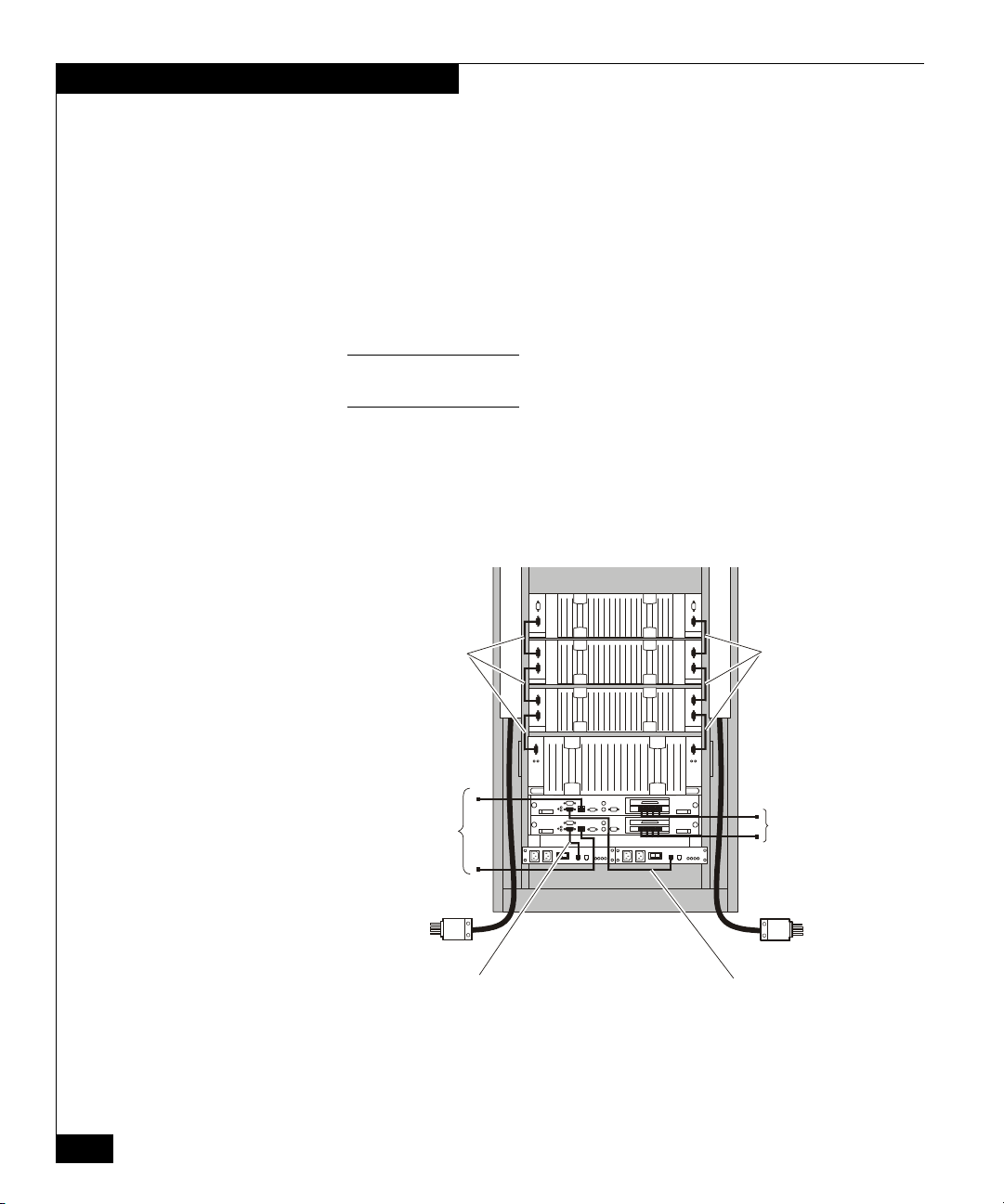
Verify Cabling 9. Refer to the IP4700 Quick Start Guide and the IP4700 Installation
7. Ensure that the DPE is configured with 10 disks of the same size
and speed. Supported disks and configurations are listed on
page 3 of this document.
8. Move disks 0, 1, and 2 in the DPE to positions in slots 3-9. For
example, exchange disk 0 with disk 9, disk 1 with disk 8, and disk
2 with disk 7.
If necessary, refer to chapter 3 in the IP4700 Installation and Service
Guide for instructions on removing and installing disk drives.
Permanent FC4700 information in “system” disks 0-2 will prevent IP4700
powerup if the disks remain in (or are returned to) DPE slots 0, 1, or 2.
and Service Guide to ensure that the system is properly cabled for
the IP4700. Figure 1 shows a sample configuration, with three
DAEs above the IP4700 DPE.
Fibre Channel Fibre Channel
Management
LAN
LAN
Rear of cabinet
Storage processor A
to standby power supply A
interface
Figure 1 Example IP4700 Configuration - Three DAEs
6
Fibre Channel FC4700 Array to IP4700 File Server Conversion Guide
Storage processor B
to standb
interface
power suppl
EMC1485
Page 7

Loading IP4700 Software
The steps in this section guide you through the firmware/software
loading process. They begin with verifying and, if necessary, flashing
new firmware to each storage processor. You must follow the remaining
steps in the exact order listed. They describe how to load an IP4700
software image from the hard drive in your conversion kit (“seed
disk”) to the system.
Locate the IP4700 seed disk (P/N 005047310) in your conversion kit and have
it available before you begin this procedure.
1. Connect a Windows® console to SP A through the serial port, as
shown in Step 3 of the IP4700 Quick Start Guide.
2. Start a HyperTerminal session.
3. If necessary, turn on ac cabinet power to the side that powers SPS
A, then to the side that powers SPS B. Turn the SPS A power
switch to the on position, then do the same for SPS B.
Since the current 0, 1, and 2 drives do not contain a loadable
image, the autoboot will fail. The following screen displays the
error.
Loading IP4700 Software
EndTime: 3/16/2001 14:27:06 DiagName: PROM Kernel
AutoBoot Enabled! ByPass Auto Booting ([N], Y)? [0]
Starting loop initialization
Loop is initialized.
No valid image exists.
Unable to load image.
ErrorTime: 3/16/2001 14:27:16 ErrorCode: 1012
ErrorDesc: Autoboot fails loading flare image from fibre disks.
EndError
FS > _
Wait for the system to display the FS > prompt before
continuing with Step 4.
Fibre Channel FC4700 Array to IP4700 File Server Conversion Guide
7
Page 8

Loading IP4700 Software
If necessary, refer to chapter 3 in the IP4700 Installation and Service
Guide for instructions on removing and installing disk drives.
4. Remove the disk drive installed in DPE slot 0 (the leftmost slot)
and set it aside.
Note that the disks in DPE slots 0-2 should NOT be the 0-2 disks in the
previous FC4700 configuration (per step 8 in the preceding section,
“Converting the Hardware”).
5. Install the seed disk (P/N 005047310) into DPE slot 0. Wait until
the LED is on solid before continuing with the next step.
6. At the FS > prompt, type finit and then press <Enter>.
FS > finit
↵
Starting loop initialization
Loop is initialized.
7. At the FS > prompt, type showrev and then press <Enter>.
Minimum revisions of PROM and BIOS are displayed below.
FS > showrev ↵
Prom Version: 03:05:97
Bios Version: 4.06 v01.22
If the PROM and BIOS versions are at or above the minimum
listed above, proceed to step 8.
If the PROM and/or BIOS versions are below the minimum listed
above, perform the following:
FS> engrmode on
↵
FS> dsktofl 0 ↵ (to flash firmware from disk 0 to the SP)
FS> dsktofl b 0
↵ (to flash BIOS from disk 0 to the SP)
FS> engrmode off
↵
8. Move the serial cable to SP B.
8
Fibre Channel FC4700 Array to IP4700 File Server Conversion Guide
Page 9

Loading IP4700 Software
9. Repeat step 7 for the second SP, upgrading PROM or BIOS if
necessary.
If you did not upgrade PROM or BIOS in the preceding steps,
continue with step 10.
If you did upgrade PROM or BIOS on either storage processor,
you need to power cycle the system to complete the firmware
upgrade:
a. Remove the seed disk and replace it with the disk drive you
removed previously in Step 4.
b. Move the serial cable to SP A.
c. power cycle the DPE as described in Chapter 2 of the IP4700
Installation and Service Guide:
• Turn the power switches on the Standby Power Supplies to
the off position.
• Wait for all LED activity on the DPE to cease, and for the
fans to stop running.
• Turn the power switch on SPS A to the on position, then do
the same for SPS B.
The autoboot will fail again. Wait for the system to display the
FS > prompt before continuing with Step d.
d. Remove the disk drive installed in DPE slot 0 and set it aside.
e. Install the seed disk (P/N 005047310) into DPE slot 0.
10. At the FS > prompt, type finit and then press <Enter>.
FS > finit
↵
Starting loop initialization
Loop is initialized.
!
CAUTION
Failure to copy the image in the correct sequence will result in
an unrecoverable condition.
The conversion hard disk that contains your IP4700 software is
not write-protected. Take care to enter the dsktodsk commands
correctly and avoid overwriting the seed disk.
Fibre Channel FC4700 Array to IP4700 File Server Conversion Guide
9
Page 10

Loading IP4700 Software
11. At the FS > prompt, type dsktodsk 0,1 and then press <Enter>.
This copies the image from the seed disk (0) to disk 1 in
approximately ten seconds.
FS > dsktodsk 0,1
↵
Installing image from disk 0 to disk 1.......
.............................................
.............................................
............................................
12. At the FS > prompt, type dsktodsk 0,2 and then press <Enter>.
This copies the image from the seed disk (0) to disk 2 in
approximately ten seconds.
FS > dsktodsk 0,2 ↵
Installing image from disk 0 to disk 2.......
.............................................
.............................................
............................................
13. Remove the seed disk from DPE slot 0, and replace it with the
drive you removed in step 4.
14. Wait for the disk LEDs to stop flashing and remain on solid,
indicating that the disk is up and ready.
15. At the FS > prompt, type finit and then press <Enter>.
10
FS > finit ↵
Starting loop initialization
Loop is initialized.
16. At the FS > prompt, type dsktodsk 2,0 and then press <Enter>.
This copies the image from disk 2 to disk 0 in approximately ten
seconds.
Fibre Channel FC4700 Array to IP4700 File Server Conversion Guide
Page 11

Loading IP4700 Software
FS > dsktodsk 2,0
↵
Installing image from disk 2 to disk 0.......
.............................................
.............................................
............................................
Note: If you see the error message: disk 2 not on the loop, ensure
that the disk 2 LED is on solid and repeat Step 15 before trying again.
To finish the FC4700-to-IP4700 conversion, you must clear (zero) all
the disks in the system of previous data, and complete the IP4700
factory initialization process. The next section in this guide describes
the zero disk and factory initialization procedures.
Fibre Channel FC4700 Array to IP4700 File Server Conversion Guide
11
Page 12

Factory Initialization
Factory Initialization
Factory initialization is a process that all new IP4700 systems
experience prior to shipment. The process begins by clearing all data
from the DPE and DAE(s) in the IP4700 system, and then binds the
disks into file server volumes. You must follow this same process to
complete the FC4700-to-IP4700 conversion, and leave your system
ready for the network initialization process common to all IP4700 file
servers.
1. Locate the DPE serial number label on the back of the unit. Copy
the number here – __________________________
.
You will need it later in the procedure.
2. Verify that the yellow SPS LEDs are off and the green LEDs are
either on or flashing.
3. power cycle the DPE as described in Chapter 2 of the IP4700
Installation and Service Guide:
a. Turn the power switches on the Standby Power Supplies to the
off position.
12
b. Wait for all LED activity on the DPE to cease, and for the fans
to stop running. (Note that if the SPS was in the ready state it
will hold power for 90 seconds.)
c. Wait an additional 30 seconds.
d. Turn on the power switch on SPS A, then do the same for SPS
B.
4. Enter ^V (CTRL-V) immediately when the system displays the
IP4700 banner.
Fibre Channel FC4700 Array to IP4700 File Server Conversion Guide
Page 13

Factory Initialization
@
@
@
@@@@@@
@@
@@
@@
@@
@@
@@@@@@
@@@@@
@@ @@
@@ @@
@@ @@
@@@@@
@@
@@
@@@
@@@
@@@
@@@
@@@@@@@
@@
@@
@@@@@@
@@ @@
@@
@@
@@
@@
@@
@@
@@
@@ @@
@@ @@
@@ @@
@@
@@
@@
@@
@@ @
@@ @
@@ @
@@
@@
Starting SP Components. Please Wait....
Once the IP4700 banner is displayed, you have a maximum of 60 seconds to
enter ^V.
Entering ^V should cause the following to display immediately:
================================================
==== Enabling Factory Initialization Startup ====
================================================
Raid System Started Successfully......
If Enabling Factory Initialization Startup does not
display, one of the following may occur:
– The system reboots and comes up to the IP4700 banner.
Starting SP Components. Please Wait.....
Raid System Started Successfully........
(the display will recycle)
– The system hangs.
In either case manually reset the SPs. Reset SP A first, then SP B.
You can reset the SPs by power cycling the system, as described in
step 3 on page 12.
5. Enter ^V at the IP4700 banner.
Fibre Channel FC4700 Array to IP4700 File Server Conversion Guide
13
Page 14

Factory Initialization
@
@
@
@@@@@@
@@
@@
@@
@@
@@
@@@@@@
@@@@@
@@ @@
@@ @@
@@ @@
@@@@@
@@
@@
@@@
@@@
@@@
@@@
@@@@@@@
Starting SP Components. Please Wait.....[].
Raid System Started Successfully.....
6. When you see the Boot Console menu, type 2 at the
Enter Number of Your Choice: field, and then press
<Enter> to reach the fcli command line.
Boot Console
1.Perform Factory Initialization
2. Access FCLI
3. Recover Administrative State
4. Recreate System Volumes
5. Check File System on Volumes
@@
@@
@@@@@@
@@ @@
@@
@@
@@
@@
@@
@@
@@
@@ @@
@@ @@
@@ @@
@@
@@
@@
@@
@@ @
@@ @
@@ @
@@
@@
14
6. Authorized Service Personnel Only
Q. Quit Boot Console.
Enter Number Of Your Choice: 2
↵
FCLI Passthru Command Line. Type menu to return to menu interface.
fcli >
Fibre Channel FC4700 Array to IP4700 File Server Conversion Guide
Page 15

Factory Initialization
Verify System Status 7. At the fcli > prompt, type ls and then press <Enter>.
fcli >ls
↵
ls: There are no currently bound units
03/29/2001 10:30:14 GMT
fcli >
Note: If the display indicates bound LUNs, you have “stale data” on disk 0.
Refer to the previous section, “Loading IP4700 Software,” for instructions as
you perform the following:
• Exchange disk 0 with another drive.
• (Make certain the new drive has never been in position 0, 1, or 2.)
• Power cycle the DPE.
• Copy the system image from disk 2 to disk 0.
• Begin again at Step 2 in this section.
8. At the fcli> prompt, type spstat and then press <Enter> as
shown on page 16.
Fibre Channel FC4700 Array to IP4700 File Server Conversion Guide
15
Page 16

Factory Initialization
FCLI Passthru Command Line. Type menu to return to menu interface.
fcli > spstat
↵
SP A LOOP ID 0x7e (126.)
Microcode Revision: “@(#) IP4700 R1.1 p8.4
Statistics Logging: DISABLED PEER SP: PRESENT
Disk Write Caching: DISABLED R3 Write Buffering: DISABLED
WRITE CACHE: DISABLED READ CACHE: DISABLED
RAID OPTIMIZED: Mixed LUNs SP TYPE: IP4700
LUN REMAPPING: DISABLED
A: DP 00TOTAL 0000 DIRTY 0000
B: TOTAL 0000
U: DP 00TOTAL 0000
Requests Complete: 19
SPS A: NR
SPS B: NR
Press any key to continue....
↵
9. Examine the SPSTAT information carefully. Verify the following:
– the PEER SP is PRESENT
– the SPS units are in one of the following states: TE, NR, or OK.
10. Press <Enter> to go to the next screen
slot: 0 1 2 3 4 5 6 7 8 9 PSA PSB FAN
DPE1-state: UNB UNB UNB UNB UNB UNB UNB UNB UNB UNB OK OK OK OK
Unit/Group : ** ** ** ** ** ** ** ** ** **
DAE1-state: UNB UNB UNB UNB UNB UNB UNB UNB UNB UNB
Unit/Group : ** ** ** ** ** ** ** ** ** **
03/16/2001 15:35:08 gmt
fcli> _
16
Fibre Channel FC4700 Array to IP4700 File Server Conversion Guide
Page 17

Factory Initialization
11. On the second screen of SPSTAT information, verify the
following:
– The system sees all the disk drives and they are unbound.
– The system sees all power supplies and fan modules and they
are OK.
NOTE: If you do not see the DAEs and disks you expect, verify that the
Enclosure IDs and cabling are correct. If you need to change them, then you
must reset both SPs. You can reset the SPs by powercycling the system, as
described in step 3 on page 12.
12. At the fcli> prompt, type clearlog and then press <Enter>.
Zero Disk to Clear
Drives
fcli > clearlog
↵
13. At the fcli> prompt, type zd all and then press <Enter>.
fcli> zd all ↵
Status recv’d opcode 0x8a status 0x0
The disk LEDs flash randomly on each shelf.
The zero disk function you just implemented enables the fast bind
feature, and takes approximately 15 minutes. Go to step 14 now
while the command executes.
Fibre Channel FC4700 Array to IP4700 File Server Conversion Guide
17
Page 18

Factory Initialization
14. At the fcli> prompt, t ype spstat and then press <Enter>. Verify
that a ZER has replaced the UNB.
fcli > spstat
↵
SP A LOOP ID 0x7e (126.)
Microcode Revision: “@(#) IP4700 R1.1 p8.4
Statistics Logging: DISABLED PEER SP: PRESENT
Disk Write Caching: DISABLED R3 Write Buffering: DISABLED
WRITE CACHE: DISABLED READ CACHE: DISABLED
RAID OPTIMIZED: Mixed LUNs SP TYPE: IP4700
LUN REMAPPING: DISABLED
A: DP 00TOTAL 0000 DIRTY 0000
B: TOTAL 0000
U: DP 00TOTAL 0000
Requests Complete: 19
SPS A: OK
SPS B: OK
Press any key to continue....
↵
slot: 0 1 2 3 4 5 6 7 8 9 PSA PSB FAN
DPE1-state: ZER ZER ZER ZER ZER ZER ZER ZER ZER ZER OK OK OK OK
Unit/Group : ** ** ** ** ** ** ** ** ** **
DAE1-state: ZER ZER ZER ZER ZER ZER ZER ZER ZER ZER
Unit/Group : ** ** ** ** ** ** ** ** ** **
18
15. At the fcli> prompt, type getlog and then press <Enter>. Verify
that the log reports a Factory Zero Started for each disk
drive.
Fibre Channel FC4700 Array to IP4700 File Server Conversion Guide
Page 19

Factory Initialization
fcli> getlog ↵
Event Date CRU Event (Message) Extended Status
1. 03/16/01 15:48:16 0_0 0x6fa (Factory Zero Started) 0x00
2. 03/16/01 15:48:16 0_1 0x6fa (Factory Zero Started) 0x00
3. 03/16/01 15:48:16 0_2 0x6fa (Factory Zero Started) 0x00
4. 03/16/01 15:48:16 0_3 0x6fa (Factory Zero Started) 0x00
5. 03/16/01 15:48:16 0_4 0x6fa (Factory Zero Started) 0x00
6. 03/16/01 15:48:16 0_5 0x6fa (Factory Zero Started) 0x00
7. 03/16/01 15:48:16 0_6 0x6fa (Factory Zero Started) 0x00
8. 03/16/01 15:48:16 0_7 0x6fa (Factory Zero Started) 0x00
9. 03/16/01 15:48:16 0_8 0x6fa (Factory Zero Started) 0x00
10. 03/16/01 15:48:16 0_9 0x6fa (Factory Zero Started) 0x00
11. 03/16/01 15:48:16 1_0 0x6fa (Factory Zero Started) 0x00
12. 03/16/01 15:48:16 1_1 0x6fa (Factory Zero Started) 0x00
13. 03/16/01 15:48:16 1_2 0x6fa (Factory Zero Started) 0x00
14. 03/16/01 15:48:16 1_3 0x6fa (Factory Zero Started) 0x00
15. 03/16/01 15:48:16 1_4 0x6fa (Factory Zero Started) 0x00
16. 03/16/01 15:48:16 1_5 0x6fa (Factory Zero Started) 0x00
17. 03/16/01 15:48:16 1_6 0x6fa (Factory Zero Started) 0x00
18. 03/16/01 15:48:16 1_7 0x6fa (Factory Zero Started) 0x00
19. 03/16/01 15:48:16 1_8 0x6fa (Factory Zero Started) 0x00
Press any key to continue... (or “q” to Quit) ↵
16. At the fcli> prompt, type clearlog and then press <Enter>.
fcli > clearlog ↵
17. Once ALL the disk LEDs have stopped flashing, type getlog at
the fcli> prompt and then press <Enter>. Verify that all disks
report successful completion of the zero disk operation.
NOTE: If disk drives in a DAE do not report starting factory zero, verify
that both fibre loop cables are connected, as required by the internal code.
Fibre Channel FC4700 Array to IP4700 File Server Conversion Guide
19
Page 20

Factory Initialization
fcli> getlog
↵
Event Date CRU Event (Message) Extended Status
0. 03/16/01 15:48:16 1_9 0x6fa (Factory Zero Started) 0x00
1. 03/16/01 15:57:18 0_9 0x6fc (Factory Zero Completed) 0x00
2. 03/16/01 15:57:18 1_2 0x6fc (Factory Zero Completed) 0x00
3. 03/16/01 15:57:19 1_1 0x6fc (Factory Zero Completed) 0x00
4. 03/16/01 15:57:57 1_0 0x6fc (Factory Zero Completed) 0x00
5. 03/16/01 15:57:57 1_5 0x6fc (Factory Zero Completed) 0x00
6. 03/16/01 15:57:57 1_3 0x6fc (Factory Zero Completed) 0x00
7. 03/16/01 15:57:57 1_9 0x6fc (Factory Zero Completed) 0x00
8. 03/16/01 15:57:57 1_4 0x6fc (Factory Zero Completed) 0x00
9. 03/16/01 15:57:57 1_8 0x6fc (Factory Zero Completed) 0x00
10. 03/16/01 15:57:57 1_7 0x6fc (Factory Zero Completed) 0x00
11. 03/16/01 15:58:01 1_6 0x6fc (Factory Zero Completed) 0x00
12. 03/16/01 16:02:40 0_5 0x6fc (Factory Zero Completed) 0x00
13. 03/16/01 16:02:40 0_6 0x6fc (Factory Zero Completed) 0x00
14. 03/16/01 16:02:40 0_3 0x6fc (Factory Zero Completed) 0x00
15. 03/16/01 16:02:40 0_4 0x6fc (Factory Zero Completed) 0x00
16. 03/16/01 16:02:41 0_7 0x6fc (Factory Zero Completed) 0x00
17. 03/16/01 16:02:41 0_8 0x6fc (Factory Zero Completed) 0x00
18. 03/16/01 16:03:34 0_1 0x6fc (Factory Zero Completed) 0x00
19. 03/16/01 16:03:34 1_8 0x6fc (Factory Zero Completed) 0x00
Press any key to continue... (or “q” to Quit) ↵
18. At the fcli> prompt, type clearlog and then press <Enter>.
fcli > clearlog ↵
20
Fibre Channel FC4700 Array to IP4700 File Server Conversion Guide
Page 21

Factory Initialization
@
@
@
Load DPE Chassis
Serial Number
19. At the fcli> prompt, type setser serial number and then press
<Enter>.
In the serial number field, enter the last 12 characters, beginning
with F, of the DPE Chassis Serial Number you recorded on
page 12.
fcli> setser F20004701426
↵
Warning: Changing of the System Serial Number
will cause an immediate reboot and a new Fibre
Channel WWN to be created. This command will
fail if the write cache is not in the disable
state and if any I/O is outstanding.
Continue [y/n]
y
20. Enter y to reboot the system.
Although rebooting takes a few minutes, be prepared to interrupt the
autoboot process at the IP4700 banner.
21. Enter ^V (CTRL-V) immediately when the system displays the
IP4700 banner.
@@@@@@
@@
@@
@@
@@
@@
@@@@@@
@@@@@
@@ @@
@@ @@
@@ @@
@@@@@
@@
@@
@@@
@@@
@@@
@@@
@@@@@@@
Starting SP Components. Please Wait....
22. When the Boot Console menu displays, type 2 at the
Enter Number of Your Choice: field, and then press
<Enter> to reach the fcli command line.
Fibre Channel FC4700 Array to IP4700 File Server Conversion Guide
@@
@@
@@@@@@
@@ @@
@@
@@
@@
@@
@@
@@
@@
@@ @@
@@ @@
@@ @@
@@
@@
@@
@@
@@ @
@@ @
@@ @
@@
@@
21
Page 22

Factory Initialization
Boot Console
1. Perform Factory Initialization
2. Access FCLI
3. Recover Administrative State
4. Recreate System Volumes
5. Check File System on Volumes
6. Authorized Service Personnel Only
Q. Quit Boot Console.
Enter Number Of Your Choice: 2
↵
FCLI Passthru Command Line. Type menu to return to menu interface.
fcli >
23. At the fcli > prompt, type setser and then press <Enter>.
fcli> setser ↵
Current serial number is: f20004701426
24. Verify that you entered the serial number accurately. If the serial
number is incorrect, repeat Steps 19 through 23.
25. At the fcli > prompt, type clearlog and then press <Enter>.
26. At the fcli > prompt, type menu and then press <Enter>.
The system exits fcli mode and displays the Boot Console menu.
22
Fibre Channel FC4700 Array to IP4700 File Server Conversion Guide
Page 23

Factory Initialization
fcli> menu
Perform the Factory
Initialization
↵
Boot Console
1. Perform Factory Initialization
2. Access FCLI
3. Recover Administrative State
4. Recreate System Volumes
5. Check File System on Volumes
6. Authorized Service Personnel Only
Q. Quit Boot Console.
Enter Number Of Your Choice:
27. Perform the Factory Initialization process:
a. At the Enter Number of Your Choice: prompt, type
1 and then press <Enter>.
b. When asked to confirm, type y and then press <Enter>.
The initialization process should take 5 minutes or less to
complete.
Boot Console
1. Perform Factory Initialization
2. Access FCLI
3. Recover Administrative State
4. Recreate System Volumes
5. Check File System on Volumes
6. Authorized Service Personnel Only
Q. Quit Boot Console.
Enter Number Of Your Choice: 1
Are you sure you want to perform Factory Initialization?
All volumes and data will be deleted (y/n): y_
Fibre Channel FC4700 Array to IP4700 File Server Conversion Guide
↵
23
Page 24

Factory Initialization
28. When the initialization completes, press <Enter> to reboot the
system.
Removing Raid Groups...
Creating System Volumes...
Command “setfkey -id 80000002 -q c -n “num-encl”” NOT found
03/16/2001 16:12:31 GMT
fcli>
Waiting For System Volumes Bind...
Initializing System Volumes...
Extracting Web and Help Files...
Creating Volumes A0 and B0...
FACTORY INITIALIZATION COMPLETED SUCCESSFULLY
Hit return to reboot the system
↵
Reboot time is approximately 5 minutes. When the system
finishes booting, it displays the IP4700 banner and a request to
Press Enter to continue.
24
Fibre Channel FC4700 Array to IP4700 File Server Conversion Guide
Page 25

@
@
@
Starting SP Components. Please Wait.
Raid System Started Successfully....
Volume Manager Started Successfully.
Root File System Started Successfully...
Factory Initialization
Perform the Site
Initialization
@@@@@@
@@
@@
@@
@@
@@
@@@@@@
@@@@@
@@ @@
@@ @@
@@ @@
@@@@@
@@
@@
@@@
@@@
@@@
@@@
@@@@@@@
@@
@@
@@@@@@
@@ @@
@@
@@
@@
@@
@@
@@
@@
@@ @@
@@ @@
@@ @@
@@
@@
@@
@@
@@ @
@@ @
@@ @
@@
@@
Press Enter to continue...
The conversion from an FC4700 to an IP4700 is now complete.
Next you must launch the IP4700 Initialization Wizard (sometimes
called the Setup Wizard). The wizard guides you through the
standard IP4700 network initialization.
Before you start, make sure you have gathered the necessary network
information and filled out the work sheets in Step 1 of the IP4700 Quick Start
Guide.
29. To start the IP4700 Initialization Wizard via the serial port, press
<Enter> at the IP4700 banner display.
The wizard displays a greeting message and asks you to continue.
Fibre Channel FC4700 Array to IP4700 File Server Conversion Guide
25
Page 26

Factory Initialization
System Installation 30. To install the new system, follow the instructions in the IP4700
Setup guides you through the network initialization
of your IP4700.
If at any time you wish to abort a step, press q.
Press Enter to continue..._
Quick Start Guide, the on-line wizard instructions, and the IP4700
Release Notes for your software revision. They will help you
ensure that your license keys and other options are installed
correctly.
You may need to update the IP4700 software to the latest release.
To determine whether you need to update it and how to receive
the latest software, contact your authorized IP4700 service
provider.
Copyright © EMC Corporation 2001. All rights reserved
Revision 00, May 2001
No part of this publication may be reproduced or distributed in any form or by any means, or stored in a
database or retrieval system, without the prior written consent of EMC Corporation.
The information contained in this document is subject to change without notice. EMC Corporation assumes
no responsibility for any errors that may appear.
EMC Corporation makes no warranties, expressed or implied, by operation of law or otherwise, relating to
this document, the products or the computer software programs described herein. EMC CORPORATION
DISCLAIMS ALL IMPLIED WARRANTIES OF MERCHANTIBILITY AND FITNESS FOR A PARTICULAR
PURPOSE. In no event shall EMC Corporation be liable for (a) incidental, indirect, special, or consequential
damages or (b) any damages whatsoever resulting from the loss of use, data or profits, arising out of this
document, even if advised of the possibility of such damages.
Trademark Information
EMC2, EMC, CLARalert, and Navisphere are registered trademarks of EMC Corporation.
All other trademarks mentioned herein are the property of their respective owners.
26
Fibre Channel FC4700 Array to IP4700 File Server Conversion Guide
 Loading...