

Embux ICM-3011 Series User Manual

ICM-3011 Series
3.5’’ SBC with NXP i.MX6 Processor
ARM ® Cortex A9 Architecture
User Manual
Ver. 1st
1

Copyright
Copyright © 2015 EMBUX Technology Co., Ltd., All rights reserved.
EMBUX Technology Co., Ltd. reserves the right to make improvements in the
products described in this manual at any time without notice. No part of this
manual may be reproduced, copied, translated or transmitted in any form or by
any means without prior written permission of EMBUX Technology Co., Ltd.
Trademark
The EMBUX logo is a registered trademark of EMBUX Technology Co., Ltd.
All other trademarks or registered marks in this manual belong to their respective
manufacturers.
Disclaimer
Information in this document is subject to change without notice and does not
represent a commitment on the part of EMBUX.
EMBUX provides this document as is, without warranty of any kind, either
expressed or implied, including, but not limited to, its particular purpose. EMBUX
reserves the right to make improvements and/or changes to this manual, or to
the products and/or the programs described in this manual, at any time.
Information provided in this manual is intended to be accurate and reliable.
However, EMBUX Technology Co., Ltd. assumes no responsibility for its use, nor
for any infringements of the rights of third parties, which may result from its use.
This product might include unintentional technical or typographical errors.
Changes are periodically made to the information herein to correct such errors,
and these changes are incorporated into new editions of the publication.
2

Declaration of Conformity
FCC Class A
Note: this device has been tested and found to comply with the limits for a Class
A digital device, pursuant to part 15 of the FCC Rules. These limits are designed
to provide reasonable protection against harmful interference in a residential
installation. This device generates, uses and can radiate radio frequency energy
and, if not installed and used in accordance with the instructions, may cause
harmful interference to radio communication. However, there is no guarantee
that interference will not occur in a particular in a particular installation. If this
device does cause harmful interference to radio or television reception, which
can be determined by turning the device off and on, the user is encouraged to try
to correct the interference by one or more of following measures:
Reorient or relocate the receiving antenna
Increase the separation between the device and receiver
Connect the device into an outlet on a circuit different from that to which
receiver is connected
Consult the dealer or an experienced radio/TV technician for help
CE Marking
This device has passed the CE test for environmental specifications when shielded
cables are used for external wiring. We recommend the use of shielded cables.
This device has passed the CE test for environmental specifications. Test
conditions for passing included the equipment being operated within an
industrial enclosure. In order to protect the product from being damaged by ESD
(Electrostatic Discharge) and EMI leakage, we strongly recommend the use of CEcompliant industrial enclosure products.
3

Document Amendment History
Revision
Date
Remark
1st
Jan 2016
Initial released
2nd
Mar 2016
Hardware User Guide modified
3rd
Mar 2016
Software User Guide & System Recovery
modified
4

Table of Contents
1. Product Overview .................................................................................................. 8
1.1. Introduction ........................................................................................... 8
1.2. Specification ........................................................................................... 8
1.3. Block Diagram ...................................................................................... 10
2. Hardware User Guide ........................................................................................... 12
2.1. Dip Switch Setting and Connector Locations ....................................... 12
2.2. DIP Switch Setting ................................................................................ 13
2.2.1. Booting from eMMC (Default) ..................................................... 13
2.2.2. Upgrade latest image to eMMC (PG) ........................................... 13
2.2.3. Booting from SD ........................................................................... 13
2.3. Connector ............................................................................................. 14
2.3.1. Connector List .............................................................................. 14
2.3.2. Connector Setting ........................................................................ 15
2.3.2.1. JAUDIO ................................................................................. 15
2.3.2.2. JBLK ...................................................................................... 15
2.3.2.3. JCOM1 .................................................................................. 15
2.3.2.4. JCOM4 .................................................................................. 16
2.3.2.5. JCOMA .................................................................................. 16
2.3.2.6. JCOMB .................................................................................. 16
2.3.2.7. JCOMC .................................................................................. 16
2.3.2.8. JCOMD ................................................................................. 17
2.3.2.9. JDC-IN ................................................................................... 17
2.3.2.10. JEMBUX (MCU) .................................................................. 17
2.3.2.11. JFP ...................................................................................... 18
2.3.2.12. JGPIO (i.MX6) ..................................................................... 18
2.3.2.13. JI2C ..................................................................................... 18
2.3.2.14. JLVDS1 ................................................................................ 18
2.3.2.15. JLVDS2 ................................................................................ 19
2.3.2.16. JMISC .................................................................................. 19
2.3.2.17. JRS-485 ............................................................................... 19
2.3.2.18. JSPI ..................................................................................... 19
2.3.2.19. JSPKR_L .............................................................................. 20
2.3.2.20. JSPKR_R .............................................................................. 20
2.3.2.21. JUSB ................................................................................... 20
2.3.2.22. RS-485 ................................................................................ 20
2.4. Mechanical Drawing ............................................................................. 21
5

3. Software User Guide ............................................................................................ 23
3.1. Introduction ......................................................................................... 23
3.2. Working with the ICM-3011 Board and Platform ................................ 23
3.2.1. Board hardware ........................................................................... 23
3.2.2. Board images................................................................................ 23
3.2.3. Downloading board images ......................................................... 24
3.2.4. Booting ......................................................................................... 26
3.3. Applications and Testing ...................................................................... 27
3.3.1. Ethernet Test ................................................................................ 27
3.3.2. USB (TBD) ..................................................................................... 27
3.3.3. SD ................................................................................................. 28
3.3.4. I2C ................................................................................................ 28
4. System Recovery .................................................................................................. 30
4.1. Download the SD image ....................................................................... 30
4.2. Write an SD/MMC Card using Linux (Ubuntu) ..................................... 30
4.3. Write an SD/MMC Card using Windows .............................................. 31
4.3.1. Introduction ................................................................................. 31
4.3.2. Preparations ................................................................................. 31
4.3.3. Create SD-Card ............................................................................. 31
4.4. Write an SD/MMC Card using MAC OS X ............................................. 32
4.4.1. Graphical interface ....................................................................... 32
4.4.2. Command line .............................................................................. 32
4.4.3. Alternative method ...................................................................... 33
6

Product Overview
This chapter provides background information of ICM-3011.
Chapter 1
7
1. Product Overview
System Hardware - CPU
CPU
NXP i.MX6 Cortex-A9 DualLite
Memory
Technology
DDR3-800
Capacity
Onboard 2GB
Flash
4GB eMMC NAND Flash
8MB NOR Flash
Graphic
HDMI
1 x HDMI connector
LVDS
2 x 18/24 bit LVDS header (2x10 1.25mm Hirose DF13 series
compatible)
Watchdog Timer
1~256 level (0.5 second / level)
RTC
EPSON RX8010SJ RTC chip
Indicator
LED
1 x configurable indicator controlled by i.MX6
I/O
LAN
1 x Micrel KSZ9031RNX Gigabit Ethernet
USB
4 x USB 2.0
USB OTG
1 x USB OTG (Micro USB Type AB connector)
Serial Port
4 x RS-232 (8-wire) header
2 x RS-232 (4-wire) header
1 x RS-485 (3.5mm terminal block)
1 x RS-485 (miscellaneous header)
CAN
2 x CAN (miscellaneous header)
GPIO
8 x GPIO header
1.1. Introduction
ICM-3011 is a 3.5’’ SBC (Single Board Computer) with ARM Cortex-A9 NXP i.MX6
DualLite 1GHz processor and ARM Cortex™-M0 32-bit RISC core (MCU). The ICM-3011
supports 2GB DDR3, 8MB NOR Flash and 4GB eMMC NAND Flash, 2 x LVDS, 1 x HDMI
display, 1 x Gigabit LAN with IEEE 1588, 4 x USB 2.0, 1 x USB OTG, 4 x RS-232(8-wire),
2 x RS-232(4 wire), 2 x RS-485, 2 x CAN, 1 x SDIO and 1 x SD.
Integrated unique dual hardware structure and RTOS (Real Time Operating
System) design, ICM-3011 has outstanding crash free protection on both hardware
reliability and software stability. With the special features, ICM-3011 is a perfect device
to meet customers’ versatile needs.
The ICM-3011 focuses on industrial application and it provides high performance
and low power consumption from its ARM ® Cortex A9 architecture which is ready-torun, compact, and easy-to-expand. With flexible I/O interfaces and complete hardware
and software solutions, ICM-3011 is a fast time-to-market platform for customers to
develop their applications and products easily.
1.2. Specification
8
Button
1 x power-on header
1 x reset button
SD socket
1 x SD socket
SDIO socket
1 x SDIO socket
System Hardware - MCU
(For EMBUX system product design only)
MCU
STM32F051R8T6
Memory
Flash
8MB NOR Flash
I/O
EMBUX X Port
1 x EMBUX X Port (miscellaneous header-JMISC)
I2C
1 x I2C interface (2x10 1.25mm Hirose DF13 series compatible, shared
with SPI and GPIO) for Mainboard MCU to accessory (i.e. OLED module)
connection purpose
SPI
1 x SPI interface (2x10 1.25mm Hirose DF13 series compatible, shared
with I2C and GPIO) for Mainboard MCU to accessory (i.e. OLED module)
connection purpose
GPIO
7-bit GPIO (2x10 1.25mm Hirose DF13 series compatible, shared with
SPI and I2C) for Mainboard MCU to accessory (i.e. OLED module)
connection purpose
2-bit GPIO (5x2 header, pitch 2.0mm-JFP)
System Software
Operating System
yocto
Daisy 1.6.2
android
Lollipop 5.0.2
WEC
Windows Embedded Compact 7
Environment & Mechanism
Temperature
Operating
temperature
-20~70° C
Humidity
Operating
humidity
5%~95% Relative Humidity, non-condensing
Mechanism
Dimension
3.5" SBC (146mm X 102mm)
Power
DC-input
12V (10.8V~13.2V)
Control
Power on by DC attached or via power button
Consumption
~3.5W
9
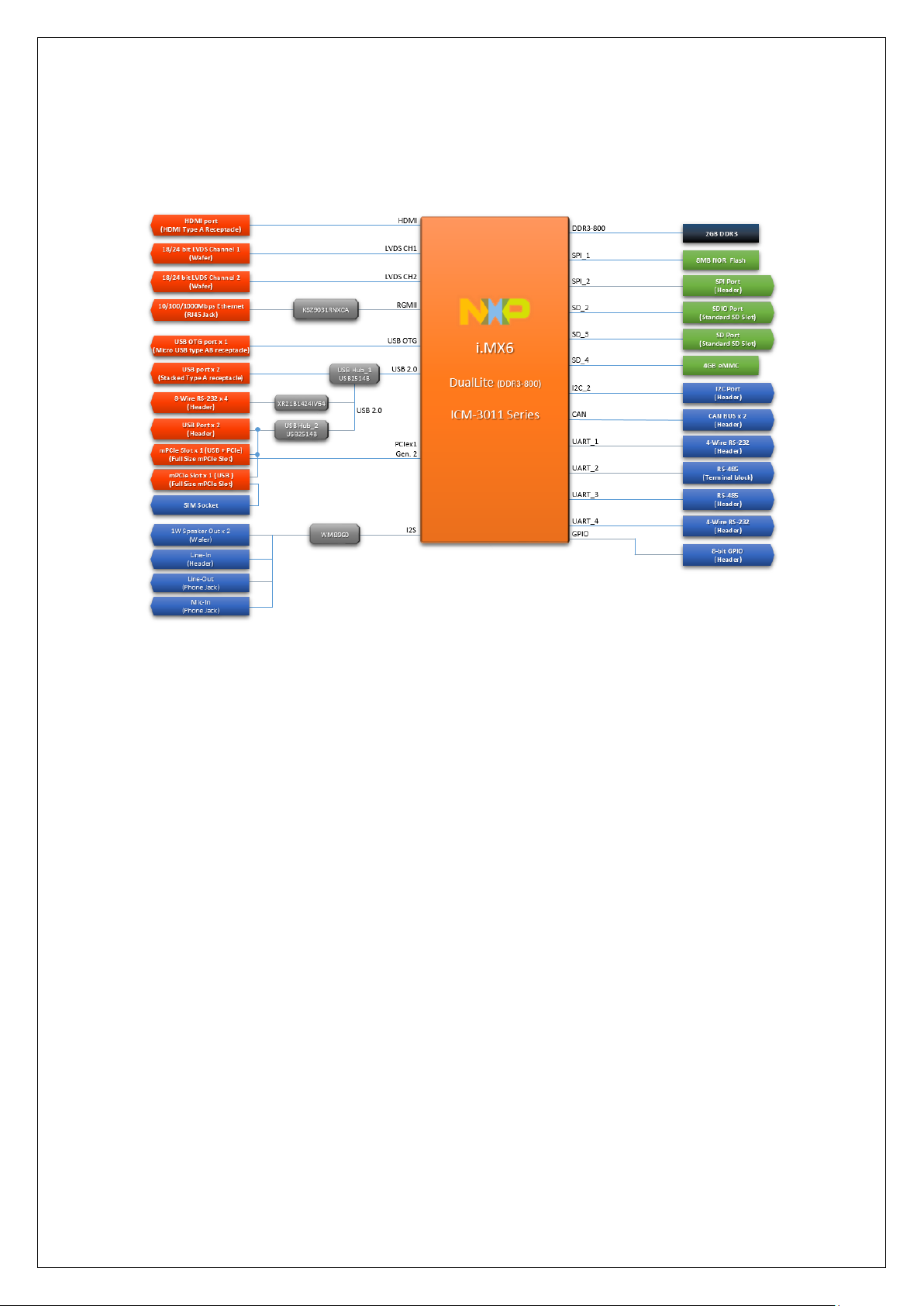
1.3. Block Diagram
10

Hardware User Guide
This chapter introduces the startup procedures of ICM-3011, device
integration. It also introduces the setting of switches, indicators and
also shows the mechanical drawings. Be sure to read all safety
precautions before you begin installation procedure.
Chapter 2
11
 Loading...