

Page 1
1
ICM-2010 Series
2.5’’ SBC with Freescale i.MX6 Processor
ARM ® Cortex A9 Architecture
User Manual
Ver. 1st
Page 2

2
Copyright
Copyright © 2015 EMBUX Technology Co., Ltd., All rights reserved.
EMBUX Technology Co., Ltd. reserves the right to make improvements in the
products described in this manual at any time without notice. No part of this
manual may be reproduced, copied, translated or transmitted in any form or by
any means without prior written permission of EMBUX Technology Co., Ltd.
Trademark
The EMBUX logo is a registered trademark of EMBUX Technology Co., Ltd.
All other trademarks or registered marks in this manual belong to their respective
manufacturers.
Disclaimer
Information in this document is subject to change without notice and does not
represent a commitment on the part of EMBUX.
EMBUX provides this document as is, without warranty of any kind, either
expressed or implied, including, but not limited to, its particular purpose. EMBUX
reserves the right to make improvements and/or changes to this manual, or to
the products and/or the programs described in this manual, at any time.
Information provided in this manual is intended to be accurate and reliable.
However, EMBUX Technology Co., Ltd. assumes no responsibility for its use, nor
for any infringements of the rights of third parties, which may result from its use.
This product might include unintentional technical or typographical errors.
Changes are periodically made to the information herein to correct such errors,
and these changes are incorporated into new editions of the publication.
Page 3

3
Declaration of Conformity
FCC Class B
Note: this device has been tested and found to comply with the limits for a Class
B digital device, pursuant to part 15 of the FCC Rules. These limits are designed
to provide reasonable protection against harmful interference in a residential
installation. This device generates, uses and can radiate radio frequency energy
and, if not installed and used in accordance with the instructions, may cause
harmful interference to radio communication. However, there is no guarantee
that interference will not occur in a particular in a particular installation. If this
device does cause harmful interference to radio or television reception, which
can be determined by turning the device off and on, the user is encouraged to try
to correct the interference by one or more of following measures:
Reorient or relocate the receiving antenna
Increase the separation between the device and receiver
Connect the device into an outlet on a circuit different from that to which
receiver is connected
Consult the dealer or an experienced radio/TV technician for help
CE Marking
This device has passed the CE test for environmental specifications when shielded
cables are used for external wiring. We recommend the use of shielded cables.
This device has passed the CE test for environmental specifications. Test
conditions for passing included the equipment being operated within an
industrial enclosure. In order to protect the product from being damaged by ESD
(Electrostatic Discharge) and EMI leakage, we strongly recommend the use of CEcompliant industrial enclosure products.
Page 4

4
Document Amendment History
Revision
Date
Remark
1st
May 2015
Initial released
2nd
May 2015
Modify RS-232 (JCOM1) description from full pins
to 2 pins function
3rd
Nov 2015
Product Overview/Hardware User Guide updated
4th
Dec 2015
Software User Guide/System Recovery changed
Page 5

5
Table of Contents
1. Product Overview ................................................................................................ 89
1.1. Introduction ......................................................................................... 89
1.2. Specification ......................................................................................... 89
1.3. Block Diagram .................................................................................. 1011
2. Hardware User Guide ....................................................................................... 1213
2.1. Connector Locations ........................................................................ 1213
2.2. Connector ......................................................................................... 1315
2.2.1. Connector List .......................................................................... 1315
2.2.2. Connector Pin Definition .......................................................... 1315
2.2.2.1. RS-485 .............................................................................. 1315
2.2.2.2. JCOM1 .............................................................................. 1416
2.2.2.3. JDC in................................................................................ 1416
2.2.2.4. JEMBUX ............................................................................ 1416
2.2.2.5. JFP .................................................................................... 1517
2.2.2.6. JI2C ................................................................................... 1517
2.2.2.7. JLVDS ................................................................................ 1517
2.2.2.8. JMISC ................................................................................ 1517
2.2.2.9. JRS-485 ............................................................................. 1618
2.2.2.10. JSIM ................................................................................ 1618
2.3. Mechanical Drawing ......................................................................... 1618
3. Software User Guide ........................................................................................ 1820
3.1. Introduction ..................................................................................... 1820
3.2. Create SD/MMC Card using Linux Host ........................................... 1820
3.2.1. Requirements ........................................................................... 1820
3.2.2. SD/MMC Partitions .................................................................. 1921
3.2.3. Copying the Boot loader Image ............................................... 2022
3.2.4. Copying the Kernel Image and Device Tree Files ..................... 2022
3.2.5. Copying the Root File System (rootfs) ...................................... 2022
3.3. Applications and Testing .................................................................. 2123
3.3.1. Ethernet Test ............................................................................ 2123
3.3.2. USB ........................................................................................... 2123
3.3.3. SD ............................................................................................. 2224
3.3.4. I2C ............................................................................................ 2224
3.4. Create a Virtual Machine Environment............................................ 2325
3.4.1. Introduction ............................................................................. 2325
3.4.2. Setting up work environment .................................................. 2325
Page 6

6
4. System Recovery .............................................................................................. 2628
4.1. Download the SD image ................................................................... 2628
4.2. Write an SD/MMC Card using Linux (Ubuntu) ................................. 2628
4.3. Write an SD/MMC Card using Windows .......................................... 2729
4.3.1. Introduction ............................................................................. 2729
4.3.2. Preparations ............................................................................. 2729
4.3.3. Create SD-Card ......................................................................... 2729
4.4. Write an SD/MMC Card using MAC OS X ......................................... 2830
4.4.1. graphical interface ................................................................... 2830
4.4.2. Command line .......................................................................... 2931
4.4.3. Alternative method .................................................................. 2931
Page 7

7
Chapter 1
Product Overview
This chapter provides background
Information of SBC.
Page 8
8
1. Product Overview
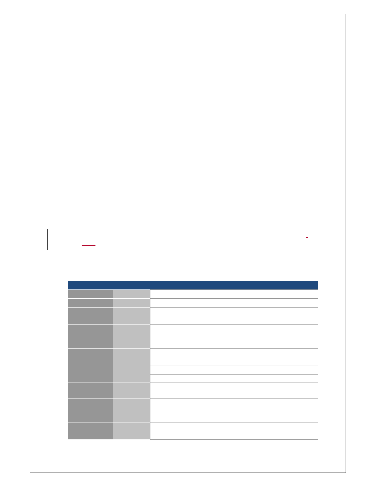
1.1. Introduction
ICM-2010 is a 2.5’’ SBC (Single Board Computer) with ARM Cortex-A9
Freescale i.MX6 DualLite 1GHz processor and ARM Cortex™-M0 32-bit RISC core
(MCU). The ICM-2010 supports 1GB DDR3 and 8MB onboard NOR Flash, 1 x LVDS,
1 x HDMI display, 1 x Gigabit LAN with IEEE 1588, 3 x USB 2.0, 1 x micro USB type
B (device mode only), 1 x RS-232, 1 x RS-485, 1 x CAN, 1 x Full size mini PCIe, 1 x
SD and 1 x SIM (header).
Integrated unique dual hardware structure and RTOS (Real Time Operating
System) design, ICM-2010 has outstanding crash free protection on both
hardware reliability and software stability. With the special features, ICM-2010 is
a perfect device to meet customers’ versatile needs.
The ICM-2010 focuses on industrial application and it provides high
performance and low power consumption from its ARM ® Cortex A9 architecture
which is ready-to-run, compact, and easy-to-expand. With flexible I/O interfaces,
and complete hardware and software solutions, ICM-2010 is a fast time-to-
market platform for customers to develop their applications and products easily.
1.2. Specification
System Hardware - CPU
CPU
Freescale i.MX6 Cortex-A9 DualLite
Memory
Technology
DDR3-800
Capacity
Onboard 1GB
Flash
8MB NOR Flash
Graphic
HDMI
1 x HDMI connector
LVDS
1 x 18/24 bit LVDS header (2x10 1.25mm Hirose DF13 series
compatible)
Watchdog Timer
1~256 level (0.5 second / level)
RTC
EPSON RX8010SJ RTC chip
Indicator
LED
1 x configurable indicator controlled by i.MX6
I/O
LAN
1 x Micrel KSZ9031RNX Gigabit Ethernet
USB
1 x USB (miscellaneous header)
1 x 2 ports USB (double-deck connector)
USB OTG
1 x micro USB type B (device mode only)
Serial Port
1 x RS-232 header (2x5 2.0mm pin header)
1 x RS-485 (1x2 3.5mm terminal block)
CAN
1 x CAN bus header (miscellaneous header-JMISC)
SD socket
1 x SD socket
Page 9
9
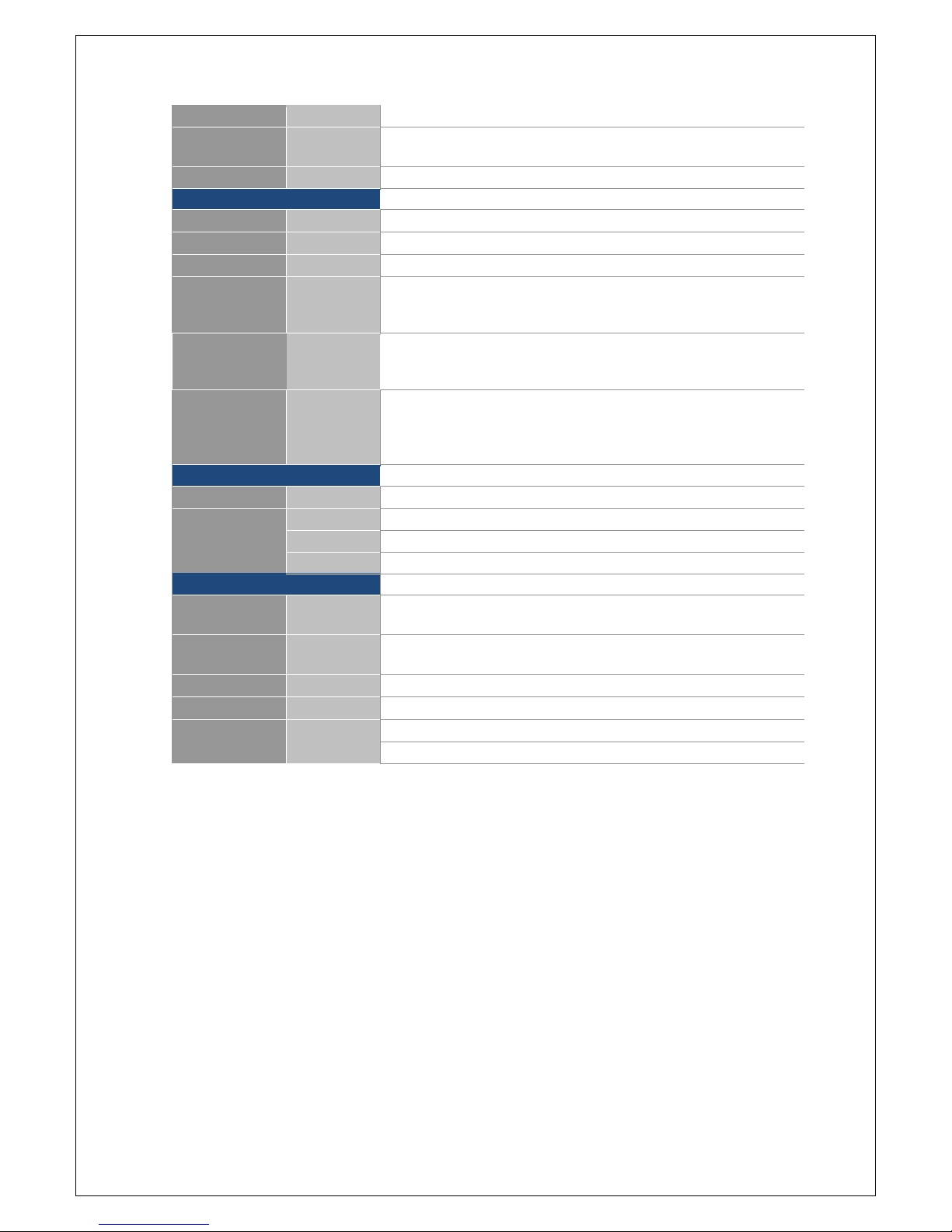
Button
1 x power-on button
Expansion
Full size
mini PCIe
1 x full size mini PCIe socket
SIM slot
1 x SIM card header
System Hardware - MCU
(For EMBUX system product design only)
MCU
STM32F051R8T6
Memory
Flash
8MB NOR Flash
I/O
EMBUX X Port
1 x EMBUX X Port (miscellaneous header-JEMBUX)
I2C
1 x I2C interface (2x10 1.25mm Hirose DF13 series compatible, shared
with SPI and GPIO) for Mainboard MCU to accessory (i.e OLED module)
connection purpose
SPI
1 x SPI interface (2x10 1.25mm Hirose DF13 series compatible, shared
with I2C and GPIO) for Mainboard MCU to accessory (i.e OLED module)
connection purpose
GPIO
7-bit GPIO (2x10 1.25mm Hirose DF13 series compatible, shared with
SPI and I2C) for Mainboard MCU to accessory (i.e OLED module)
connection purpose
2-bit GPIO (5x2 header, pitch 2.0mm-JFP)
System Software
Operating System
ubuntu
Precise 12.04
yocto
Daisy 1.6.2
android
Lollipop 5.0.2
WEC
Windows Embedded Compact 7
Environment & Mechanism
Temperature
Operating
temperature
-20~70° C
Humidity
Operating
humidity
5%~95% Relative Humidity, non-condensing
Mechanism
Dimension
PICO-ITX (100mm X 72mm)
Power
DC-input
5V (4.75V~5.25V)
Control
Power on by DC attached or via power button
Consumption
~3W
Page 10
10
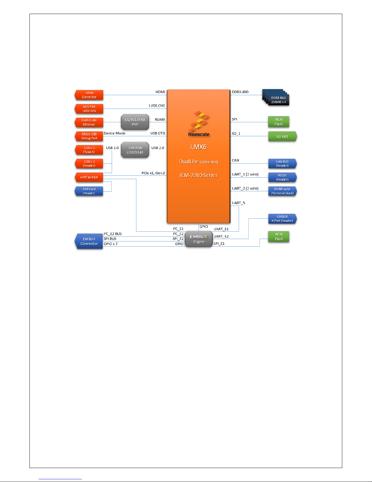
1.3. Block Diagram
Page 11

11
Chapter 2
Hardware User Guide
This chapter introduces the startup procedures of ICM-2010,
including jumper setting and device integration. It also introduces
the setting of switches, indicators and also shows the mechanical
drawings. Be sure to real all safety precautions before you begin
installation procedure.
Page 12
12
2. Hardware User Guide
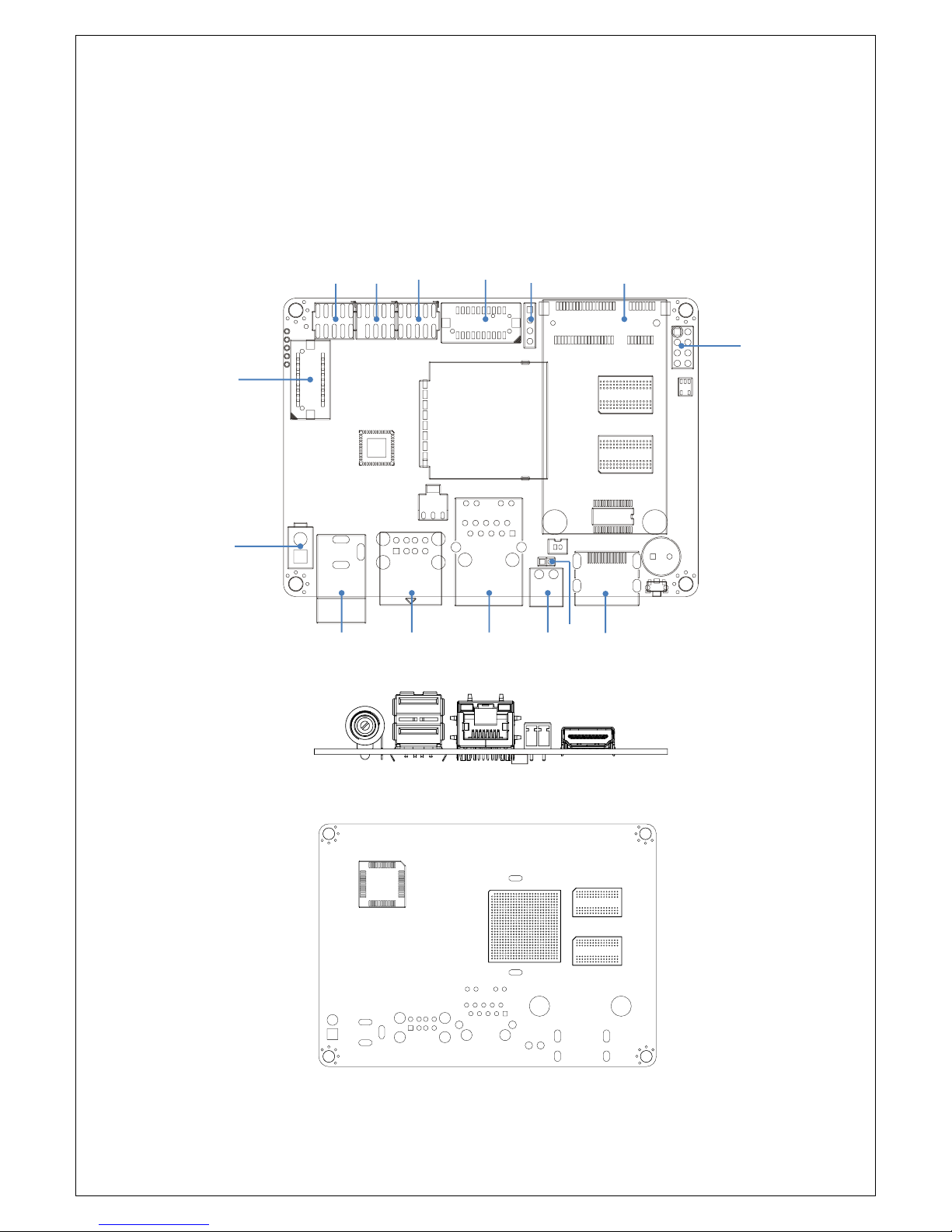
2.1. Connector Locations
Top side:
Rear side:
JFP
JCOM1
JMISC
JLVDS
JI2C
MPCIE
JSIM
JEMBUX
Connector
JDC in
DC in
USB
LAN
RS-485
HDMI
JRS-485
Page 13

13
2.2. Connector
2.2.1. Connector List
DC in
DC power input connector
DC power jack
RS-485
RS-485 connector
2 x 1 connector, pitch 3.5mm
HDMI
HDMI connector
JCOM1
RS-232 pin header
5 x 2 header, pitch 2.0mm
JDC in
Power input pin header
2 x 1 connector, pitch 4.2mm
JEMBUX
Proprietary connector
DF13-20DP-1-25V
JFP
Front panel connector
5 x 2 header, pitch 2.0mm
JI2C
I2C connector
4 x 1 header, pitch 2.54mm
JLVDS
LVDS connector
DF13-20DP-1-25V
JMISC
Miscellaneous connector
5 x 2 header, pitch 2.0mm
JRS-485
Reserved for X-Port connect
2 x 1 header, pitch 2.0mm
JSIM
SIM connector + SATA PWR
4 x 2 header, pitch 2.54mm
LAN
Ethernet connector
RJ-45
MPCIE
Mini PCI Express connector
SATA
SATA connector
USB
USB connector
USB Type A
2.2.2. Connector Pin Definition
2.2.2.1. RS-485
Description
Pin
RS-485-
1
RS-485+
2
Page 14
14
2.2.2.2. JCOM1
Description
Pin
Pin
Description
N/C
1
2
RS-232_RX
RS-232_TX
3
4
N/C
GND
5
6
N/C
N/C
7
8
N/C
N/C
9
10
N/C
2.2.2.3. JDC in
Description
Pin
GND 1 5V
2
2.2.2.4. JEMBUX
Description
Pin
Pin
Description
3.3V
2
1
5V
3.3V
4
3
5V
GPIO0
6
5
GND
GPIO1
8
7
MCU_SS
GPIO2
10
9
MCU_CLK
GPIO3
12
11
MCU_MOSI
GPIO4
14
13
MCU_MISO
GPIO5
16
15
GND
GPIO6
18
17
I2C CLK
N/C
20
19
I2C DAT
Remark:
Match connector: DF13-20DS-1.25C
GPIO pin control by MCU (level 3.3V)
MCU_SS: SPI Slave Select (active low, output from master)
MCU_CLK: SPI Serial Clock (output from master)
MCU_MOSI: SPI Master Output, Slave Input (output from master)
MCU_MISO: Master Input, Slave Output (output from slave)
Page 15
15
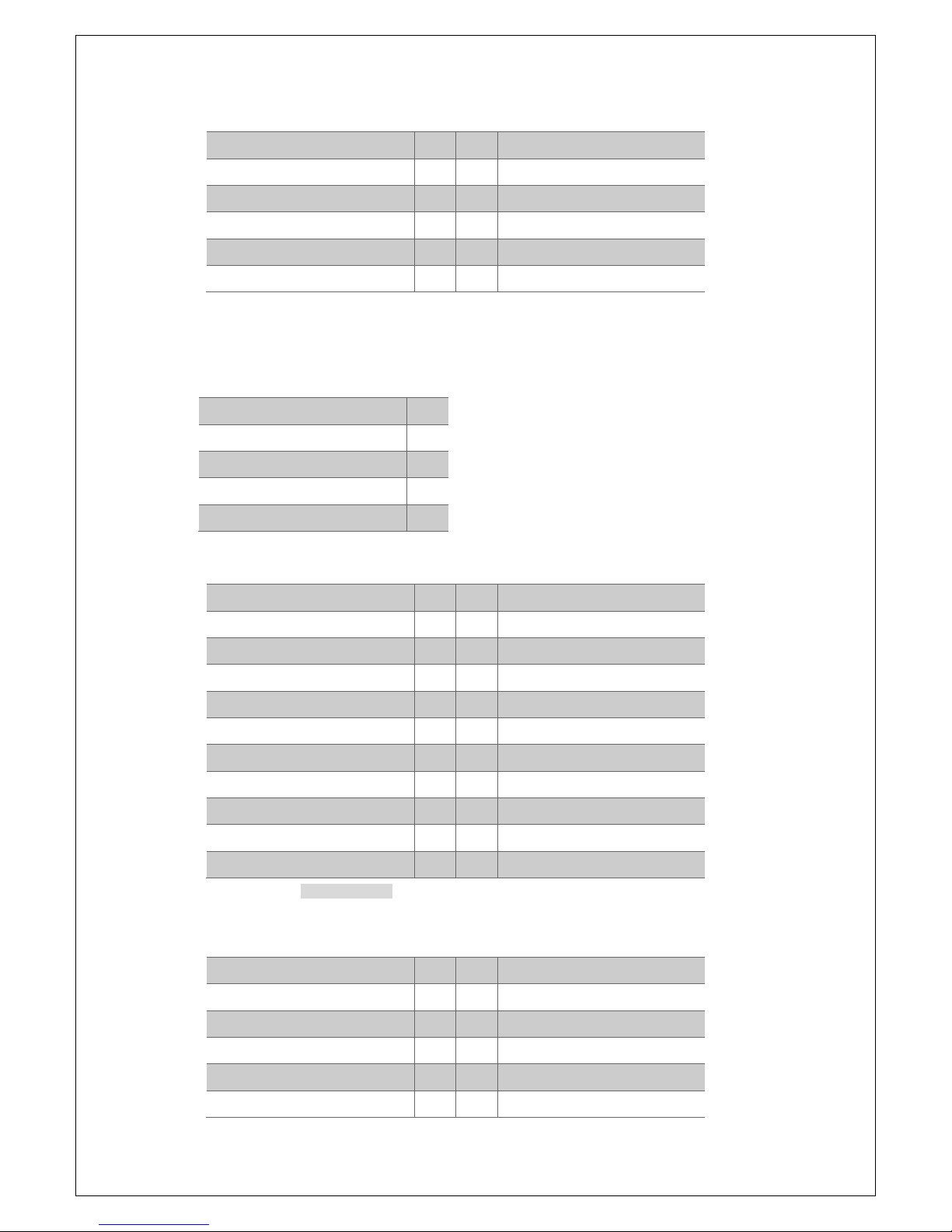
2.2.2.5. JFP
Description
Pin
Pin
Description
5V
1 2 LED control by MCU
5V
3 4 LED control by CPU
CPU power on
5
6
GND
GPIO7
7
8
GND
GPIO8
9
10
GND
Remark:
GPIO pin control by MCU (level 3.3V)
2.2.2.6. JI2C
Description
Pin
3.3V
1
I2C_SCL
2
I2C_SDA
3
GND
4
2.2.2.7. JLVDS
Description
Pin
Pin
Description
3.3V
2
1
5V
3.3V
4
3
5V
Backlight EN (3.3V)
6
5
LVDS0_CLK-
Backlight CTL (3.3V)
8
7
LVDS0_CLK+
GND
10
9
GND
LVDS0_TX1-
12
11
LVDS0_TX0-
LVDS0_TX1+
14
13
LVDS0_TX0+
GND
16
15
GND
LVDS0_TX3-
18
17
LVDS0_TX2-
LVDS0_TX3+
20
19
LVDS0_TX2+
Match connector: DF13-20DS-1.25C
2.2.2.8. JMISC
Description
Pin
Pin
Description
EMBUX X-Port RS-485 TX-
1
2
5V
EMBUX X-Port RS-485 TX+
3
4
USB D-
GND
5
6
USB D+
CAN_H
7
8
GND
CAN_L
9
10
GND
Page 16
16
2.2.2.9. JRS-485
Description
Pin
RS-485TX-
1
RS-485TX+
2
2.2.2.10. JSIM
Description
Pin
Pin
Description
PCIe_UIM_PWR
1 2 PCIe_UIM_RST
PCIe_UIM_CLK
3
4
GND
PCIe_UIM_VPP
5 6 PCIe_UIM_DATA
5V
7
8
GND
Remark:
UIM: User Identity Module (UIM) Signals
UIM_VPP: Variable supply voltage (e.g., programming voltage) for class A devices. This signal is reserved for
future use for devices of other classes. Compliant to the ISO/IEC 7816-3 specification (VPP).
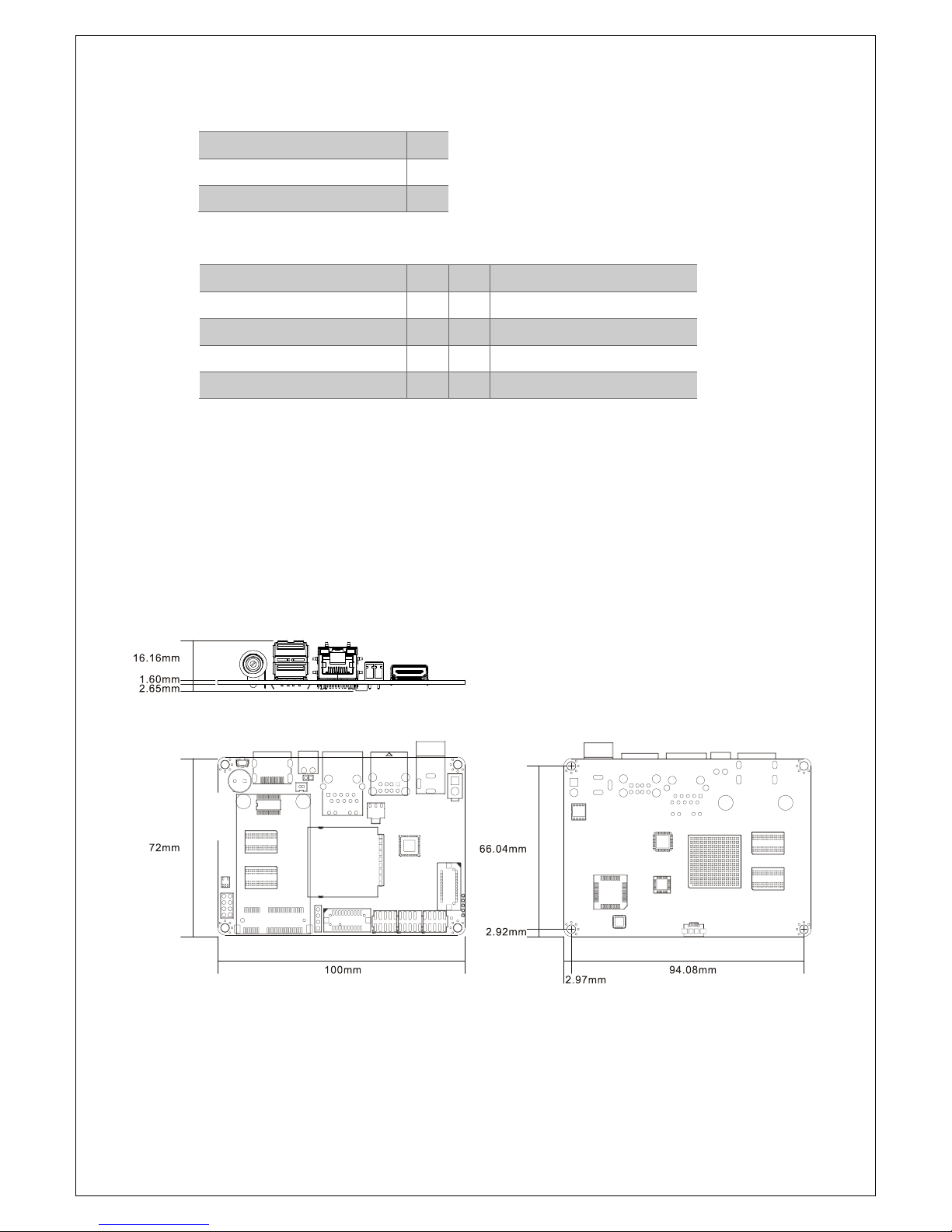
2.3. Mechanical Drawing
Page 17

17
Chapter 3
Software User Guide
This chapter details the Linux operation on ICM-2010.
Page 18

18
3. Software User Guide
3.1. Introduction
This chapter details the Linux operation on ICM-2010 platform. This platform is an
embedded system with Linux kernel 3.0.35. It contains all system-required shell
commands and drivers ready. You can evaluate and develop under Ubuntu 12.04 LTS
environment.
There are three major boot components for Linux, “u-boot.bin”, “uImage” and “root
file system”. The “u-boot.bin” is for initializing peripheral hardware parameters; the
“uIm- age” is the Linux kernel image and the “File System” is for Linux O.S. used.
It will not be able to boot into Linux environment successfully if one of above three
files is missing from booting media (in ICM-2010, we use SD/MMC card)
3.2. Create SD/MMC Card using Linux Host
3.2.1. Requirements
An SD/MMC card reader, like a USB card reader, is required. It will be used to
transfer the boot loader and kernel images to initialize the partition table and copy
the root file system. To simplify the instructions, it is assumed that a 4GB SD/MMC
card is used.
Any Linux distribution can be used for the following procedure. It is recommended to
use a Linux distribution that LTIB has been tested against such as Ubuntu 9.04.
The Linux kernel running on the Linux host will assign a device node to the SD/MMC
card reader. The kernel might decide the device node name or udev rules might be
used. In the following instructions, it is assumed that udev is not used.
To identify the device node assigned to the SD/MMC card, enter the command:
$ cat /proc/partitions
major minor #blocks name
8 0 175825944 sda
8 1 254976 sda
8 2 1 sda
8 5 175567872 sda
8 0 7761920 sdb
8 0 2048000 sdb
In this example, the device node assigned is /dev/sdb (a block is 512B large).
Page 19

19
Download the u-boot & Kernel Images for ICM-2010 SD card image: go to
https://github.com/embux/ , and choose the right image for your platform (in this case: ICM-
2010-images.tar.gz). Extract the file for preparing the SD/MMC images download.
3.2.2. SD/MMC Partitions
The layout of the MMC/SD/TF card for Android system is shown below:
Model: Generic- SD/MMC (scsi)
Disk /dev/sdc: 7884MB
Sector size (logical/physical): 512B/512B
Partition Table: msdos
No. Name Size Type File-System
1 rootfs 7.3G primary ext4
2 recovery 32MB primary ext4
3 1K extended
5 1KB logical
6 1MB logical
7 1MB logical
8 1MB logical
9 storage 500MB logical fat16
10 env 90MB logical fat16
In order to create the SD card, the partition table must be created. If a partition
already exists and it is big enough for the file system you want to deploy, then you
can skip this step.
Below is a partition example for partition 1 (rootfs).
To create a partition, at offset 32768 (in sectors of 512 bytes) enter the following
command:
$ sudo fdisk /dev/sdb
Note: On most Linux host operating systems, SD card will be mounted automatically
upon insertion. Therefore, before running fdisk, please make sure that SD card is
unmounted (via 'sudo umount /dev/sdb').
Type the following parameters (each followed by <ENTER>):
Page 20

20
u [switch the unit to sectors instead of cylinders]
d [repeat this until no partition is reported by the ‘p’ command ]
n [create a new partition]
p [create a primary partition]
1 [the firs partition]
32768 [start at offset sector #32768, i.e. 16MB, which leaves enough space for the
kernel, the boot loader and its configuration data]
<enter> [using the default value will create a partition that spans to the last sector
of the medium]
w [this writes the partition table to the medium and fdisk exits]
Use the commands above to create rest 9 partitions to complete the partition table.
3.2.3. Copying the Boot loader Image
Once the partition table is ready, enter the following command to copy the U-Boot
image to the SD/MMC card:
$ sudo dd if=u-boot.imx of=/dev/sdb bs=1k seek=1 conv=fsync
3.2.4. Copying the Kernel Image and Device Tree Files
The following command will copy the kernel image and device tree files to the
SD/MMC card:
$ sudo mount –t vfat /dev/sdb10 /home/user/mountpoint
$ cp uImage /home/user/mountpoint
$ cp boot-env /home/user/mountpoint
$ cp imx6dl-embux-icm2010.dtb /home/user/mountpoint
$ sync
$ sudo umount /home/user/mountpoint
3.2.5. Copying the Root File System (rootfs)
The file system format ext3 or ext4 is a good option for removable media due to the
built- in journaling. Run the following command to format the partition:
$ sudo mkfs.ext3 /dev/sdb1
Or
$ sudo mkfs.ext4 /dev/sdb1
Copy the target file system to the partition:
Page 21

21
$ mkdir /home/user/mountpoint
$ sudo mount /dev/sdb1 /home/user/mountpoint
Download and save the demo rootfs from https://releases.linaro.org/12.04/ubuntu/precise-
images/ubuntu-desktop/linaro-precise-ubuntu-desktop-20120426-119.tar.gz
Extract rootfs package to certain directory: extract rootfs.ext2.gz to
/home/user/rootfs for example:
$ gunzip rootfs.ext2.gz
$ mount -o loop -t ext2 rootfs.ext2 /home/user/rootfs
Assume that the root file system files are located in /home/user/rootfs as in the
previous step:
$ cd /home/user/rootfs
$ sudo cp -a * /home/user/mountpoint
$sync
$ sudo umount /home/user/mountpoint
The file system content is now on the media.
3.3. Applications and Testing
3.3.1. Ethernet Test
A simple ping test. You can increase the size of the packet press -s switch
# ping -s 500 192.168.0.100
PING 192.168.0.100 (192.168.0.100): 1000 data bytes
1008 bytes from 192.168.0.100: seq=0 ttl=64 time=1.980 ms
1008 bytes from 192.168.0.100: seq=1 ttl=64 time=0.459 ms
1008 bytes from 192.168.0.100: seq=2 ttl=64 time=0.461 ms
1008 bytes from 192.168.0.100: seq=3 ttl=64 time=0.475 ms
--- 192.168.0.100 ping statistics --4 packets transmitted, 4 packets received, 0% packet loss
…
3.3.2. USB
Plug in a USB memory stick, you will see a message like this (possible use dmesg
Page 22

22
command to see how your USB is detected).
# usb 1-1.1: device v17ef p3818 is not supported
sd 1:0:0:0: [sdc] No Caching mode page present
sd 1:0:0:0: [sdc] Assuming drive cache: write through
sd 1:0:0:0: [sdc] No Caching mode page present
sd 1:0:0:0: [sdc] Assuming drive cache: write through
sd 1:0:0:0: [sdc] No Caching mode page present
sd 1:0:0:0: [sdc] Assuming drive cache: write through
Mount the USB (in this example the USB is formatted as FAT)
# mount /dev/sdc1 /media
# ls -la /media
Now, you can copy a video to /media and play it. This will perform a simple USB test.
3.3.3. SD
Plug the SD card and find out where the card is mapped. After typing dmesg at you
will see something like this:
# dmesg | tail
mmc0: new high speed SD card at address aaaa
mmcblk1: mmc0:aaaa SU02G 7.8 GiB
mmcblk1: p1
Your card is mapped in /dev/mmcblk0.
3.3.4. I2C
# sudo apt-get install i2c-tool
# i2cdetect 1
WARNING! This program can confuse your I2C bus, cause data loss and worse!
I will probe file /dev/i2c-1. I will probe address range 0x03-0x77. Continue? [Y/n] y
0 1 2 3 4 5 6 7 8 9 a b c d e f
00: -- -- -- -- -- -- -- -- -- -- -- -- --
10: -- -- -- -- -- -- -- -- -- -- -- -- -- -- -- --
20: -- -- -- -- -- -- -- 27 -- -- -- -- -- -- -- --
30: 30 -- -- -- -- -- -- 37 -- -- -- -- -- -- -- --
40: -- -- -- -- -- -- -- -- 48 -- 4a 4b -- -- -- --
50: UU 51 -- -- -- -- -- -- -- -- -- -- -- -- -- --
60: -- -- -- -- -- -- -- -- -- -- -- -- -- -- -- --
70: -- -- -- -- -- -- -- -- # [/code]
Page 23

23
3.4. Create a Virtual Machine Environment
3.4.1. Introduction
The use of a virtual machine running a specific Linux Ubuntu distribution is highly
recommended. A virtual machine will create a dedicated, close environment that will
ensure that a step-by-step procedure will guide the user until the end without
problems.It also prevent risks ofsystem corruption or that compiling environment is
not clean It also allows to be sure that used libraries are always the same, and
updated.
System RequirementsTo run the procedure described in the following sections, it is
necessary to have: PC with virtual machine running Linux Ubuntu 10.04 with at least
40 GB of free disk space.
This procedure can be performed also on native Linux OS. The use of a VM only
reduces system differences and can follow a standard procedure to compile.
3.4.2. Setting up work environment
Install the Virtual Machine
VMware PlayerTM is recommended for this operation. A step-by-step installation
Procedure is provided.
Download the VM playerDownload the player from VMware Player website:
You can find the latest st version at http://www.vmware.com/products/player/ .
Choose the version dedicated to the OS used.
Install the VM on your systemOpen the installer and follow the instructions.
For more information, check the VMware documentation:
http://www.vmware.com/pdf/VMwarePlayerManual10.pdf
Download Ubuntu disk imageA 64 bit 10.04 Ubuntu distro to run this procedure is
recommended. It can be downloaded from http://oldreleases.ubuntu.com/releases/lucid/
Create a new VM running Ubuntu 10.04 Click on VMware Player icon.
Choose “Create a New Virtual Machine” from menu on the rightChoose “Installer
disk image file (iso)” and select the downloaded ubuntu iso image.. Press Next
Page 24

24
button.Then choose your name, the username and the password. Fill these fields
and click on next button.Choose the VM name: EA21-10.04 and click next.Set
harddisk size at least 20 GB. Select “split virtual disk into multiple files” option.Now
it is necessary to set VM performances by clicking on “customize hardware” button.
Memory Options:
- 2 GB minimum (memory swapping especially during java compiling)
- 4 GB+ perfect (no memory swapping during build operations)
Attention
The memory size must be chosen according to the amount of free memory
on the host computer. When large amount of memory are assigned to VM,
then the host OS could repeatedly swap or page, leading to a drastic decrease
of computer’ s performances.
CPUs:All the available CPU cores of the host PC should be assigned to VM
execution, especially for the first compiling which requires a lot of time. After
the first phase, it is possible to reduce the number of CPU cores, if desired.
Then click on “Finish” button and Ubuntu installation will start.When the
installation has ended, it is possible that it is necessary to login from console
and launch the GUI by running the command:
startx
Setting up VM environment
Update the system:
$ sudo apt-get update
Install required libraries for compiling process:
$ sudo apt-get install git-core gnupg flex bison gperf build-essential \ zip
curl zlib1g-dev libc6-dev lib32ncurses5-dev ia32-libs \ x11proto-core-dev libx11dev lib32readline5-dev lib32z-dev \ libgl1-mesa-dev g++-multilib mingw32
tofrodos python-markdown \ libxml2-utils xsltproc uuid-dev liblzo2-dev
Page 25

25
Chapter 4
System Recovery
This chapter introduces how to recover Linux operating system if it
is damaged accordingly.
Page 26
26
4. System Recovery
This chapter describes the steps to create a new SD/MMC card to boot up an ICM2010 board. When things go wrong, we could take this SD/MMC card as the backup
or the new system to start.
4.1. Download the SD image
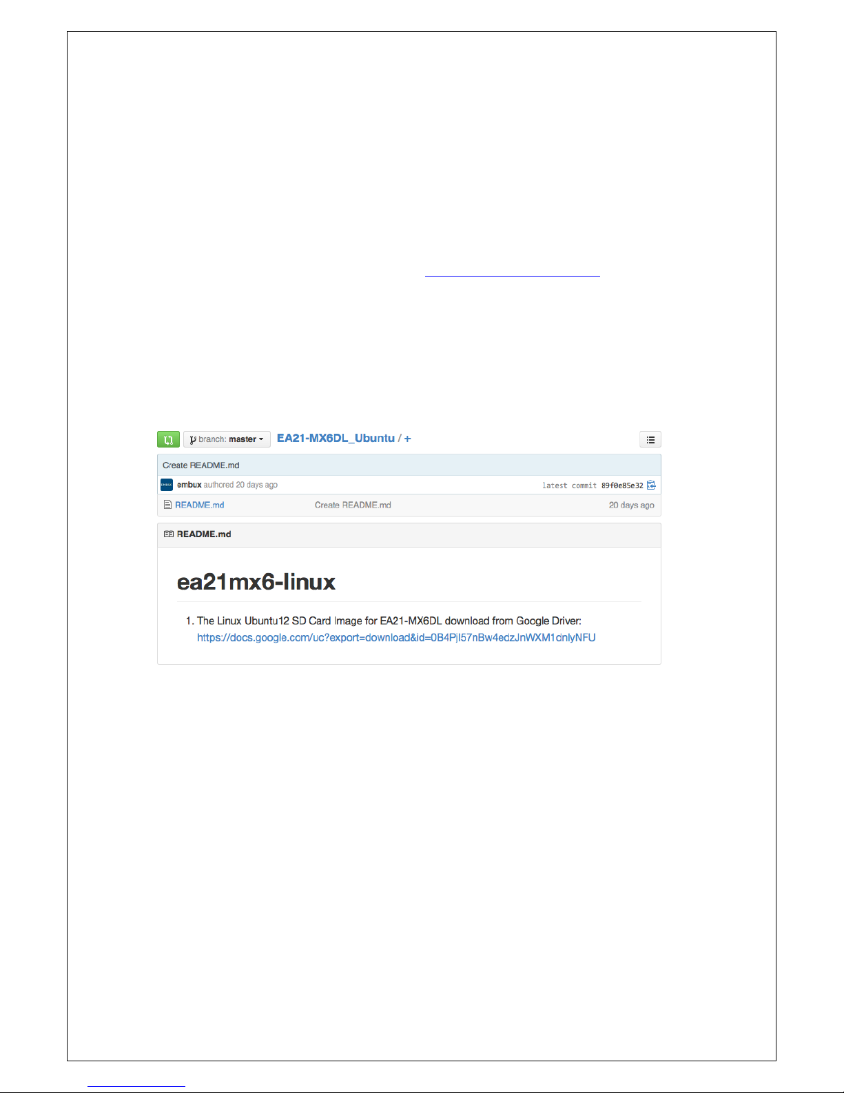
Downloaded the SD card image: go to https://github.com/embux/ , and choose
the right image for your platform (in this case: ICM-2010_Ubuntu), in Readme.md
part, you will find the link for “The Linux Ubuntu12 SD Card Image for ICM-2010
download from Google Driver”, just click on it and it will start download immediately.
Once download has finished, you’ll have a .xz file (ex: ea2mx6dl-ubuntu12-
full.img.xz ).
4.2. Write an SD/MMC Card using Linux (Ubuntu)
From the terminal run df -h.
Connect the SD card reader with the SD card inside.
Run df -h again and look for the new device that wasn't listed last time.
Record the device name of the filesystem's partition, for example: /dev/sdc1.
Unmount the partition so that you will be allowed to overwrite the disk:
sudo unmount /dev/sdc1
Decompressed the xz file which download in sec 4.1
Page 27

27
$ xz –d ubuntu12-full.img.xz
In the terminal, write the image to the card with this command, using the
disk device name from above. Read the above step carefully to be sure you
use the correct disk number here: (This will take a few minutes)
$ sudo dd if=<image_path>/ubuntu12-full.img of=/dev/sdc bs=8M conv=fsync
4.3. Write an SD/MMC Card using Windows
4.3.1. Introduction
This guide describes the process of writing these images to a SD-Card on a Windows
PC (under Linux you would use the dd command).
4.3.2. Preparations
Download the SD-Card image which described in Chap 4.1.
The downloaded file is in the xz file format and needs to be uncompressed. xz
utility (http://tukaani.org/xz/) can be used if no suitable application is
installed on your computer
Make sure that your target SD-Card is big enough to contain this file (8G
recommend )
Download and unzip Image Writer for Windows
(http://sourceforge.net/projects/win32diskimager/files/)
4.3.3. Create SD-Card
Insert the SD-Card into your computer and check which drive letter it got
assigned
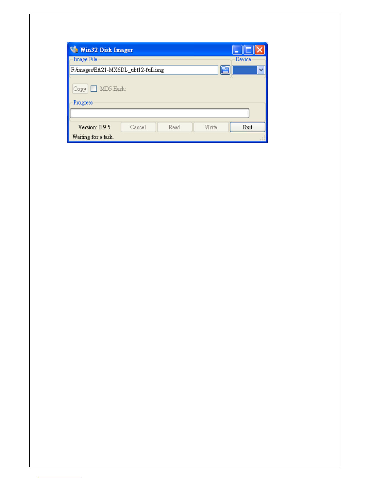
Open Win32DiskImager.exe
o Click the FileOpen Icon and select the unzipped .bin file
o Select the letter of your SD-Card in the device drop-down menu
o Double check if you have chosen the right drive! You may damage
your PC or data otherwise.
Page 28
28
Press write to start writing the image to the card. (This may take a couple of
minutes)
After the Program is finished, you can eject your SD-Card.
Insert it into your target device, plug-in power cable and you could start using
the device
4.4. Write an SD/MMC Card using MAC OS X
On Mac OS we could use the command line dd tool or using the graphical tool
ImageWriter to write the image to the SD/MMC card.
4.4.1. graphical interface
Connect the SD card reader with the SD card inside. Note that it must be
formatted in FAT32.
From the Apple menu, choose About This Mac, then click on More info...; if
you are using Mac OS X 10.8.x Mountain Lion or newer then click on System
Report.
Click on USB (or Card Reader if using a built-in SD card reader) then search for
your SD card in the upper right section of the window. Click on it, then search
for the BSD name in the lower right section; it will look something like 'diskn'
where n is a number (for example, disk4). Make sure you take a note of this
number.
Unmount the partition so that you will be allowed to overwrite the disk; to do
this, open Disk Utility and unmount it (do not eject it, or you will have to
reconnect it). Note that On Mac OS X 10.8.x Mountain Lion, "Verify Disk"
Page 29

29
(before unmounting) will display the BSD name as "/dev/disk1s1" or similar,
allowing you to skip the previous two steps.
From the terminal run:
sudo dd bs=1m if=<image_path>/ubuntu12-full-image.img
of=/dev/diskn
Remember to replace n with the number that you noted before!
4.4.2. Command line
If you are comfortable with the command line, you can image a card without
any additional software. Run:
diskutil list
Identify the disk (not partition) of your SD card e.g. disk4 (not disk4s1):
diskutil unmountDisk /dev/<disk# from diskutil>
e.g. diskutil unmountDisk /dev/disk4
sudo dd bs=1m if=image.img of=/dev/<disk# from diskutil>
e.g. sudo dd bs=1m if=2015-02-16-raspbian-wheezy.img
of=/dev/disk4
This may result in an dd: invalid number '1m' error if you have GNU coreutils
installed. In that case you need to use 1M:
sudo dd bs=1M if=image.img of=/dev/<disk# from diskutil>
This will take a few minutes.
4.4.3. Alternative method
Note: Some users have reported issues with using Mac OS X to create SD cards.
These commands and actions need to be performed from an account that has
administrator privileges.
From the terminal run df -h.
Page 30

30
Connect the SD card reader with the SD card inside.
Run df -h again and look for the new device that wasn't listed last time.
Record the device name of the filesystem's partition, for example
/dev/disk3s1.
Unmount the partition so that you will be allowed to overwrite the disk:
sudo diskutil unmount /dev/disk3s1
(or open Disk Utility and unmount the partition of the SD card (do not eject it,
or you will have to reconnect it)
Using the device name of the partition, work out the raw device name for the
entire disk by omitting the final "s1" and replacing "disk" with "rdisk". This is
very important as you will lose all data on the hard drive if you provide the
wrong device name. Make sure the device name is the name of the whole SD
card as described above, not just a partition of it (for example, rdisk3, not
rdisk3s1). Similarly, you might have another SD drive name/number like
rdisk2 or rdisk4; you can check again by using the df -h command both
before and after you insert your SD card reader into your Mac. For example,
/dev/disk3s1 becomes /dev/rdisk3.
In the terminal, write the image to the card with this command, using the raw
disk device name from above. Read the above step carefully to be sure you
use the correct rdisk number here:
sudo dd bs=1m if=image.img of=/dev/rdisk3
If the above command reports an error (dd: bs: illegal numeric value),
please change bs=1m to bs=1M.
If the above command reports an error dd: /dev/rdisk3: Permission
denied then that is because the partition table of the SD card is being
protected against being overwritten by MacOS. Erase the SD card's partition
table using this command:
sudo diskutil partitionDisk /dev/disk3 1 MBR "Free Space"
"%noformat%" 100%
That command will also set the permissions on the device to allow writing.
Now try the dd command again.
Page 31

31
Note that dd will not feedback any information until there is an error or it is
finished; information will be shown and the disk will re-mount when
complete. However if you wish to view the progress you can use 'ctrl-T'; this
generates SIGINFO, the status argument of your tty, and will display
information on the process.
After the dd command finishes, eject the card:
sudo diskutil eject /dev/rdisk3
(or: open Disk Utility and eject the SD card)
 Loading...