

Page 1

embla
® ™
®
Sandman Digital 32+ Amplifier
User Manual
Page 2

Sandman Digital 32+ Amplifier User Manual
Applies to the Sandman Digital 32+ Amplifier, Sandman elink Adapter, and Sandman DC Expansion (DCX) Box
Copyright © 2012 Embla Systems. All rights reserved.
Issued May 2012. Printed in the USA or The Netherlands.
Document Number: D-1002-001, Revision 3.0
Document Item Number: 4280034
For assistance, please contact Embla Technical Support ([email protected]).
MANUFACTURER EUROPEAN REPRESENTATIVE
Embla Systems
1 Hines Rd, Suite 202
Kanata, ON K2K 3C7
Canada
Tel: +1.613.254.8877
Fax: +1.613.270.0627
TOLL-FREE IN NORTH AMERICA: 888 NO APNEA (888.662.7632)
www.embla.com [email protected] [email protected]
Natus Europe GmbH
Robert-Koch-Str. 1
82152 Planegg
Germany
Tel: +49 089 83942-0
Fax: +49 089 83942-777
Disclaimer
This document may contain technical inaccuracies or typographical errors. Embla does not accept any liability for
the use or misuse, direct or indirect, of this product. Users must accept all responsibility for any results obtained by
or concluded from the products. All clinical conclusions and decisions that are made based on the use of this
product are the responsibility of the user. Embla does not accept any liability or responsibility for damages
arising out of the use of or inability to use this product.
Copyright
Information in this document, including URL and other Internet website references, is subject to change without
notice. Complying with all applicable copyright laws is the responsibility of the user. Without limiting the rights
under copyright, no part of this document may be altered for any purpose, without the express written permission
of Embla. The subject matter in this document is the express property of Embla. Unless specifically provided in any
written license agreement from Embla, the furnishing of this document does not give you any license to these
trademarks, copyrights, or other intellectual property.
Trademarks
Embla, Sandman, and Sandman Elite are registered trademarks of Embla Systems. Sandman Digital 32+ and
Sandman elink are trademarks of Embla Systems. All other trademarks are the property of their respective
owners.
The Sandman Digital 32+ Amplifier is certified to carry the CE mark. The CE mark is a declaration
0051
that the Sandman Digital 32+ Amplifier is in compliance with the directive for medical devices set
forth by the European Union.
The cCSAus mark is a safety symbol that shows the product has been independently tested and
certified to applicable U.S. and Canadian product safety standards.
MANUFACTURED IN ITALY BY:
EBNeuro S.p.A.
via Pietro Fanfani 97/A
50127 Firenze
ITALY
Distributed by Embla Systems.
Page 3

Table of Contents
1. General Warnings and Cautions ......................................................................................................... 1
1.1. intended use .......................................................................................................................................... 1
1.2. safety information and document conventions ................................................................................ 1
1.3. warnings ................................................................................................................................................ 1
1.4. amplifier casing symbols ..................................................................................................................... 2
1.5. electromagnetic compatibility ............................................................................................................. 3
1.5.1. recommended distance from Radio Frequency systems .................................................... 4
2. Safety .................................................................................................................................................. 6
2.1. operational environment ..................................................................................................................... 6
2.1.1. electrical safety ......................................................................................................................... 7
2.1.2. patient leakage current ............................................................................................................ 8
2.1.3. patient connection .................................................................................................................... 8
2.2. LCD display ........................................................................................................................................... 8
2.3. declaration of conformity .................................................................................................................... 9
2.4. caution for the U.S. market .................................................................................................................. 9
3. Introduction ...................................................................................................................................... 10
3.1. Sandman Digital 32+™ amplifier (SD32+) ...................................................................................... 10
3.2. headbox ................................................................................................................................................ 11
3.3. amplifier ............................................................................................................................................... 15
3.4. LCD display ......................................................................................................................................... 17
3.5. integrated pulse oximeter .................................................................................................................. 18
3.6. Sandman elink™ adapter .................................................................................................................... 19
3.7. power supply ...................................................................................................................................... 20
3.8. DC expansion box ............................................................................................................................... 21
®
connectors ......................................................................................................................................... 11
electrode sockets .............................................................................................................................. 12
ports ................................................................................................................................................... 16
sockets ............................................................................................................................................... 16
3.7.1. external medical grade ac/dc adapter ................................................................................ 20
3.7.2. amplifier power modes ......................................................................................................... 21
3.7.3. surge protection ..................................................................................................................... 21
inputs ................................................................................................................................................. 22
4. Software Driver Installation ............................................................................................................. 23
5. Amplifier System Assembly .............................................................................................................. 24
5.1. connecting the headbox to the amplifier ......................................................................................... 24
5.2. connecting the amplifier to the sandman elink adapter .................................................................. 24
5.3. connecting the external power supply to the amplifier system ................................................... 24
5.4. connecting the DC expansion box to the computer (serial connection) ...................................... 25
5.5. connecting the DC expansion box to the computer (USB connection) ........................................ 25
6. Calibration ......................................................................................................................................... 27
6.1. system record calibration .................................................................................................................. 27
7. Maintenance ..................................................................................................................................... 28
7.1. safety checks ........................................................................................................................................ 28
7.2. operational environment electrical equipment .............................................................................. 28
7.3. amplifier calibration ........................................................................................................................... 28
i
Page 4

7.4. cables and connectors ......................................................................................................................... 28
7.5. cleaning ................................................................................................................................................ 29
8. Specifications .................................................................................................................................... 30
8.1. system specifications .......................................................................................................................... 30
8.2. environmental operating conditions ................................................................................................ 31
8.3. environmental conditions for storage .............................................................................................. 31
8.4. amplifier specifications ...................................................................................................................... 31
8.4.1. general amplifier specifications ........................................................................................... 31
8.4.2. filters ........................................................................................................................................ 32
8.4.3. resolution, full scale range, noise ......................................................................................... 32
8.4.4. sampling rate .......................................................................................................................... 33
8.5. headbox specifications ....................................................................................................................... 33
8.6. external medical grade AC/DC adapter specifications ................................................................ 34
8.6.1 AULT SW173 ........................................................................................................................ 34
8.6.2 SINPRO MPU50-106 ........................................................................................................... 34
8.7. Sandman elink™ adapter ................................................................................................................... 35
8.8. DC expansion box specifications ...................................................................................................... 35
8.9. pulse oximeter performance ............................................................................................................. 36
®
8.8.1. technical characteristics ......................................................................................................... 35
8.8.2. environmental conditions ..................................................................................................... 36
List of Figures
Figure 1. the SD32+ system ...................................................................................................................... 11
Figure 2. the headbox amplifier connection port .................................................................................. 12
Figure 3. removable patient box (headbox) link port ........................................................................... 12
Figure 4. headbox to amplifier cable ....................................................................................................... 12
Figure 5. headbox electrode sockets ........................................................................................................ 13
Figure 6. SD32+ amplifier’s external connections (front) ..................................................................... 15
Figure 7. SD32+ amplifier’s external connections (back) ..................................................................... 15
Figure 8. Sandman elink adapter ............................................................................................................... 19
Figure 9. fiber optic cable .......................................................................................................................... 20
Figure 10. external medical grade ac/dc adapter ................................................................................. 20
Figure 11. power transfer cable ............................................................................................................... 21
Figure 12. dc expansion box input sockets ............................................................................................. 22
Figure 13. SD32+ amplifier dc expansion box cable ............................................................................. 25
Figure 14. typical SD32+ system set-up .................................................................................................. 26
List of Tables
Table 1. electromagnetic emission ............................................................................................................. 3
Table 2. electromagnetic immunity ........................................................................................................... 4
Table 3. recommended distances ............................................................................................................... 5
Table 4. SD32+ amplifier headbox sockets ............................................................................................. 14
ii
Page 5

SD32+
System General Warnings and Cautions
1. General Warnings and Cautions
This document contains proprietary information. No part of this publication may be reproduced
in any form without written permission from Embla Systems.
1.1. intended use
The Sandman® Digital 32+™ Amplifier ("SD32+") is intended to be used by or under the direction
of a physician for acquisition of EEG, polygraphy, and polysomnography signals and
transmission of these signals to a PC during recording of neurophysiology examinations.
1.2. safety information and document conventions
The following table describes the safety and document conventions found in this manual:
Warning
Caution
Note
The Warning message appears in this manual before procedures or tasks
that must be strictly observed to avoid patient harm, inaccurate
measurements, or loss of data.
The Caution message appears in the manual before procedures or tasks that
must be strictly observed to avoid damage to the product.
The Notes message contains important information to help the operator
complete a procedure or task correctly.
1.3. warnings
1. Do not disassemble the SD32+ or Headbox.
2. All connections on the Headbox are isolated from the ground of your building’s
electrical system (AC power ground). This type of insulation is known as “floating
isolation”. To avoid injury to the patient, do not connect input signals to the
Headbox from devices that are not equipped with floating isolation.
3. To maintain the SD32+ electrical isolation ensure that neither the patient nor any
conductive part connected to the patient (such as electrodes or sensors) comes into
contact with any conductive material.
4. Verify that the building’s electrical wiring is in good condition and properly
grounded. To ensure the safety of both patient and technician make certain that any
AC powered device connected to the SD32+ is properly grounded.
5. Always follow the safety precautions outlined in chapter 2. Safety on page 6 of this
manual.
6. Place the computer outside of the patient area. If this is not possible, power the
computer through a dedicated isolation transformer.
7. Carefully route and secure sensor cables to avoid patient entanglement or
strangulation.
1
Page 6

General Warnings and Cautions
1.4. amplifier casing symbols
This symbol identifies ports or sockets equipped with a Type BF level of electrical
isolation in accordance with IEC60601-1.
This symbol prompts the user to refer to this manual for proper usage and safety
instructions.
This symbol identifies input connectors.
This symbol identifies output connectors.
This symbol identifies the manufacturing date
SD32+
System
REF
SN
This symbol identifies the part number of the device
This symbol identifies the serial number of the device
2
Page 7

SD32+
System General Warnings and Cautions
1.5. electromagnetic compatibility
This device is designed for use in environments that comply with IEC 60601-1-2:2001 as indicated
in the tables shown. You must ensure that the device is used in compliance with the IEC
standards.
Emission Test Compliance Electromagnetic Environment
Radiated and Conducted RF
emission
CISPR 11
Harmonic emission
IEC 61000-3-2
Voltage fluctuations/flicker
emissions
IEC 61000-3-3
Table 1. electromagnetic emission
Immunity Test IEC 60601-1-2 Test Level Compliance Electromagnetic
Electrostatic
Discharge
(ESD)
IEC 61000-4-2
Electrical fast
transient/burst
IEC 61000-4-4
Surge
IEC 61000-4-5
Voltage dips,
short
interruptions
and voltage
variation on
power supply
input lines
IEC 61000-4-11
6 kV direct contact
8 kV through air
2 kV for power supply line
1 kV for input/output line
>3m
1 kV differential mode
2 kV common mode
0% of rated voltage (voltage
dip 100%) for 0.5 cycles
40% of rated voltage
(voltage dip 60%) for 5
cycles
70% of rated voltage
(voltage dip 30%) for 25
cycles
0% of rated voltage (voltage
dip 100%) for 5 cycles
Class B The device is suitable for use in domestic and
other environments that are connected to a low
voltage power supply.
Group 1 The internal operation uses a low RF. The
emission is not likely to cause interference with
nearby electronic equipment.
Complies The device may be connected directly to a low
voltage supply using an electrical ground.
Complies The device may be connected directly to a low
voltage supply using an electrical ground.
environment
IEC 60601-1-2 Test
Levels
IEC 60601-1-2 Test
Levels
IEC 60601-1-2 Test
Levels
Residential
Residential
(Note 1)
Residential
(Note 2)
(Note 3)
Residential
(Note 2)
(Note 3)
(Note 2)
(Note 3)
3
Page 8

General Warnings and Cautions
Immunity Test IEC 60601-1-2 Test Level Compliance Electromagnetic
environment
Magnetic fields
at ground
frequency
(50/60Hz)
IEC 61000-4-8
Radiated RF
fields
IEC 61000-4-3
Conducted RF
fields
IEC 61000-4-6
Note 1 – The floor should be antistatic (wood, ceramic, etc.). If carpeted, the relative humidity
should be maintained at 30%.
Note 2 – The main power supply must be of residential, commercial, or medical grade.
Note 3 – If operating for an extended period, a UPS system must be provided in the event of a
power outage.
Note 4 – Mobile or portable RF communication devices should be used at greater distances than
those provided in table 3.
Table 2. electromagnetic immunity
3 A/m
Non-life-supporting
equipment
3 V/m
From 80 MHz to 2.5 GHz
Non-life-supporting
equipment
3 V
From 150 kHz to 80 MHz
Measures to observe
IEC 60601-1-2 Test
Levels
Residential
(Note 4)
SD32+
System
1.5.1. recommended distance from Radio Frequency systems
It is not recommended to use RF transmitting devices near the SD32+ digital amplifier. RF
transmitting devices can cause interference with the device and impact the quality of the signals
being acquired during use.
To prevent RF interference it is recommended to maintain a minimum distance between the
SD32+ digital amplifier and the RF transmitting device being used; such as cell/mobile phones.
The following table shows recommended distances that the SD32+ digital amplifier should
remain from some common RF transmitting devices.
RF Source Typical Rated
Power (W)
Microcellular phone CT1, CT2, CT3 0.01 0.3
DECT cellular phone, Wireless Information
Technology equipment (modems, LAN's)
Cellular phone, hand-held (USA) 0.6 2
Cellular phone, hand-held (GSM and NMT,
Europe DECS 1800)
Walkie-talkie (Rescue, police, fire, maintenance) 5 3
Cellular phone, bag 16 10
Mobile radio (Rescue, police, fire) 100 30
0.25 2
2
8
Distance
(m)
4
7
4
Page 9

SD32+
System General Warnings and Cautions
For transmitters, the maximum output power of which is not within the values above, the
recommended distance can be estimated by using the following calculations:
For transmitters using a frequency range from 150 kHz to 80 MHz and 80MHz t o 800 MHz, the
distance can be estimated as follows:
D = 1.2√P
For transmitters using a frequency range from 800 MHz to 2.5 GHz, the distance can b e
estimated as follows:
D = 2.3√P
P = the rated power of the transmitter in Watts (W).
Note: Always use the greater distance provided.
Note: These values are general guidelines as electromagnetic fields can be co mpromised in
the presence of structures, objects, and people.
Table 3. recommended distances
Always remember that the intensity of the electromagnetic field generated by a fixed transmitter
(base station for radio, TV, Cell service, etc.) cannot be predicted.
Additional measures may be required if the electromagnetic field exceeds the specified intensity
shown in table 3.
5
Page 10

Safety
SD32+
System
2. Safety
Please follow all warnings and cautions listed in this manual to ensure the safety of the patient
and the operator.
Warning: Before using the SD32+ system, ensure that it satisfies all safety requirements.
Safety checks should be performed periodically and no less than twice a year.
2.1. operational environment
The SD32+ amplifier is designed to work in the following environmental conditions:
temperature 5°C to 40°C
relative humidity 30% to 75% RH
atmospheric pressure 700 to 1060 hPa
Avoid condensation.
Use caution when operating the amplifier after moving it between locations with different
temperatures. Condensation (slight moisture accumulation or misting over internal or external
surfaces of the amplifier) may occur if the amplifier is moved rapidly from a cold location to a
warmer location. Wait for the condensation to evaporate completely before supplying power to
and using the amplifier.
Avoid flammable vapors or gases.
Do not use the amplifier in atmospheres with high oxygen concentration or in buildings where
flammable substances or anesthetic agents are present.
Avoid contact with liquids.
The amplifier and its internal parts are not protected against the inflow of liquids. Avoid
exposing the amplifier to moisture or using the amplifier where such a risk is present.
Components that have been penetrated by liquids must be cleaned immediately and checked by
authorized personnel.
Ensure proper electrical grounding.
The building’s electrical wiring must be properly grounded. When the amplifier is connected to
other AC powered devices ensure those devices are grounded. This protection is essential for the
safety of both the patient and the technician.
Avoid strong magnetic fields.
Keep the amplifier away from sources of induced electromagnetic fields to avoid possible
instability or malfunction. The SD32+ system is compliant with the EMC (Electromagnetic
Compatibility) requirements specified by the 89/336/EEC European directive.
Avoid short wave or microwave devices.
Therapeutic short wave or microwave devices may cause instability and interfere with the
amplifier’s functions. Do not place the amplifier near X-ray or diathermy devices.
6
Page 11

SD32+
System Safety
2.1.1. electrical safety
Use only the power supply distributed with the SD32+ system.
The SD32+ system is specifically designed to function with only the provided AC/DC Adapter.
See section 3.7.1. external medical grade ac/dc adapter on page 20 for more information.
Use caution when operating the amplifier in conjunction with other instruments.
If the patient is connected to several instruments at the same time remember that the sum of
leakage currents from all of the equipment must be considered when assessing patient safety.
Avoid switching the amplifier ON while the patient is connected.
To ensure patient safety, it is necessary to connect the patient after the equipment is powered up
and working correctly.
Avoid switching the amplifier OFF while the patient is connected.
To ensure patient safety, it is necessary to disconnect the patient before powering down the
equipment.
It is not recommended to use the amplifier while using radio-frequency instruments.
In the event the SD32+ is used in a room at the same time as a Radio-Frequency (RF) instrument,
ensure the RF instrument is kept as far as possible from the electrodes as close proximity may
increase the risk of RF currents flowing through the electrodes and may result in burns. This risk
may be further mitigated by using electrodes with a larger surface area to limit the RF current
density. If these mitigations are not possible, it is recommended to disconnect the patient from
the SD32+ before using radio-frequency instruments.
The amplifier is not protected against defibrillator discharges.
If a defibrillator must be used disconnect the patient from the amplifier to avoid the risk of
burning the patient along electrode contact areas and damaging the amplifier.
Avoid contacting the patient and the electrodes with conductive metal items.
Do not allow the patient, or any conductive parts connected to the patient such as electrodes or
sensors, to contact any other conductive items, especially an electrical ground. The entire input
circuit the patient is connected to is electrically isolated (known as “floating isolation”) and
contact with conductive items could compromise patient safety.
When connecting the SD32+ amplifier to other instruments, observe the IEC 60601-1-1 and IEC
60601-1-2 safety standards.
Only connect the SD32+ to devices when the safety of the patient, technologist, and the
environment are not compromised. Refer to the device’s manual, manufacturer, or authorized
servicing centre for information on the possible effects of coupling the device with the SD32+
amplifier.
Replace damaged parts immediately.
Cables, connectors, accessories, or other parts of the amplifier must be replaced immediately
when they show signs of malfunction or damage. In these cases, contact Embla Technical
Support.
Use only accessories or peripherals specified by Embla Systems.
Only use accessories and peripherals specified by Embla Systems in this manual as they have
been tested with the SD32+ amplifier for safety. Accessories and consumer goods supplied by
other manufacturers do not guarantee the safe or correct operation of the SD32+ amplifier. Use
peripherals in compliance with the standards of the class to which they belong.
There is no increased safety risk for Pacemaker patients with the SD32+ Amplifier.
The Sandman System when used with the SD32+ Amplifier does not increase the safety risk for
pacemaker patients as long as the pacemakers comply with the EN50061 standard of electrical
7
Page 12

Safety
safety of medical devices. Nevertheless, it is not advisable to do an impedance test on pacemaker
patients since it might cause the pacemaker to switch to the interference mode. Prior to using the
system with pacemaker patients, the operator should consult the pacemaker’s accompanying
documents regarding its certifications and requirements of use, or if necessary, contact the
producer.
SD32+
System
2.1.2. patient leakage current
The maximum patient leakage current from the SD32+ amplifier, measured according to the test
methods of IEC 60601-1, is less than 100 μA.
Warning: When using the SD32+ amplifier in conjunction with other instruments the sum of
leakage currents from all of the devices may exceed 100μA.
2.1.3. patient connection
Connection between the patient and the SD32+ amplifier should only be made through the
electrode sockets on the Headbox or the Pulse Oximetry Sensor port (using a pulse oximeter
cable approved by Embla Systems). Connecting the patient to the amplifier by any other means
may constitute an unsafe condition that could result in injury to the patient.
Warnings: Standard PSG recording guidelines recommend that all patient monitoring devices
connected to an electrical outlet be turned on before connection to the patient.
Once the device is powered up, you may then connect the patient to the device and
begin collection. At the same time, you must disconnect the patient before you
power the device down.
All connections on the Headbox are isolated from the AC power ground. Do not
allow these connections to come into contact with earth ground or AC power
ground as this constitutes an unsafe condition that could result in serious injury to
the patient.
Always use electrodes or sensors cleared for commercial use in your jurisdiction.
It is strongly recommended to check the overall functionality of the system prior
to starting a collection. If anomalies or malfunctions are noticed disconnect the
patient from the system, switch off the system, and contact Embla Technical
Support.
If “flat” traces are observed during a collection and are not rectified by simple
corrections (i.e. poor electrode connection, broken lead, etc.) disconnect the patient
and contact Embla Technical Support.
If skin irritation occurs during collection discontinue the collection and disconnect
the patient. Refer to any directions for use included with the sensor(s) and or paste
involved for further information.
2.2. LCD display
Treat the LCD with great care. If the LCD glass should break and spill liquid, avoid coming in
contact with the liquid. If anyone is exposed to the liquid, carefully wash the affected area with
water for at least 15 minutes. Should the individual experience any irritation, discomfort, or other
symptoms after this period, seek medical assistance immediately.
8
Page 13

SD32+
System Safety
2.3. declaration of conformity
The SD32+ amplifier meets the requirements of Annex II of the 93/42/EEC Directive on Medical
Devices (MDD). For these reasons, the equipment is marked with the CE mark. IMQ S.p.A.
(Milan, Italy) issues the approval as the Notified Body notified by the European Commission. The
IMQ notified body identifier number is 0051.
The equipment is marked with the cCSAus quality mark. This safety mark is valid for both
Canadian and U.S. markets.
2.4. caution for the U.S. market
Federal law restricts this device to sale by or on the order of a physician.
9
Page 14

Introduction
3. Introduction
SD32+
System
3.1.
Sandman
The SD32+ amplifier is a self contained, fully programmable, digital amplifier that is designed
specifically for use with the Sandman Elite
Spyder™ software. It collects physiological signals from patients through electrodes/sensors;
amplifies and converts them to digital data; converts the data to an optical signal; then sends the
data to the Sandman elink™ Adapter via a fiber optic link (the Sandman elink then passes the data
to the computer running the Sandman Elite software).
The SD32+ amplifier has the following features; provides electrical references for individual
input channels, generates calibration pulses, allows for impedance testing, provides a dynamic
range (gain), provides a choice of sampling rate, and is equipped with anti-alias signal filtering.
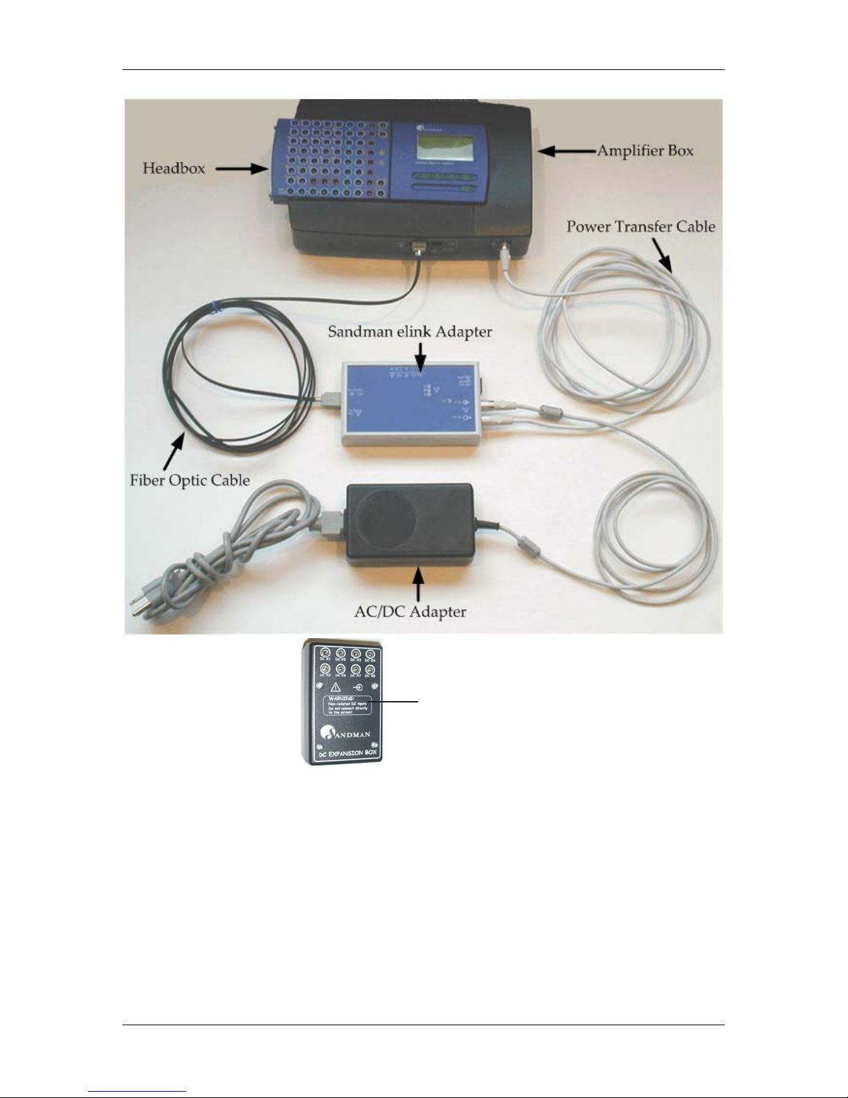
The SD32+ system consists of seven key components: the Headbox, Amplifier, Headbox to
Amplifier Cable, Sandman elink Adapter, pulse oximetry sensor, External Medical Grade AC/DC
Adapter, and the DC expansion box. These components can be seen in Figure 1. the SD32+ system.
The Headbox provides an electrical connection between the patient and the SD32+ amplifier
using electrodes.
The Headbox to Amplifier Cable allows the Headbox to function without being physically
mounted to the SD32+ amplifier allowing for greater flexibility in lab setups.
The Sandman elink Adapter receives optical digital data from the SD32+ amplifier and converts it
for transmission over an Ethernet network to relay it to the computer running the Sandman Elite
software. The SD32+ amplifier communicates with the Sandman elink Adapter via fiber optic
cable.
The External Medical Grade AC/DC Adapter (“AC/DC Adapter”) provides an isolated +15V
direct current (DC) voltage to the SD32+ amplifier through the Sandman elink. The +15V DC
output is electrically isolated from the AC supply mains using methods compliant with the
International Electrotechnical Commission’s (IEC) safety standard IEC 601-1 for Class I, type B
equipment. The AC/DC Adapter is plugged into an Uninterruptible Power Supply (UPS); which,
in turn, is plugged into an electrical outlet. The UPS is used to prevent undesirable effects of the
electrical system such as electrical noise; power outages, sags, or surges; etc. from adversely
affecting the performance of the SD32+ system.
The SD32+ amplifier’s internal Pulse Oximeter receives data from a finger probe attached to the
patient. This data is then sent to the Sandman elink Adapter; which passes it on to the computer
running the Sandman Elite software.
The DC expansion box accepts analog input signals from a variety of DC devices (e.g. CPAP or
pressure) and sends their signals directly to the computer running the Sandman Elite software.
®
Digital 32+
™ amplifier (
®
software (version 7.2 or greater) and the Sandman
SD32+
)
10
Page 15
SD32+
System Introduction
DC Expansion B ox
Figure 1. the SD32+ system
3.2. headbox
Patient electrodes and sensors plug into the SD32+ amplifier headbox. There are 68 input sockets
that accept 1.5-mm electrode safety plugs including 32 AC monopolar input sockets, 8 pairs of
AC bipolar input sockets, 3 neutral input sockets, 13 isolated ground input sockets, 2 temperature
input sockets, and 2 calibration signal output sockets.
connectors
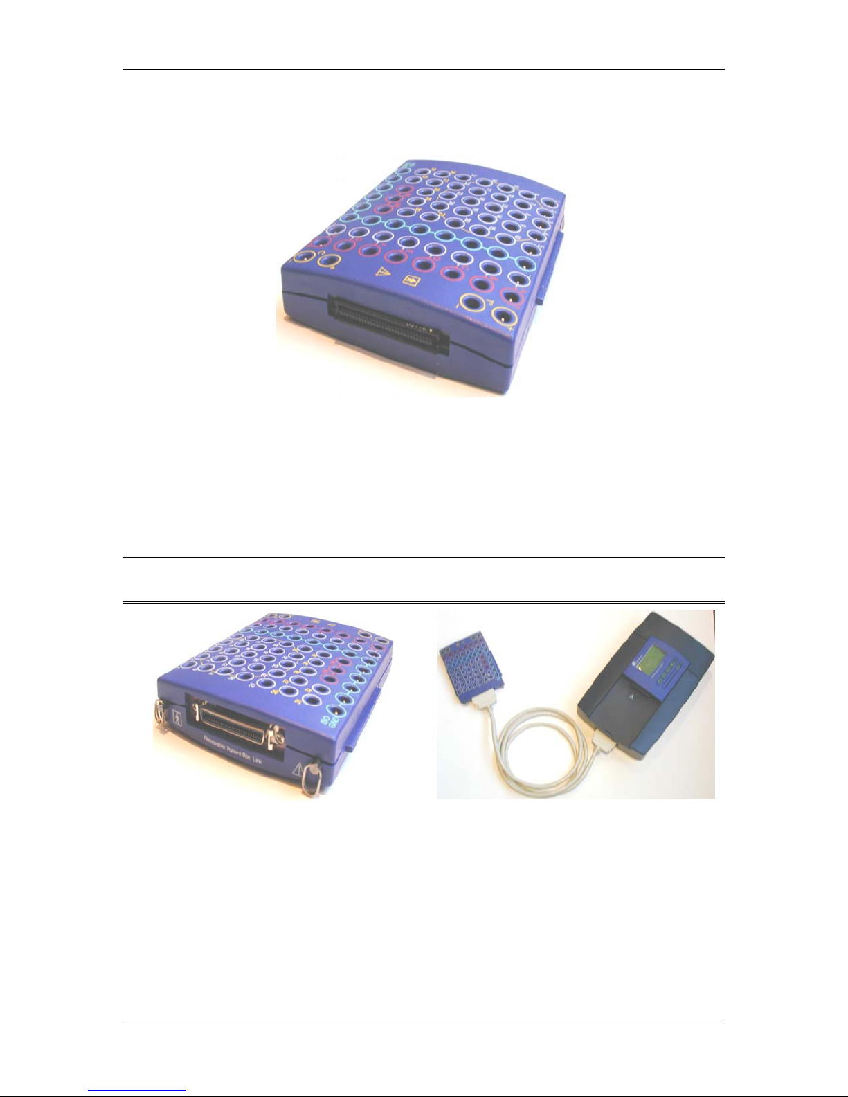
The Headbox has two different ports that can be used to interface with the SD32+ amplifier.
11
Page 16
Introduction
Amplifier Connection Port – This port allows the Headbox to be physically connected to the
amplifier (this process is referred to as “docking” the Headbox). See Figure 2. the headbox amplifier
connection port for an illustration of this port.
Figure 2. the headbox amplifier connection port
Removable Patient Box (Headbox) Link Port – This port connects the Headbox to the amplifier
using the six-foot Headbox to Amplifier Cable. The cable allows users to place the Headbox near
the patient and allows the patient to be easily disconnected from the amplifier without having to
remove electrodes from the patient. The cable should be kept clear of other devices or cables in
order to achieve the best signal performance. See Figure 3. removable patient box (headbox) link for
an illustration of this port. See Figure 4. headbox to amplifier cable for an illustration of this cable.
SD32+
System
Note: When the Headbox’s Removable Patient Box Link port is not in use replace the plastic
cover provided with the SD32+ amplifier to prevent dust build-up on this connector.
Figure 3. removable patient box (headbox) link
port
Figure 4. headbox to amplifier cable
electrode sockets
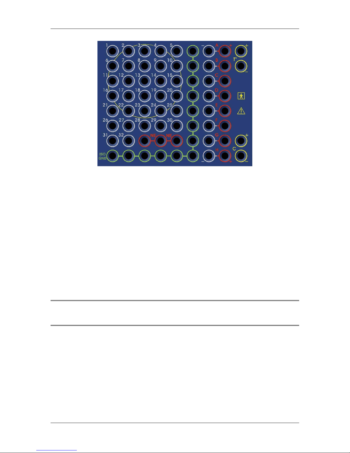
The Headbox has six types of electrode sockets: Monopolar, Bipolar, Neutral (NE), Isolated
Ground (ISO GND), Temperature, and Calibration. Figure 5. headbox electrode sockets displays the
Headbox’s general appearance and the layout of the electrode sockets.
12
Page 17
SD32+
System Introduction
Figure 5. headbox electrode sockets
Monopolar Input Sockets – These input sockets, labeled with numbers ranging from “1” to “32”,
accept monopolar signals from the patient. The amplified signal is the difference in potential
between a monopolar input socket and its reference electrode socket. Channels collected using
these input sockets may be referenced to the Neutral (NE) input sockets.
Bipolar Input Sockets – These input sockets, labeled with letters ranging from “A” to “H”,
accept inputs from bipolar monitoring devices such as a respiratory belt, snore microphone,
thermocouple, or any device with a bipolar output. The amplified signal is the difference of
potential between the “+” and “–” connection.
Neutral (NE) Sockets – These sockets accept monopolar analog signals and may be used as an
input reference for sites plugged into the sockets labeled “1” to “32” (i.e. they may be used to
accept a general reference input such as CZ for numbered AC channel inputs). There are three
parallel neutral input sockets on the Headbox labeled “NE”. This is also used as the reference
when impedance testing is done.
Isolated Ground (ISO GND) Sockets – These sockets, labeled “ISO GND”, accept and isolate the
patient ground to prevent leakage current from making a direct path to the patient. The 13
Isolated Ground input sockets connect the patient to ground.
Warning: The output from any DC device plugged directly into the Headbox must provide
an electrically isolated signal. Do not plug a non-isolated DC signal into the
Headbox as this compromises patient safety.
Temperature Sockets – These two sockets, labeled “T°”, accept input from an external
temperature probe. These input sockets are disabled if you have connected the Headbox to the
amplifier with the Headbox to Amplifier Cable.
Calibration Sockets – When these two sockets, labeled “C”, are enabled, they output the
amplifier’s calibration signal. You can connect the signal to any input (including the lead used for
the connection) for testing. These sockets are disabled if the Headbox is connected to the
amplifier with the Headbox to Amplifier Cable.
13
Page 18

Introduction
SD32+
The following table summarizes the Headbox electrode sockets and their characteristics:
input socket
label
A - H Bi-polar AC Accepts channel signal
1 - 24 Mono-polar AC Accepts channel signal
25 - 32 Mono-polar AC/DC Accepts channel signal
socket type current
type
function Gain setting +
input and reference
input
input
resolution
‘High’
1 µV/8 bits
‘Low’
2 µV/bit
‘High’
1 µV/8 bits
‘Low’
2 µV/bit
‘High’
1 µV/8 bits
‘Low’
2 µV/bit
‘DC1’
10 µV/bit
‘DC2’
20 µV/bit
‘DC23’
100 µV/bit
Max. input
8mV
128mV
8mV
128mV
8mV
128mV
640mV
1.28 V
6.4 V
System
p-p
p-p
p-p
p-p
p-p
1
p-p
2
p-p
3
p-p
4
p-p
Neutral (NE) N/A N/A References mono-
polar channel inputs
Isolated Ground
(ISO GND)
To
(Temperature)
N/A N/A Connects patient
ground
Bi-polar DC Accepts a temperature
probe input when the
Headbox is docked
C (Calibration) Bi-polar AC Generates calibration
pulse output when the
Headbox is docked
Table 4. SD32+ amplifier headbox sockets
1
Includes 28 mV
2
Includes 140 mV
3
Includes 280 mV
4
Includes 1.4 V
p-p
p-p
offset
offset
p-p
offset
p-p
offset
14
Page 19
SD32+
System Introduction
3.3. amplifier
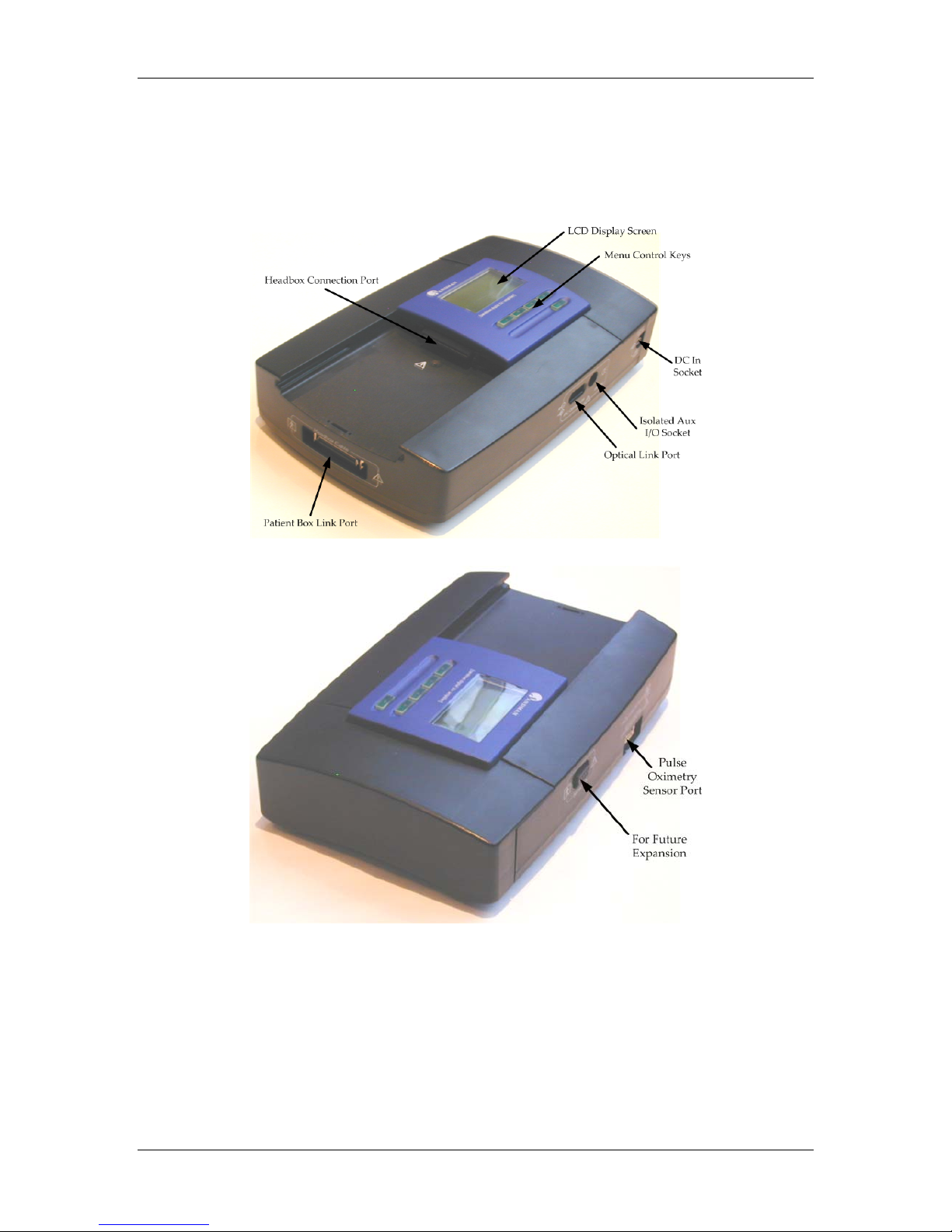
The SD32+ amplifier has two sockets, five ports, a graphic LCD display, and five menu control
buttons as illustrated in Figure 6. SD32+ amplifier’s external connections (front) and Figure 7. SD32+
amplifier’s external connections (back).
Figure 6. SD32+ amplifier’s external connections (front)
Figure 7. SD32+ amplifier’s external connections (back)
15
Page 20

Introduction
SD32+
System
ports
Headbox Connection Port – This port connects the Headbox directly to the amplifier when the
Headbox is “docked”.
Patient Box Link Port – This port connects the Headbox to the amplifier when using the
Headbox to Amplifier Cable.
Note: When the Patient Box Link port is not in use replace the plastic cover provided to
prevent dust build up on this connector.
Optical Link Port – This port connects the amplifier to the Sandman elink Adapter using a fiber
optic cable.
Pulse Oximetry Sensor Port – This port accepts signals from an external finger probe and sends
them to the internal pulse oximeter.
Warning: Always use sensors that have been approved by Embla Systems. Sensors must also
be cleared for commercial use in your jurisdiction. The oximeter does not possess
alarm management capabilities and is not intended for continuous patient
monitoring.
Serial I/O Port – This port is reserved for future development.
sockets
DC In Socket – This socket accepts the 15V direct current (DC) voltage from the AC/DC
Adapter.
Warning: The DC In socket is only designed for use with the External Medical Grade
AC/DC Adapter provided with the SD32+ amplifier. Do not connect anything else
to this socket.
Isolated Aux I/O – This socket is reserved for future development.
Warning: Do not connect any device to the Isolated Aux I/O socket that has not been
specified as safe by Embla Systems. Such an action may compromise the safety of
the operator and/or patient.
16
Page 21

SD32+
System Introduction
3.4. LCD display
The LCD screen allows the user to assess the patient hook-up without having to view signals in
the control room.
The Sandman Elite software controls the LCD screen and determines the information that it will
display. With the exception of the impedance check, the LCD display does not control any of the
amplifier’s functions.
The screen initially appears blank, but lights up and displays information when you press one of
the Menu Control Keys (see Figure 6. SD32+ amplifier’s external connections (front) for the location
of these buttons). The display then indicates the amplifier’s “ON” status and the result of the
internal auto test after powering up. The screen powers down again twenty seconds after the last
button is pressed.
After a montage in the Sandman Elite software has been selected, the LCD screen provides the
following menu options: Impedance Check, Montage Setup, Digital Display, and Channel
Display.
The LCD’s Menu Control Keys allow users to select different menu options and thereby choose
the information that will be displayed. Once the screen is activated, the Menu Control Keys
function as follows.
The up S and down T buttons allow users to select an option from the main menu. An arrow
along the left side of the screen points to the various options. Press the Enter button to select an
option.
The left W and right X buttons allow users to scroll through the displayed information. For
example, during Channel Display, use the right button to skip to the next channel in the montage.
Use the left button to go back to the previous channel viewed. Press the Enter button to return to
the main menu at any time.
impedance check menu option
This menu option sets the amplifier in impedance check mode and displays the channel number,
name, and impedance value in kOhms (kΩ) on the LCD screen. Scroll through the channels using
the up S and down T buttons. Press the Enter button to stop the impedance check at any time.
Note: If the LCD screen has dimmed accurate impedance values will no longer be read.
montage setup menu option
This option allows users to verify channel connections while connecting electrodes. The LCD
screen displays the amplifier connector ID and channel name. The information is updated each
time the menu control button is pressed.
digital display menu option
This option allows users to navigate through the DC channels and verify their current signal
value. Digital Display works with the following channel types: SpO
CPAP, Bi-Level, pH, EtCO
, EtO2, NPT, TcpO2, TcpCO2, PES, Pulse Amplitude, Pleth, and Other.
2
, Pulse, Body Position,
2
The Sandman Elite software updates the LCD screen every second by sending it the channel ID,
name, and current value.
17
Page 22

Introduction
SD32+
System
channel display menu option
This option displays the waveform of a channel’s signal on the LCD screen. The Channel Display
option works with the following channel types: Airflow, Chest, Abdomen, Nasal Cannula,
Airflow Sum, EtCO
, PES, Pulse Amplitude, Pleth, and Other. The signal is automatically scaled
2
to fit the 128 by 68 pixel display screen. The waveform “wraps around” the display so that when
it reaches the far right side of the display drawing resumes on the left overwriting the previously
drawn signal. The channel label initially appears in the background, but is eventually overwritten
by the signal as it is drawn. Scroll through the channels using the up S and down T menu
control buttons.
Note: The SD32+ does not store collection data, therefore, the LCD screen can only display
signal waveforms during a Sandman Elite Collection.
3.5. integrated pulse oximeter
The integrated pulse oximeter calculates oxygen saturation (SpO2) and heart rate (HR) data
collected using an approved sensor. The Sandman Elite software receives this data and displays it
on the computer monitor.
The pulse oximeter’s accuracy depends on the sensor used with the device. For some sensors, the
accuracy of neonatal data may differ from that of adult data.
The following conditions can also affect data accuracy.
• Improper sensor application
• Excessive patient movement
• Sensor placement on an extremity that has a blood pressure cuff, arterial catheter, or
intravascular line
• Intravascular dye injections
• Significant concentrations of dysfunctional hemoglobin, such as carboxyhemoglobin and
methemoglobin in the patient’s blood
• Sensor temperature (maintain between 28°C and 42°C for best operation)
2
• External illumination greater than 5000 lumens/m
(typical office lighting)
• Venous pulsation
• High-frequency electrical noise, including electrosurgical equipment and defibrillators
• Interference from magnetic resonance imaging (MRI) procedures
18
Page 23
SD32+
System Introduction
3.6.
Sandman elink™
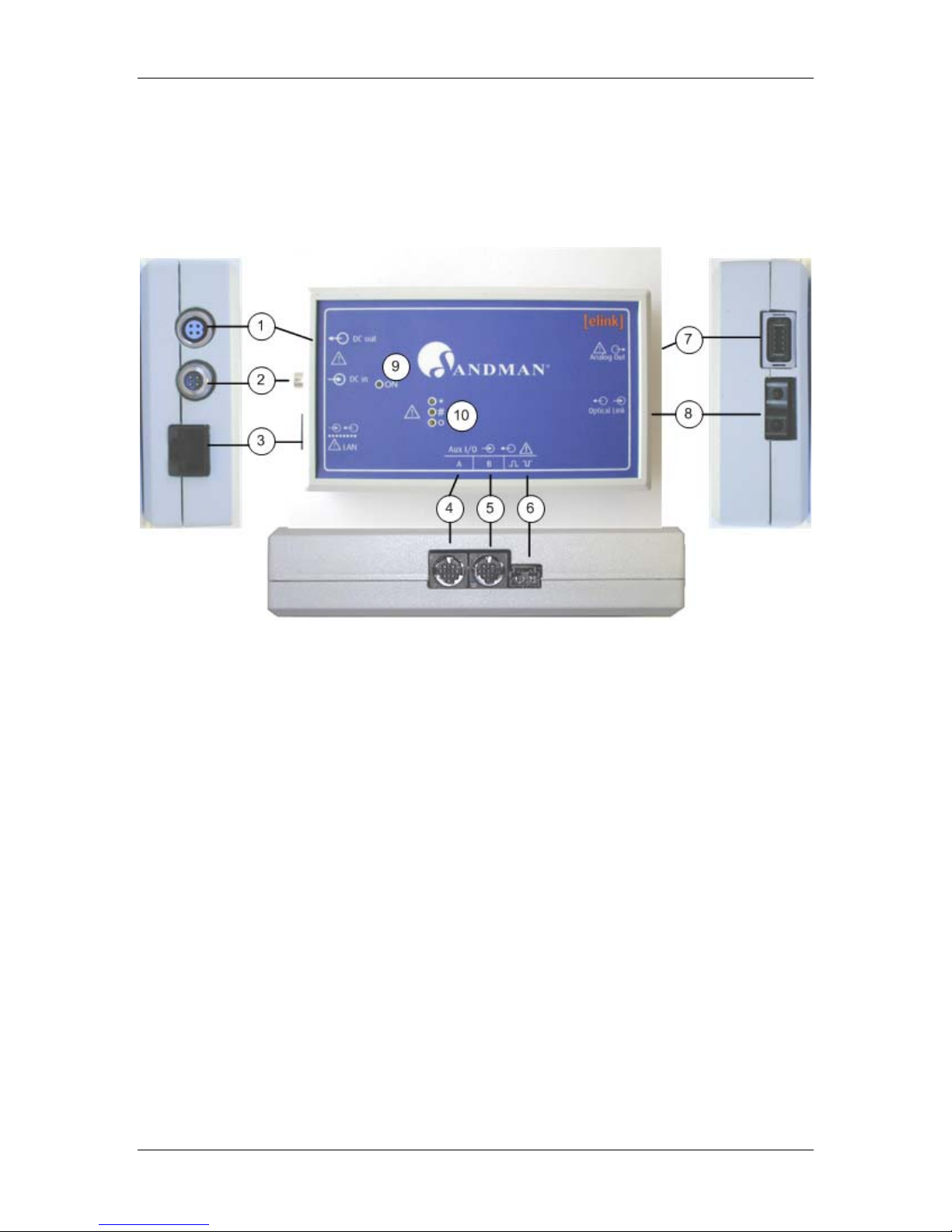
The Sandman elink adapter serves as a bridge to “link” the SD32+ amplifier to the computer. This
enables the computer to send programming commands to, and receive sleep study data from, the
SD32+ amplifier.
The following figures show the Sandman elink adapter:
adapter
Figure 8. Sandman elink adapter
1. DC OUT - (Circular, 4 contact, Female, Triad connector). Supplies the SD32+ amplifier
with DC voltage.
2. DC IN - (Circular, 4 contact, Male, Triad connector). Isolated DC input Connector; accepts
the DC voltage output from the External Medical Grade AC/DC Adapter.
3. LAN - (RJ45 connector) Local Area Network, 10/100 Mbps Ethernet interface.
4. Serial AUX I/O - (A) - (Circular, 8 contact, Female, HiRose connector). Connects to
peripheral devices using the RS232 communications protocol. Only use devices approved
by Embla Systems for use with the Sandman elink adapter.
5. Serial AUX I/O (B) - Same as “Serial AUX I/O – (A)” above.
6. Trigger I/O - Reserved for future use.
7. Analog out Link - Reserved for future use.
8. OPTICAL LINK – (Dual-strand fiber optic connector) Used to communicate with the
SD32+ amplifier.
9. Power on LED - Power status indicator.
10. LAN activity LEDs - Indicate various LAN states.
19
Page 24
Introduction
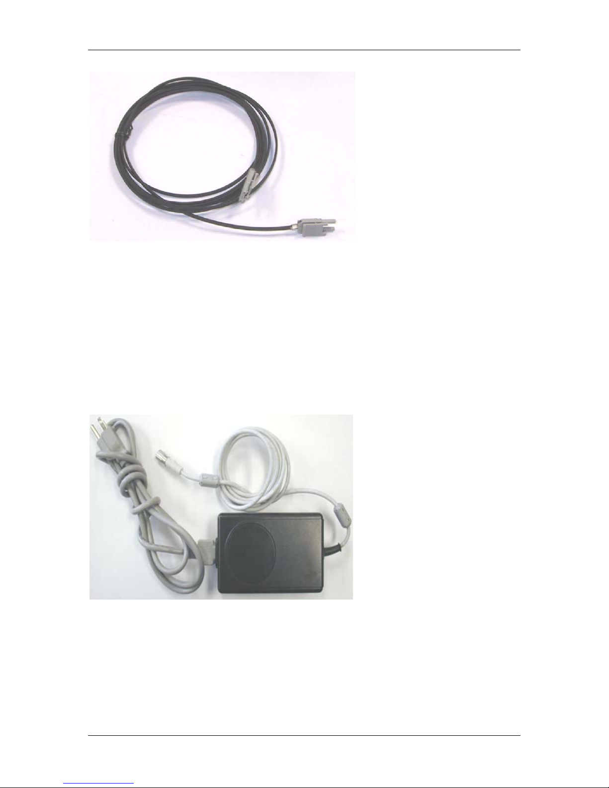
Figure 9. fiber optic cable
Communications between the SD32+ amplifier and the Sandman elink adapter occur using a bidirectional fiber optic cable. This optical link guarantees an absolute level of electrical isolation
and offers high quality data transfers that are free of noise and electrical interference.
SD32+
System
3.7. power supply
3.7.1. external medical grade ac/dc adapter
Figure 10 shows the AC/DC Adapter that is specified for use with the Sandman elink adapter and,
in turn, the SD32+ system. When connected to the Sandman elink adapter’s “DC In” socket, power
from this device is passed to the SD32+ amplifier via the “DC Out” connector using the Power
Transfer Cable (see Figure 11).
Figure 10. external medical grade ac/dc adapter
20
Page 25

SD32+
System Introduction
Figure 11. power transfer cable
3.7.2. amplifier power modes
The Sandman Elite software can control the SD32+ amplifier power modes. When power is
applied to the DC In socket of the amplifier, it automatically enters “stand-by” mode. In this
mode, all internal circuitry is switched off except for a simple circuit that monitors the state of the
Optical Link Port.
When the computer is started, it automatically sends a light signal through the fiber optic
connection. This signal causes the amplifier to enter its “active” or “on” mode, immediately
perform an auto test, and display the test results on the LCD screen. To completely turn off the
amplifier you can either remove the Power Transfer Cable from the DC In socket or unplug the
AC/DC Adapter from the wall outlet (this will power down the elink causing it to stop providing
power to the SD32+ amplifier).
There is an easy check to test the amplifier without involving the computer. Press and hold one of
the five Menu Control Keys until the amplifier enters “active” mode and performs the auto test.
See section 3.4. LCD display on page 17 for more information on these buttons.
3.7.3. surge protection
The AC/DC Adapter used with the SD32+ system contains an electronic fuse that may
automatically turn off the amplifier if a power surge occurs. If the Sandman elink Adapter does
not power up when connected to the AC/DC Adapter, a surge may have triggered this fuse and
it will need to be reset.
To reset the fuse:
1. Unplug the AC/DC Adapter from the wall socket.
2. Wait approximately one minute.
3. Plug the adapter back into the wall socket.
After you reset the fuse the Sandman elink Adapter should power up normally, if it does not, reset
the fuse again. If after repeated resets the Sandman elink still does not power up you should
contact Embla Technical Support for assistance.
3.8. DC expansion box
The DC expansion box provides supplemental DC input sockets in addition to the DC-capable
input sockets labeled “25” to “32” on the SD32+ amplifier headbox. To ensure the patient’s
electrical isolation, the DC expansion box does not connect to the SD32+ amplifier. Instead, it is
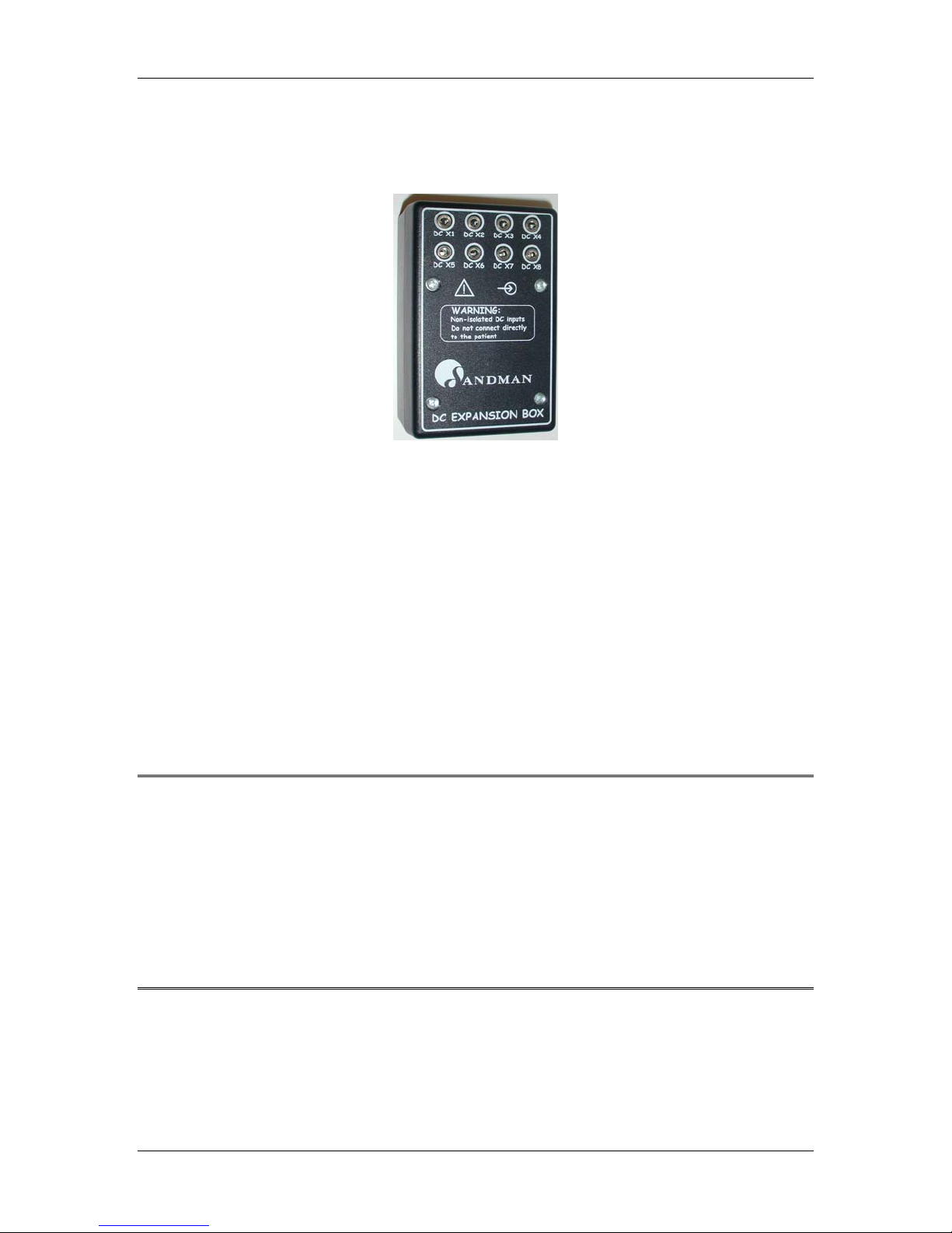
located in the control room and sends collected signals directly to the computer. See Figure 12. dc
expansion box input sockets, for an illustration of the sockets available.
Though the amplifier and the DC expansion box are not directly connected, the Sandman Elite
software can collect signals from both units at the same time in a single montage and store them
21
Page 26
Introduction
in a single patient file. To add the DC expansion channels to a montage, click the Add button in
the Edit Montage window and select the appropriate socket number from the input label dropdown list. The input labels available in the drop-down list correspond to the input socket labels
on the expansion box.
Figure 12. dc expansion box input sockets
SD32+
System
inputs
DC X Inputs – These inputs, ranging from “DC X1” to “DC X8” accept analog signal inputs from
any DC device equipped with an analog output. The connector used to input a DC signal into a
DCX socket is a 1/8” male mono connector. The eight input sockets allow the unit to accept DC
inputs from multiple beds simultaneously. For example, the Sandman Elite software could be
programmed so that sockets “DC X1” to “DC X4” accept inputs from bed one DC devices and
sockets “DC X5” to “DC X8” accept inputs from bed two DC devices. The socket assignments on
your expansion box were set up according to your lab’s needs during installation. Only the
sockets that have been assigned to the current bed appear in the list of channels that can be added
to the montage.
ports
J2 Serial port – This port sends the collected signals to the COM port of the computer running the
Sandman Elite software.
Warnings: The DC expansion box may only be used outside of the “Patient Area” (as defined
in the IEC 601-1-1 safety standard). The connections on the DC expansion box are
not isolated from the ground of your building’s electrical system. Do not allow
these connections to come into contact with either the patient or any isolated input
of the SD32+ system as this will compromise patient safety.
All equipment connected to the DC expansion box must be certified under the
medical requirements of IEC 60601-1 deemed applicable by local authorities.
Body position sensors should be used with the DC Expansion box and not directly
connected to the SD32+ amplifier.
22
Page 27

SD32+
System Software Driver Installation
4. Software Driver Installation
To install the SD32+ amplifier, you must have a Microsoft® Windows® operating system installed
on your computer that is compatible with the Sandman Elite software. For more information
about supported operating systems, consult your Sandman Elite User Manual.
In most cases, a qualified representative from Embla Systems will install your amplifier and
device drivers. If you need assistance, please contact Embla Technical Support.
23
Page 28

Amplifier System Assembly
SD32+
5. Amplifier System Assembly
5.1. connecting the headbox to the amplifier
You can connect the Headbox to the amplifier either directly or by using the Headbox to
amplifier Cable.
Direct Headbox Connection
To connect the Headbox directly to the amplifier:
1. Slide the Headbox firmly into the headbox platform on the top of the amplifier
casing.
2. Ensure that the Headbox Connection port on the amplifier and the Headbox
Amplifier Connection port on the Headbox are fully connected. The Headbox
should be flush against the LCD display and menu control area.
Remote Headbox Connection
To connect the Headbox to the amplifier using the Headbox to Amplifier Cable:
1. Press the release button beneath the portion of the Headbox that extends over the
end of the amplifier and slide the Headbox away from the LCD until it is free of the
amplifier casing.
2. Connect one end of the Headbox to Amplifier Cable to the Patient Box Link port on
the amplifier.
3. Connect the other end of the Headbox to Amplifier Cable to the Removable Patient
Box Link port on the Headbox.
System
5.2. connecting the amplifier to the
To connect the amplifier to the Sandman elink Adapter:
1. Insert one end of the fiber optic cable into the Optical Link port on the amplifier
until you hear or feel it click into place; the plug will only fit into the port one way.
2. Insert the opposite end of the fiber optic cable into the Optical Link connector on the
Sandman elink Adapter until you hear or feel it click into place; the plug will only fit
into the port one way.
sandman elink
adapter
5.3. connecting the external power supply to the amplifier system
To provide the SD32+ system with power:
1. Screw the AC/DC Adapter’s DC input plug into the DC In socket on the Sandman
elink Adapter.
2. Screw the appropriate end of the Power Transfer Cable into the DC Out socket on
the Sandman elink Adapter.
3. Screw the opposite end of the Power Transfer Cable into the DC In socket of the
amplifier.
4. Insert the power cord into the three-pronged plug of the AC/DC Adapter.
5. When you are ready to start collecting data, plug the AC/DC power cord into a wall
outlet.
24
Page 29

SD32+
System Amplifier System Assembly
5.4. connecting the DC expansion box to the computer (serial
connection)
To connect the DC expansion box to the SD32+ system using the serial connection:
1. Ensure that the computer is off.
2. Insert plug A of the SD32+ amplifier DC Expansion Box Cable into the J2 Serial port
on the DC expansion box. See Figure 13. SD32+ amplifier dc expansion box cable for
details.
Figure 13. SD32+ amplifier dc expansion box cable
3. Insert plug B of the SD32+ amplifier DC Expansion Box Cable into the COM port on
the computer.
4. Disconnect the mouse or keyboard from its port on the computer.
5. Insert plug C of the SD32+ amplifier DC Expansion Box Cable into mouse or
keyboard port on the computer.
6. Plug the mouse or keyboard PS2 plug into socket D of the SD32+ amplifier DC
Expansion Box Cable.
Changes must also be made to the Sandman software configuration so that the software can detect
the DC expansion box. Please contact Embla Technical Support.
5.5. connecting the DC expansion box to the computer (USB
connection)
To connect the DC expansion box to the SD32+ system using the USB connection:
1. Ensure that the computer is off.
2. Plug the small connector of the USB cable into the J2-USB port on the DC expansion box.
3. Plug the large connector of the USB cable into the USB port on the computer.
When you turn on the computer, the operating system will recognize the DC expansion box.
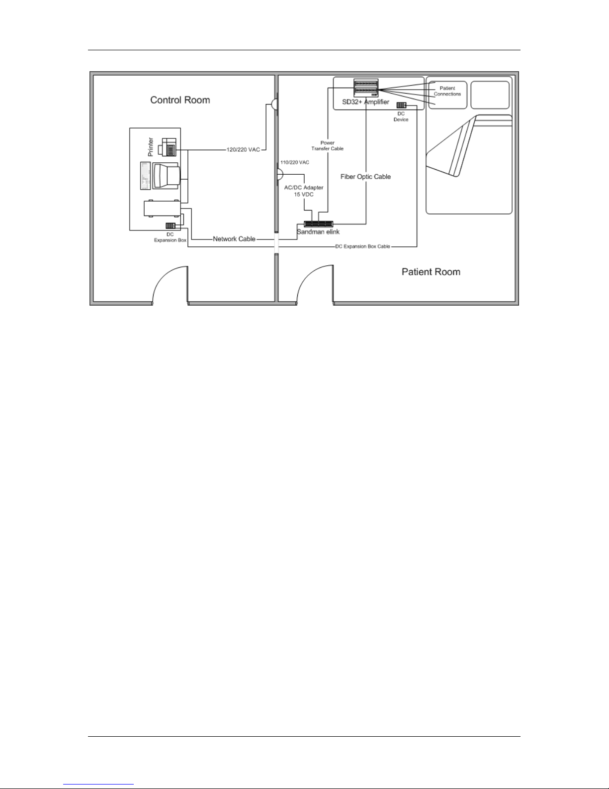
See Figure 14. typical SD32+ system set-up on page 26 for an illustration of a typical lab setup.
25
Page 30
Amplifier System Assembly
Figure 14. typical SD32+ system set-up
SD32+
System
26
Page 31

SD32+
System Calibration
6. Calibration
6.1. system record calibration
System record calibration is performed at the beginning and at the end of every study. Under the
control of the Sandman Elite software, the amplifier generates a standard 50μV square-wave signal
for calibration. This calibration is important for verifying filter and gain settings and for setting
reference levels in a data record.
27
Page 32

Maintenance
SD32+
System
7. Maintenance
To ensure that the SD32+ amplifier operates properly and effectively, ensure that the signals are
calibrated, the cables and connectors are in good shape, and the equipment is cleaned on a
regular basis.
7.1. safety checks
Periodically check the SD32+ amplifier, and all devices connected to it, to ensure continued
efficiency and safety. Testing should include electrical leakage tests and should be performed at
least twice yearly by qualified biomedical personnel. Additionally, check the SD32+ system for
any dust deposits.
Perform a visual inspection of all connection cables and power cords for any signs of breakage or
improper connection. If such problems exist, contact a qualified representative at Embla Systems.
Note: Safety checks should be performed periodically and no less than twice a year.
7.2. operational environment electrical equipment
Inspection of the electrical wiring of the AC supply mains should be conducted periodically to
ensure proper grounding is available in the operating environment of the SD32+ system.
7.3. amplifier calibration
Semi-annually: Check the amplifier at various gain and filter settings. Verify the amplitude and
frequency characteristics of the resulting waveforms. It is recommended that each filter and gain
level be tested.
7.4. cables and connectors
Periodically check the integrity of all connection cables used with the SD32+ system, particularly
the fiber optic cable. Remove the cables from their sockets and ports carefully. Twisting or
pulling on the cables instead of their connectors may cause breaks or short circuits.
Monthly: Check cables monthly for abrasion and wear. Replace any cable with exposed wires or
shielding (wire mesh located just below the outer casing of a cable).
Check the connectors on the ends of the cables for bent or broken pins. Replace any cable that has
a damaged connector.
Check the connectors on the amplifier, headbox, and Sandman elink Adapter for broken or
damaged contacts. If any are found, return the unit to Embla Technical Support for servicing or
replacement.
28
Page 33

SD32+
System Maintenance
7.5. cleaning
Monthly: Clean the amplifier’s external surface with a cloth lightly moistened with warm water
and soap. Wipe the washed parts with a dry cloth.
Warnings: Before cleaning any part of the amplifier, disconnect it from any source of power
and from any external devices.
Ensure that no liquid enters the amplifier and that it is completely dry before
attempting to apply power to it or before connecting it with other devices.
Caution: Do not immerse the amplifier or its parts in liquids. Do not oil any part of the
amplifier. Additionally, avoid cleaning the external surface with alcohol-based
disinfectants as they may cause discoloration or damage the labeling.
To obtain maintenance or cleaning information for equipment connected to the SD32+ that is not
produced by Embla Systems, such as sensors, computers, monitors, printers, or other accessories,
consult the manual supplied with the equipment.
29
Page 34

Specifications
8. Specifications
8.1. system specifications
Description Active, non-invasive, medical device.
Intended Use Amplifier Module for the acquisition (capture,
conditioning, A/D conversion and transferring to a host
system) of bioelectric signals produced by the human
body
SD32+
System
Classification According to
MDD 93/42/EEC
Safety Standard 93/42/EEC European Medical Device Directive
Type of Protection Against Electric
Shocks
Protection Level Against Direct and
Indirect Electrical Contacts
Class II b
(MDD)
IEC 60601-1 General safety standard for
electromedical equipment
IEC 60601-1-1 Collateral safety standard for
electromedical systems
IEC 60601-1-2 Collateral safety standard for device
EMC test
IEC 60601-1-4 Safety standard for devices containing
programmable systems
IEC 60601-2-26 Standard on particular safety
requirements for
electroencephalographs
Class I equipment powered by specified power supply
BF type (patient input)
Protection Level Against Inflow of
Solids and Liquids
30
IPX0
Page 35

SD32+
System Specifications
8.2. environmental operating conditions
Temperature +5 °C to +40 °C
Relative Humidity 30% to 75% RH
Atmospheric Pressure 700 hPa to1060 hPa
8.3. environmental conditions for storage
Storage Temperature -30 °C to +60 °C
Relative Humidity 5% to 95% RH (excluding condensation)
Atmospheric Pressure 500 hPa to 1060 hPa
8.4. amplifier specifications
8.4.1. general amplifier specifications
Part Number 4200022
Operating Channels 24/32/40
EEG/Polygraphic Channel 40
DC Channel up to 8
Impedance Measurement
A/D Conversion 2’s complement 24 bit Sigma-Delta A/D (16 bits actually
Amplifier – PC Interface Sandman elink Adapter (by means of a fiber optic link)
Other Interfaces 128x64 graphic LCD display and 5 push buttons
Power Supply External IEC 601-1 Class 1, type B, AC/DC adapter
Power Consumption 900 mA typical (40 channels)
Case ABS Plastic
Dimension 250 x 170 x 65 mm
Weight 1.5 kg
By means of injected current (20Hz - 0.01μA per
electrode)
transferred to host)
Isolation Fiber optic link
31
Page 36

Specifications
μ
SD32+
System
8.4.2. filters
High-Pass Filters Channels A to H and 1 to 32 Either DC or 0.099 Hz first order filter
Low-Pass Filters
Frequency cutoff at -3dB: 0.488 x sampling rate
(A/D Converter
Output)
Attenuation
at -6dB: 0.500 x sampling rate
80 dB f ≥ 0.55 x sampling rate
8.4.3. resolution, full scale range, noise
channels A to H and channels 1 to 24
High Low
Gain Setting / Resolution
Full Scale Range 8 mV
Noise (0.1 Hz - 70 Hz)
channels 25 to 32
High Low DC1 DC2 DC3
Gain Setting /
Resolution
Full Scale
Range
Noise
(0.1 Hz - 70 Hz)
1/8 μV/bit 2 μV/bit 10 μV/bit 20 μV/bit 100 μV/bit
8 mV
p-p
≤ 1.5
V
p-p
max
≤ 0.5 μVrms
1/8 μV/bit 2 μV/bit
p-p
max 20 μV
p-p
5
640 mV
p-p
p-p
≤ 200 μV
p-p
p-p
6
max
1.5 μV
128 mV
≤ 20 μV
max
128 mV
1.28 V
p-p
≤ 500 μV
max
p-p
7
p-p
p-p
max
6.4 V
≤ 1 mV
max
p-p
p-p
8
5
Includes 28 mV
6
Includes 140 mV
7
Includes 280 mV
8
Includes 1.4 V
32
p-p
p-p
offset
offset
p-p
offset
p-p
offset
Page 37

SD32+
System Specifications
8.4.4. sampling rate
max sampling rate
Number of Simultaneously Acquired
Channels Maximum Sampling Rate
1 to 16 32768 Hz
16 to 32 16384 Hz
32 to 40 8192 Hz
Selectable Sampling Rate 128,256,512… 32768 Hz (according to the limit of the
maximum sampling rate)
sampling skew
All acquired channels will be sampled simultaneously (no sampling skew)
CMRR >100 dB (>95 dB on polygraphic channels)
IMRR >120 dB
Max. DC Offset (AC Mode)
± 300 mV
8.5. headbox specifications
Part Number 4200017
Case ABS Plastic
Dimension 126 x 96 x 25 mm
Electrode Connectors 32 active – one active connection to each input
(monopolar)
16 active – two active connections to each input (bipolar)
3 for neutral electrode
13 for isolated ground electrode
2 for temperature probe input
2 for calibration signal output
Connection to Amplifier Extension
Cable
50 pin Microcentronics male
Shielded cable (max 2m)
33
Page 38

Specifications
SD32+
System
8.6. external medical grade AC/DC adapter specifications
You can use either of the following AC/DC power adapters (D.2101) with the Sandman elink
Adapter:
8.6.1 AULT SW173
Manufacturer AULT inc.
Model SW173
Input 100-240VAC - 50/60Hz
Output 15VDC @ 2.2A
Safety Standards IEC 601-1 (CEI 62-5)
89/336/EEC (EMC)
73/23/EEC (Low Voltage)
Mark CE, TUV, CSA, UL
Electrical protection level Cla ss I, Type B
Case Material: Plastic
Dimensions: 129 x 77 x 40 millimeter
8.6.2 SINPRO MPU50-106
Manufacturer SINPRO Electronics Co., Ltd.
Model MPU50-106
Input 100-240VAC - 47/63Hz
Output 15VDC @ 3A
Safety Standards IEC 601-1 (CEI 62-5)
EN 55011
EN 60601-1-2
Mark CE, TUV, cULus
Electrical protection level Cla ss I, Type B
Case Material: Plastic
Dimensions: 146 x 76 x 43 millimeter
34
Page 39

SD32+
System Specifications
8.7.
Sandman
Part Number 4200036
Case Materials: ABS plastic
Dimensions: 137 x 200 x 8 mm
Weight: 0.2 Kg
Power supply AULT SW173 or SINPRO MPU50-106
Interfaces: HP 100 Mb fiber-optic Transmitter and Receiver
RJ45 for Ethernet 100 bT Network link.
Triad F/M 4+1 per external power supply SW173
MCH Triad - HiRose HR12-10R-8SDL connector for RS232,
Trigger I/O, power supply
QM10-8R-PR HiRose connector for analogical output of digital signals.
Status indicators: Green LED: 3.3 V power is on.
* Yellow LED: Ethernet. Auto-negotiation controller.
# Yellow LED: Ethernet. Link 10 /100 Mb controller.
o Yellow LED: Ethernet. LAN controller.
Device rated values CE0051 mark (93/42/EEC)
®
elink
™ adapter
cCSAus mark
8.8. DC expansion box specifications
8.8.1. technical characteristics
Part Number 4200024
Supply 5V (± 5%) / 0.5 A max
Case Plastic
Dimension 115 x 70 x 45 mm (L x W x H)
Weight 250 g
Inputs 8 x 1/8th inch male mono inputs
Maximum Channel Frequency 64 Hz
Connection to Computer Serial or USB
Number of Analog Inputs 8
Analog Input Signal Range ±5 V ( DC to 16 Hz )
Sampling Rate 8, 16, 32, 64 samples/second – host selectable
Input Impedance > 100 kOhms
A/D Conversion 12 bits
35
Page 40

Specifications
SD32+
8.8.2. environmental conditions
Usage Temperature +5 °C to +40 °C
Relative Humidity 30% / 75% RH
Atmospheric Pressure 700 / 1060 hPa
Storage Temperature -30 °C to +60 °C (relative humidity up to 95% non-
condensing Pressure 500 / 1060 hPa) Max 15 weeks
8.9. pulse oximeter performance
Measurement Range
SpO2 1% to 100%
Pulse Rate 0 and 20 BPM to 250 BPM
Perfusion Range 0.03% to 20%
Accuracy and Motion Tolerance
System
Saturation
Without Motion – Adults
Without Motion – Neonate
With Motion – Adults and
Neonates
Low Perfusion
10
11
5
70 to 100% ± 2 digits
70 to 100% ± 3 digits
70 to 100% ± 2 digits
70 to 100% ± 2 digits
9
Averaging Time Changes in SpO2 are reported in 2-3 seconds
Except as indicated, all accuracies are expressed as ± “X” digits between saturations of 70%–
100%. This variation equals ± one standard deviation (1 SD), which encompasses 68% of the
population. Accuracy specifications are based on controlled hypoxia studies with healthy, nonsmoking adult volunteers over the specified saturation SpO
readings were compared to SaO
values of drawn blood samples measured by hemo
2
The above performance specifications are given for the Nellcor
range. Pulse oximeter SpO2
2
ximetry.
®
OxiMax® sensors. For further
information on Nellcor sensors, please visit www.nellcor.com/prod/index.aspx. A full listing of
all sensors and descriptions can be found here including ordering information.
9
Adult specifications are shown for Nellcor OxiMax MAX-A and MAX-N sensors. Neonate specifications are shown for
Nellcor OxiMax MAX-N sensors. Saturation accuracy will vary by sensor type. Refer to the Sensor Accuracy Grid.
10
Applicability: Nellcor OxiMax MAX-A, MAX-AL, MAX-P, MAX-I, and MAX-N sensors.
11
Specification applies to monitor performance and was validated with Biotek® and Nellcor simulators.
36
Page 41

SD32+
System Index
Index
A
AC/DC adapter · 16
connection · 24
active mode · 21
amplifier
calibration · 27
connection · 24
description · 15
external connections · 15
maintenance · 28
ports · 16
sockets · 16
specifications · 30
amplifier connection port · 11, 24
atmospheric pressure · 6
attention symbol · 2
auto test · 21
B
bipolar sockets · 13
C
cable
DC expansion box · 25
cables and connectors · 28
calibration · 27
signals · 28
sockets · 13
system record · 27
CE mark · 9
channel display · 18
cleaning · 29
computer requirements · 23
condensation · 6
conformity · 9
CSA · 9
E L
extension cable · 12, 24 LCD control buttons · 15
F
fiber optic cable · 24
flammable gases · 6
LCD display · 15
about · 17
channel display · 18
digital display · 17
impedance check · 17
montage setup · 17
safety · 8
leakage current · 8
liquids · 6
G
ground · 1, 6
H
headbox
connection · 24
description · 11
direct connection · 24
extention cable · 24
ports · 11
removable patient box link · 24
sockets · 12
headbox connection port · 16, 24
headbox to amp cable · 12, 16, 24
M
magnetic fields · 6
maintenance · 28
cable and connectors · 28
calibration signals · 28
cleaning · 29
microwave devices · 6
monopolar sockets · 13
montage setup · 17
mouse port · 25
N
NE sockets · 13
neutral sockets · 13
I
impedance check · 17
installation · 24
amplifier · 24
DC expansion box · 25
headbox · 24
power supply · 24
ISO GND sockets · 13
ISO ground sockets · 13
isolated aux I/O socket · 16
O
operational environment · 6
optical link connector · 24
optical link port · 16, 24
P
D
DC expansion box · 21, 25
DC In socket · 16, 24
defibrillator discharge · 7
digital display · 17
J
J2 serial port · 25
patient box link port · 16, 24
patient connection · 8
PC card · 10
port
mouse · 25
power modes · 21
power supply · 20
37
Page 42

Index
SD32+
System
connection · 24
pulse oximeter · 18
accuracy · 18
pulse oximetry sensor port · 16
R
radio frequency instruments · 7
reference sockets · 13
relative humidity · 6
removable patient box link · 24
removable patient box link port ·
12, 24
S
safety
checks · 28
LCD display · 8
leakage current · 8
operational environment · 6
patient connection · 8
Sandman elink Adapter · 10
Sandman Elite software · 10, 17,
18, 27
serial I/O port · 16
short wave devices · 6
symbol · 2, 3
attention · 2
BF protection · 2
input connector · 2
output connector · 2
system record calibration · 27
T
technical support · 21, 23
temperature · 6
sockets · 13
38
Page 43

*4280034*
REF: 4280034
 Loading...