

Page 1

Embla® S4500™
Clinical Manual
Page 2

Embla S4500 Clinical Manual
Copyright © 2008 Embla. All rights reserved.
Issued May 2008
Document #: D-0709-053, Revision 1.0 JLB
Document Item #: 2800107
Embla
11001 W. 120th Ave.
Suite 200
Broomfield, CO 80021
USA
Tel: +1.303.962.1800
Toll-Free: 888.662.7632
Fax: +1.303.962.1810
Kon. Wilhelminaplein 13/2.09.05
1060 CM Amsterdam
P.O. Box 69464
The Netherlands
Tel: +31 20 3460130
Fax: +31 20 3460121
Website:
www.embla.com
Email:
Copyright Notice
No part of this publication may be reproduced, transmitted, transcribed, stored in a retrieval
system, or translated into any language or computer language, in any form, or by any means,
electronic, mechanical, optical, chemical, manual, or otherwise, without the prior written consent
of Embla.
Disclaimer
This document may contain technical inaccuracies or typographical errors. Changes are
periodically made to the information herein; these changes will be incorporated in future
revisions of this document. Embla does not accept any liability for the use or misuse, direct or
indirect, of this product. Users must accept all responsibility for any results obtained by or
concluded from data obtained by the products. The user must accept all responsibility for
results obtained by software from Embla. All clinical conclusions and decisions that are made
based on the use of this product are the responsibility of the user. Embla does not accept any
liability or responsibility for damages arising out of the use of or inability to use this product.
Trademarks
S4500, RemLogic, Somnologica and XactTrace are trademarks of Embla Systems Inc.
REMbrandt and Embla are registered trademarks of Embla Systems Inc. All other trademarks
are the property of their respective owners.
The Embla S4500 is manufactured by Cogent Technologies in the United Kingdom for Embla
Systems Inc.
Printed in the Netherlands.
Page 3

Page 4

i
Contents
About This Manual.........................................................................................1
About the Embla S4500 System.................................................................2
Safety and Regulatory Information...................................................................................................... 2
Warnings, Cautions and Contraindications ............................................3
Warnings and Cautions........................................................................................................................... 3
Intended Use ............................................................................................................................................. 5
Certifications.............................................................................................................................................. 5
Classifications............................................................................................................................................ 6
System Components ......................................................................................7
Communication Unit.................................................................................................................................. 7
About the Communication Unit ........................................................................................................... 7
Rear Panel.............................................................................................................................................. 8
Communication Unit Cables ..............................................................................................................10
Bedside Unit ............................................................................................................................................10
Status Lights.........................................................................................................................................11
Impedance Test Button .......................................................................................................................12
Channel Inputs.....................................................................................................................................12
Cable ....................................................................................................................................................14
Mounting Bracket................................................................................................................................14
Shoulder Strap ....................................................................................................................................15
Sensors......................................................................................................................................................15
Electrodes.............................................................................................................................................15
Sensor Inputs .......................................................................................................................................16
Assembling the System.............................................................................. 18
Mounting the Bedside Unit Bracket.....................................................................................................18
Mounting the Communication Unit .......................................................................................................19
Creating and Attaching an ID Card to the Communication Unit ...................................................20
Connecting the Units...............................................................................................................................21
Connecting the Communication Unit ................................................................................................21
Connecting the Bedside Unit..............................................................................................................22
Installing the System on the Network...............................................................................................24
Connection Types ................................................................................................................................25
Performing a Study ..................................................................................... 27
Study Types.............................................................................................................................................27
Page 5

Embla S4500 Clinical Manual
ii
Attaching the Electrodes........................................................................................................................27
Attaching the Oximeter and Oximeter Flex Sensor ........................................................................30
The Oximeter Sensor..........................................................................................................................31
Attaching the Oximeter Flex Sensor................................................................................................31
Other Oximeter Sensors....................................................................................................................33
Attaching XactTrace Respiratory Effort Sensors ..............................................................................34
Fitting the XactTrace Belt...................................................................................................................34
Attaching the XactTrace Belts to the Patient...................................................................................36
Storing the Belt Lock ..........................................................................................................................37
Considerations for Use.......................................................................................................................37
Attaching the Nasal Pressure Sensor ..................................................................................................40
Attaching the Snoring Sensor ...............................................................................................................42
Attaching the Thermistor........................................................................................................................43
Attaching the Body Position Sensor.....................................................................................................44
Connecting Sensors to the Bedside Unit.............................................................................................45
Testing the Electrode Impedance ........................................................................................................46
Activating the Calibration Test Signal................................................................................................48
During Use................................................................................................................................................48
System Maintenance .................................................................................. 49
Cleaning the System Units.....................................................................................................................49
Cleaning Sensors ....................................................................................................................................49
Single Use Sensors..............................................................................................................................50
Environment..............................................................................................................................................50
Factory Calibration................................................................................................................................51
Disposal....................................................................................................................................................51
Troubleshooting............................................................................................ 52
Problems Starting a Recording............................................................................................................52
Unclear Signals .......................................................................................................................................52
Technical Specifications ............................................................................ 54
Communication Unit................................................................................................................................54
Bedside Unit ............................................................................................................................................55
Bedside Unit Bracket..............................................................................................................................57
Oximeter Accuracy for Type Nonin Xpod.........................................................................................58
Materials List ...........................................................................................................................................59
Further Readings.......................................................................................... 60
List of Tables ................................................................................................. 62
Glossary .......................................................................................................... 63
Page 6

Contents
iii
Index................................................................................................................ 65
Page 7

Page 8

1
About This Manual
This clinical manual is intended for all users of the Embla S4500 system. It is assumed that users
have a basic knowledge of the Windows environment, working with a mouse, using toolbars,
and arranging windows. Sections typically begin with an overview and description of main
features, followed by instructions in simple action steps.
Embla's Knowledge Base contains helpful articles, product information, and information on the
study of sleep. Access this resource at www.embla.com/support/knowbase.
For more information on any Embla product feature, or for technical support, please contact
Embla Technical Support ([email protected]).
Page 9

2
About the Embla S4500 System
The Embla S4500 system is a full polysomnography (PSG) system used to perform online sleep
studies in the sleep lab, hospital or clinical environment, under the supervision of a clinician or
sleep technician.
The Embla S4500 system integrates advanced digital technology and precision engineering
into a flexible, rugged, full polysomnography network. Featuring an Ethernet network
connection, the system is simple to assemble, with cables streamlined for comfort and reliability.
Building on the proven convenience and quality of the Embla S4000 System, the S4500 system
has 13 referential channels, 5 bipolar channels, an extensive set of respiratory data channels
as well as auxiliary inputs and digital serial ports for additional devices such as CPAP and
CO2 machines.
The Embla S4500 system can be used with Rembrandt and RemLogic.
Safety and Regulatory Information
Before using the Embla S4500 system, please read this clinical manual carefully, paying
particular attention to the caution or warning that appears with each safety symbol.
Caution:
The CAUTION notice denotes a potential hazard. It calls attention to an operating
procedure, practice, or the like, which, if not correctly performed or adhered to,
could result in damage to the product or loss of important data. Do not proceed
beyond a CAUTION notice until the indicated conditions are fully understood and
met.
Warning:
The WARNING notice denotes a hazard. It calls attention to a procedure, practice,
or the like, that, if not correctly performed or adhered to, could result in personal
injury. Do not proceed beyond a WARNING notice until the indicated conditions are
fully understood and met.
Page 10

3
Warnings, Cautions and
Contraindications
Warnings and Cautions
The following warnings and cautions are applicable to the Embla S4500:
• The Embla S4500 is NOT TO BE USED FOR CONTINUOUS MONITORING where
failure to operate can cause injuries or death of the patient.
• The system must not be used for direct cardiac application.
• Caution: U.S. Federal law restricts this system to sale by, or on the order of, a
physician.
• No user serviceable parts inside. Serviced by Embla and authorized parties only.
Warranty void if opened.
• The contact of liquids with the internal parts and connectors of the Embla should be
avoided at all times. The system is neither water resistant, drip-proof nor splashproof and the cleaning instructions in this manual need to be strictly adhered to.
• Do not use the Embla S4500 system in an MRI environment.
• Do not use the Embla S4500 device in an explosive environment, that is, in the
presence of flammable liquids or gases.
• The system is not defibrillator proof.
• Caution must be taken to ensure that cables do not encircle the patient's neck.
Special attention is needed in the case of children.
• The Embla S4500 system does not increase the safety risk for pacemaker patients
as long as the pacemakers comply with the EN50061 standard of electrical safety
of medical devices. Nevertheless, it is not advisable to do an impedance test on
pacemaker patients since it might cause the pacemaker to switch to the interference
mode. Prior to using the system with pacemaker patients, the operator should
consult the pacemaker’s accompanying documents regarding its certifications and
requirements of use or, if necessary, contact the producer.
Page 11

Embla S4500 Clinical Manual
4
• Use only with sensors and electrodes provided by Embla or with sensors that have
been validated by Embla. Use of other sensors with this device may impair the
signal quality and device performance. Contact Embla Technical Support
([email protected]) for an updated catalog of sensors and electrodes that may
be used with the device.
• The Embla S4500 complies with the international standard IEC60601-1-2 for
electromagnetic compatibility for medical electrical equipment. This standard is
designed to provide reasonable protection against harmful interference in a
typical medical installation. However, because of the proliferation of radiofrequency transmitting equipment and other sources of electrical noise in healthcare
and other environments, it is possible that high levels of interference due to close
proximity or strength of source might disrupt the device’s performance. For these
reasons, special precaution regarding EMC is needed when the device is installed
and put into service.
• Portable and mobile RF communications can affect the performance of the Embla
S4500 system.
• The Embla S4500 system should not be used adjacent to, or stacked with, other
equipment. If adjacent or stacked use is necessary, the device should be observed
to verify normal operation in the configuration in which it will be used.
• Electrostatic discharges (ESD) may cause artifacts in the signal from the device.
Avoid conditions where electrostatic charge can build up because of low humidity
and friction against carpets, clothing and sheets made from artificial fibers
• The operator must be trained to be able to recognize the difference between a
valid bio-signal and signal artifacts caused by subject movements, RF disturbances
or misplacement of sensors or electrodes.
• Before starting data acquisition with the system, always check the device profile
and patient information in the Embla PSG software application.
• Always inspect the equipment, particularly the cables and connectors, for evidence
of wear before each study. If evidence of wear is found, remove the worn
equipment from use and contact Embla Technical Support ([email protected]) for
replacement or servicing.
Page 12

Warnings, Cautions and Contraindications
5
Intended Use
The Embla S4500 system is intended for use by a physician or trained technician for the
acquisition of Electroencephalogram (EEG) and polysomnography (PSG) signals and their
transmission to a PC during neurophysiologic or sleep examinations. The intended environments
are hospitals, institutions, sleep centers, sleep clinics, or other test environments.
The use of the Embla S4500 system does not involve any patient monitoring or diagnosis.
Certifications
The following certifications are applicable to the Embla S4500:
0413
The Embla S4500 is certified to carry the CE mark. The CE mark is
a declaration that Embla is in compliance with the directive set forth
by the European Union for medical devices.
The ETL mark is a safety symbol which shows that the product has
been independently tested and certified to applicable U.S. and
Canadian product safety standards.
The C-Tick mark indicates that the product complies with the
applicable EMC standard and establishes a traceable link between
the product and the supplier responsible for placing it on the
Australian market.
The Embla Quality Management System complies with EN ISO
9001:2000 and EN ISO 13485:2003.
Embla certifies that the development, manufacture, sales, and
service of the Embla is in conformity with Annex II of the Directive
93/42/EEC on medical devices.
Page 13
Embla S4500 Clinical Manual
6
Classifications
The following classifications are applicable to the Embla S4500:
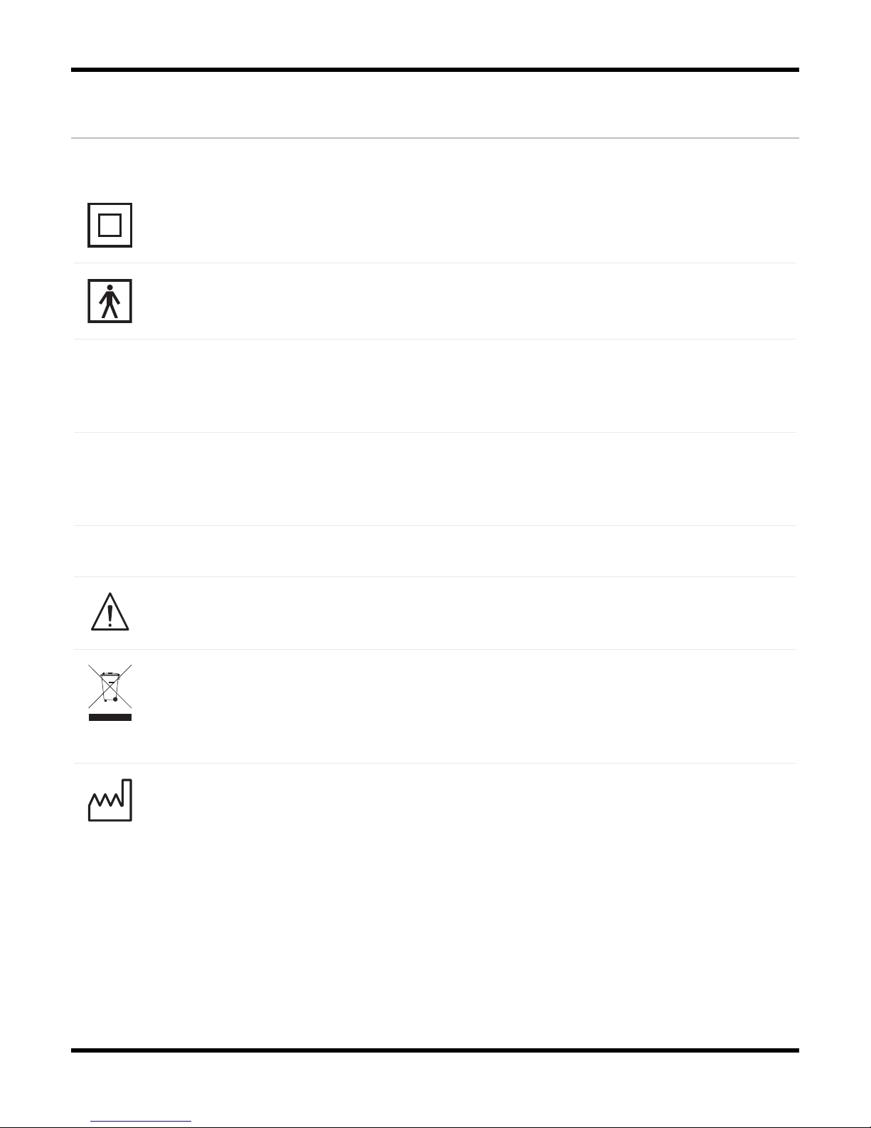
The Embla S4500 is classified as Class II device.
Electric shock: According to the degree of protection against electric shock the
Embla is classified as of type BF.
Ingress of liquids: The Embla S4500 is classified as an ordinary equipment
regarding ingress of liquids, that is, it is not drip-proof, splash-proof or
watertight.
Degree of Safety: The Embla 4500 is not suitable for use in presence of a
FLAMMABLE ANAESTHETIC MIXTURE WITH AIR or WITH OXYGEN or NITROUS
OXIDE.
Mode of operation: Continuous.
Where you see this symbol on any device label, it means "Attention: consult
accompanying documentation".
According to the regulation in Europe on Waste of Electrical and Electronic
Equipment (WEEE) the WEEE may not be disposed of as unsorted municipal waste.
The Embla S4500 should be returned to Embla when it is ready to be disposed of.
Contact Embla at [email protected] for more information.
Where you see this symbol on the device, it means that the date of manufacture is
indicated adjacent to this symbol.
Page 14
7
System Components
The Embla S4500 system is composed of two subunits that are connected together: the
Communication Unit and the Bedside Unit (also known as the Physiological Unit). The enclosure
of the Bedside Unit is connected to a bracket that holds the unit in place. The systems are
connected to a remote standard commercial personal computer through Ethernet/LAN. The
recording data is stored on the personal computer where viewing, reviewing and analysis of
the data can be done in the application software used.
Communication Unit
About the Communication Unit
The Communication Unit supplies the power to the Bedside Unit and communicates between the
Embla S4500 and an acquisition computer over a Local Area Network (LAN). It has additional
inputs for external devices such as a CPAP, and functions in part as a patient isolation unit,
preventing a direct electrical connection between the patient and the external devices
connected to the system.
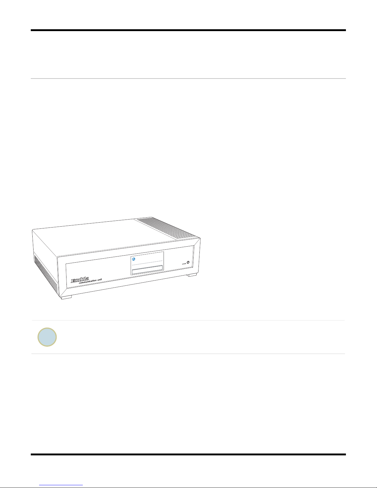
Communication Unit (front view)
Four plastic fasteners are supplied with the system that can be used to secure the
Communication Unit to a wall. See Mounting the Communication Unit for more information.
The unit front panel features a power indicator light (labeled "
") which is green when the
unit is turned on.
Page 15
Embla S4500 Clinical Manual
8
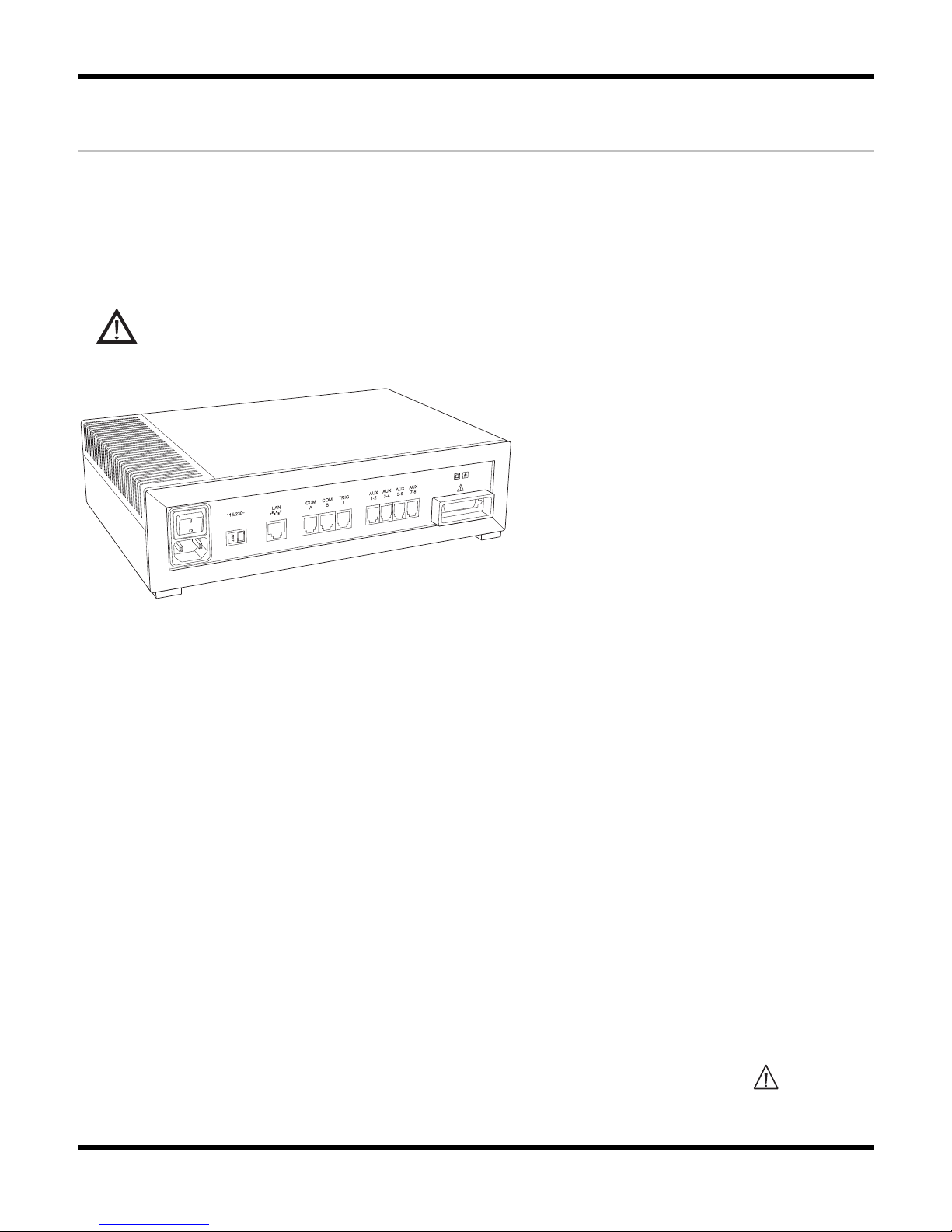
Rear Panel
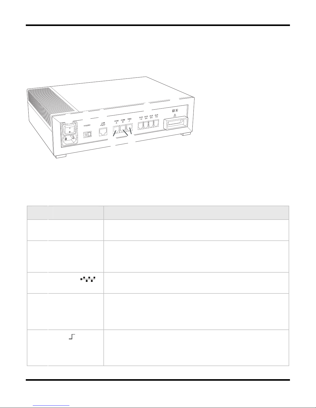
The following figure shows the location of the rear panel components on the Embla S4500
Communication Unit:
B
C
D
G
H
E
F
Communication Unit (rear view)
Table 1 lists and describes the Communication Unit rear panel components and symbols.
Table 1: Communication Unit Rear Panel Components and Symbols
Item Description
1
Mains power
supply
Includes an on/off switch and a mains power input.
2
Voltage
selector switch
(115/230V~)
Determines the voltage used.
3
LAN Port Communication port to the LAN. The required network
connection is twisted-pair (TP) Ethernet.
4
COM A & COM B Serial ports intended for use with supported devices with
digital outputs, such as a CPAP or CO2 devices. Contact Embla
at [email protected] for information on which external
devices can be connected to these ports.
5
TRIG Trigger input/output port. Intended for use with photic
stimulators or other devices requiring a trigger interface. The
Trigger input/output is only supported by the Embla N7000
system.
Page 16
System Components
9
6
AUX 1-8 There are four dual channel auxiliary inputs on the rear panel.
These inputs can each read 2 channels (8 total) and support
devices that output analog signals.
7
Unit Interface
This connection communicates with and supplies power to the
other units in the system.
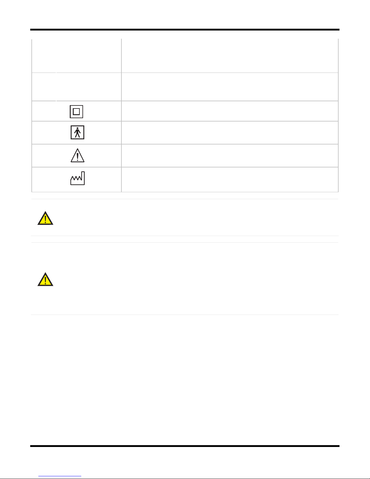
Class II power supply. Double isolation.
Type BF applied part.
Attention: consult accompanying documents.
Where you see this symbol on the device, it means that the
date of manufacture is indicated adjacent to this symbol.
Warning:
The Communication Unit is delivered with the appropriate default voltage setting.
Ensure the voltage selector switch is correctly set before turning the unit on.
Warning:
The use of auxiliary devices compatibility-tested by Embla is recommended. Contact
Embla technical support ([email protected]) for information on which external
devices can be connected to the Communication Unit inputs. When installing an
auxiliary device ensure the tracing from the auxiliary input represents the same
value observed on the display of the auxiliary device. Consult the auxiliary device
clinical manual for applicable calibration routines.
Page 17

Embla S4500 Clinical Manual
10
Communication Unit Cables
Table 2 lists and describes cables used with the communication unit.
Caution:
Always inspect the equipment, particularly the cables and connectors, for evidence
of wear before each study. If evidence of wear is found, remove the worn
equipment from use and contact Embla Technical Support for replacement or
servicing.
Table 2: Communication Unit Cables
Cable Description
Power Cable Plugs into the mains power input on the rear panel of the
Communication Unit and to a standard wall outlet.
Standard
Ethernet Cable
Plugs into the Local Area Network (LAN) port on the rear panel of the
Communication Unit and to an Ethernet wall outlet. The cable is gray
and 5m (197in) long. It is used to connect the system to an already
installed network.
Crossover
Ethernet Cable
Plugs into the LAN port on the rear panel of the Communication Unit
and directly to an acquisition computer. The cable is black with red
connectors on each end and 2.5m (98in) long. The crossover cable is
used, for example, when testing the system and it cannot be used to
connect to an Ethernet wall outlet.
Serial
Communication
Unit Cable
Connects COM A or COM B ports on the Communication Unit to an RS232 serial port on a PC (not required for normal operation) or a
device with an RS-232 port, e.g., an AutoSet device. This cable may
be used for possible troubleshooting purposes.
Bedside Unit
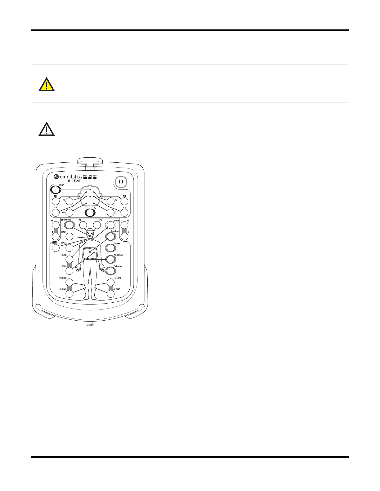
The bedside unit features a color-coded input panel displaying the patient layout, a built-in
impedance button with indicator lights, a one-step disconnect, and 2-pin sensor inputs to reduce
patient hookup time and ensure polarity.
The Bedside Unit reads and transmits physiological channels used during a study, such as EEG,
EOG, EKG/ECG, and respiratory signals. The interface connecting the unit to the
Page 18
System Components
11
Communication Unit is on the underside of the Bedside Unit and is connected to the Bedside Unit
bracket.
Warning:
The interface on the underside of the Bedside Unit should not be touched when the
system is connected to the patient.
Caution:
When you see this symbol on the bedside unit, consult the accompanying
documentation for information about the interface.
S4500 Input Panel
Status Lights
There are three status lights at the top of the Input Panel: PWR, OXI, and REC.
• PWR: Indicates the power supply. A green light indicates the unit is receiving power. If
no light is visible, the unit is not receiving power.
• OXI: Indicates the status of the connection to the oximeter. A green light indicates
connection to the oximeter. If no light is visible, the unit is not connected to the oximeter.
Page 19
Embla S4500 Clinical Manual
12
• REC: Indicates the status of the recording. A green light indicates the unit is recording.
If no light is visible, the unit is not recording.
Impedance Test Button
The impedance test button is located in the top right hand corner of the Input Panel. An
impedance test can be performed when the bedside unit is recording or idle (not recording). To
save the results of the impedance test (as part of a recording), press the impedance test button
when a recording is in progress. For more information, see Testing the Electrode Impedance.
Although it is possible to test impedance using the test button on the input panel, it is
recommended that you use your Embla PSG software to test impedance. If you require
a specific impedance threshold, for example, 5kOhms (to meet AASM guidelines) you
must perform impedance testing using your Embla PSG software.
Channel Inputs
The Bedside Unit reads and transmits a total of 21 channels and includes an input for a ground
electrode (PGND) and a reference electrode. On the Embla S4500, the Reference input label
refers is CZ.
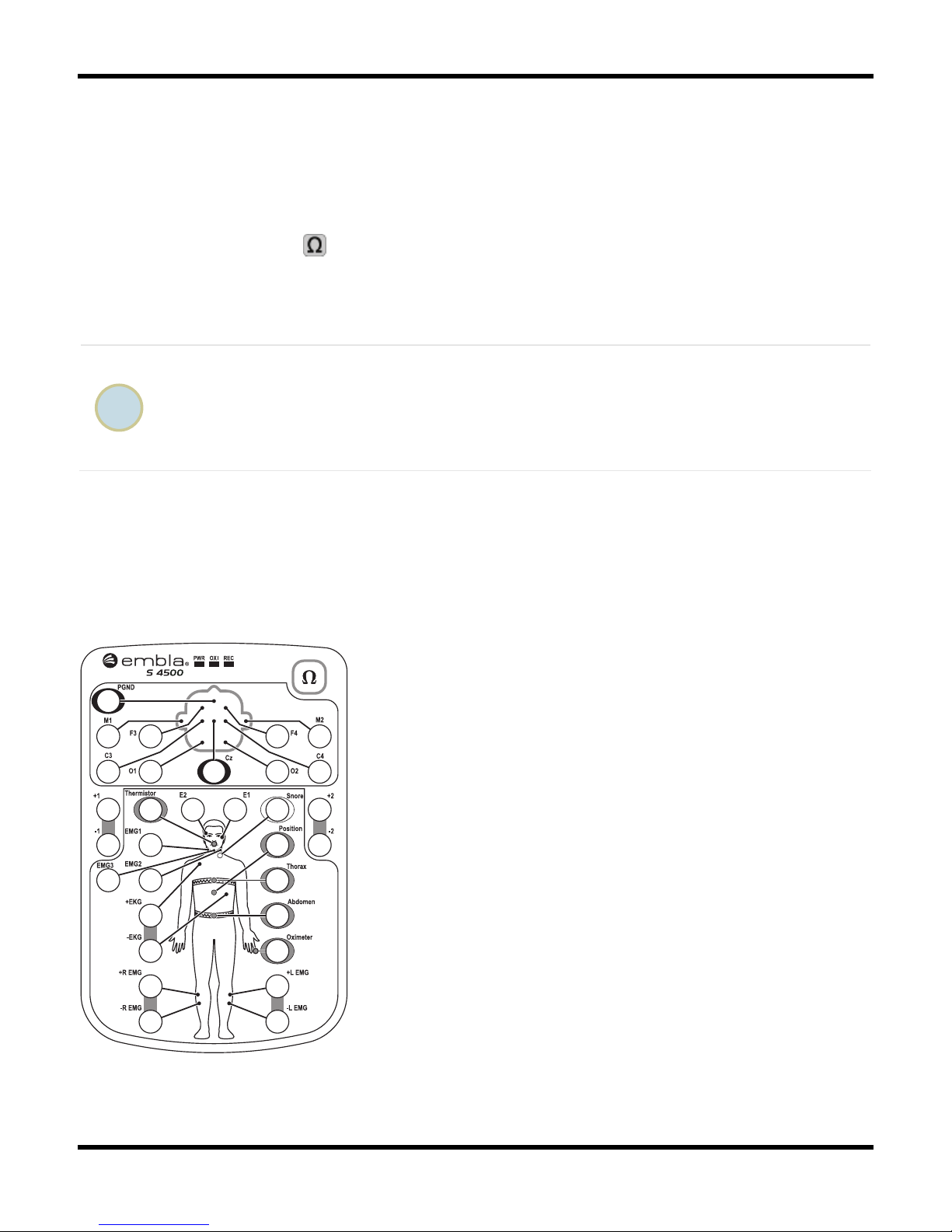
Bedside Unit
Page 20

System Components
13
Referential Channels
The beside unit has 13 referential channels:
• 8 channels (M1, M2, F3, F4, C3, C4, O1, O2) intended for EEG and labeled according
to the international 10-20 System of electrode placement.
• 2 channels (E1, E2) intended for EOG.
• 3 channels (EMG1, EMG2, EMG3) intended for chin EMG signal.
Bipolar Channels
The bedside unit has 5 bipolar channels (indicated by ± symbol).
• ±EKG: intended for EKG/ECG.
• ±R EMG: intended for right limb EMG.
• ±L EMG: intended for left limb EMG.
• The 2 remaining channels, labeled ±1 and ±2, are extra bipolar channels.
Channel inputs on the Input Panel are intended for 1.5mm touch-proof plugs ONLY.
Sensor Input Channels
The beside unit has 6 sensor input channels: 5 respiratory data channels and 1 sensor input
channel for position. These channels have a proprietary two pin connector with different labels,
each with a unique color.
• Thermistor: intended for nasal flow (Color: gray).
• Snore: intended for snore (Color: white).
• Position: intended for body position (Color: purple).
• Thorax: intended for thoracic respiratory effort with XactTrace (Color: blue).
• Abdomen: intended for abdominal respiratory effort with XactTrace (Color: yellow).
• Oximeter: intended for oximetry data (Color: brown).
Sensor inputs on the Input Panel are intended for 2 pin touch-proof type connectors
ONLY.
Page 21
Embla S4500 Clinical Manual
14
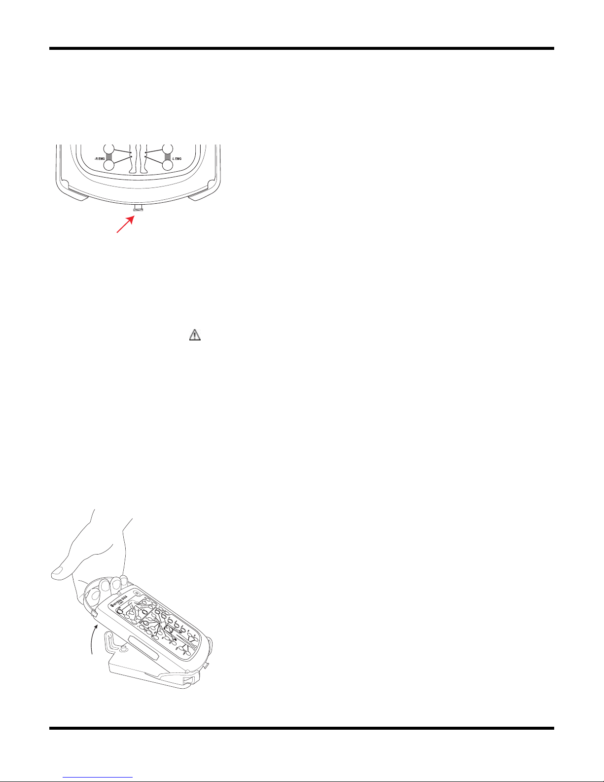
Luer Lock
The bedside unit has 1 Luer Lock Interface. A nasal pressure sensor connects to the Luer Lock
and allows measurement of nasal flow/pressure. A flow generator with pressure tubing can
also be connected to the Luer Lock to record mask pressure.
Luer Lock on Bedside Unit.
Cable
This bedside unit cable connects the Bedside Unit to the Communication Unit. It connects to the
Interface marked with the
symbol, located on the rear panel of the Communication Unit. This
cable is permanently fastened to the mounting bracket and should not be removed unless it
needs to be replaced. When the patient needs to leave the bed, the technician can easily
disconnect the Bedside Unit itself by releasing it from the mounting bracket.
Mounting Bracket
Rugged and mountable anywhere, the Bedside Unit is designed to be easily connected and
disconnected. The mounting bracket included with the system has a quick release feature that
can be mounted on a wall or bedside table. A handle is attached to the Bedside Unit to
simplify mounting and dismounting from the mounting bracket.
Dismounting the Bedside Unit
Page 22
System Components
15
Shoulder Strap
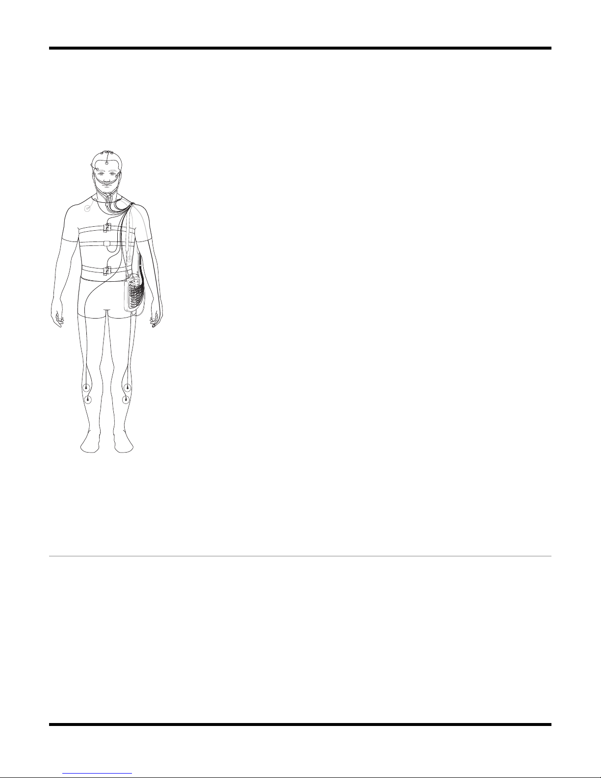
The Bedside Unit is lightweight and can easily be worn by the patient with a strap attachment.
This allows the Bedside Unit to be easily carried when the patient needs to leave the bed. Use
of this accessory, which can be easily fastened to the unit, is optional.
Patient carrying the Bedside Unit with shoulder strap
Sensors
The sensors used with the Embla S4500 system can be ordered online at ShopEmbla
(www.shopembla.com) or from a local Embla distributor.
There are two types of sensors used with the Embla S4500:
Electrodes
The sensors used with the Embla Bedside Unit must have 1.5 mm touch-proof connectors. The
majority of the sensors that are connected to the Bedside Unit are electrodes. The most common
type of electrodes is cup-electrodes (gold, silver, silver-silverchloride). Cup-electrodes require
Page 23

Embla S4500 Clinical Manual
16
conductance paste and that the electrode site be properly prepared and cleaned for lower
impedance values. Cup-electrodes are typically used in recording EEG, EOG, and submental
EMG. Due to the different conduction properties of silver, silver/silver-chloride, and gold, the
same metal type should be used for all unipolar electrodes including the common reference.
Single use electrodes are also frequently used. They are typically used in measuring
EKG/ECG, and EMG from the anterior tibialis muscles. Single use electrodes are usually AgAgCl (silver-silverchloride) electrodes that can be fastened to the skin surface. As with cupelectrodes, the electrode site should be properly cleaned and prepared to achieve low
impedance.
Sensor Inputs
The sensor inputs incorporate sensors for recording respiratory signals and body position
signals.
Only sensors provided by Embla should be used. The Bedside Unit records signals from six
external sensors and one built-in sensor. The external sensors that can be used are abdominal
and thoracic respiratory effort, oral/nasal airflow (thermistor), snoring, oximetry, and position.
The built-in sensor is an airflow pressure transducer. The arrangement of these sensors and
optional sensors will be determined by the type of study being performed.
For a more detailed description of each sensor and their placement on the patient, consult the
Performing a Study chapter.
Table 3: Bedside Unit Internal Sensors
Type Name Description
Internal Pressure
Sensor
The Bedside Unit has a built-in pressure sensor. The pressure is
measured via a nasal cannula connected to the Luer Lock on the
bottom of the unit. The pressure sensor can be used for
measuring both nasal flow and mask pressure.
External
Respiratory
Effort
Sensors
The Bedside Unit accommodates two respiratory effort sensors:
one around the thoracic region and the other around the
abdominal region. The XactTrace – RIP respiratory effort
sensors are used with the Bedside Unit.
External Oximeter
The oximeter is external and measures continuously the degree
of oxygen saturation of the circulating blood.
External
Snoring
An external piezo-electric snoring sensor can optionally be used
with the system. When the snoring sensor is attached to a
Page 24

System Components
17
Type Name Description
Sensor patient's throat, it generates a signal in response to vibration
during snoring. Snoring can also be detected in the pressure
signal from the nasal cannula.
External
Body
Position
Sensor
Used to collect data regarding patient sleep position changes.
External Thermistor
Used to measure airflow. When used with a nasal cannula,
assists in distinguishing apneas from hypopneas. Can also be
used with a CPAP mask to detect mouth breathing.
The use of oral/nasal cannula is NOT recommended.
Page 25
18
Assembling the System
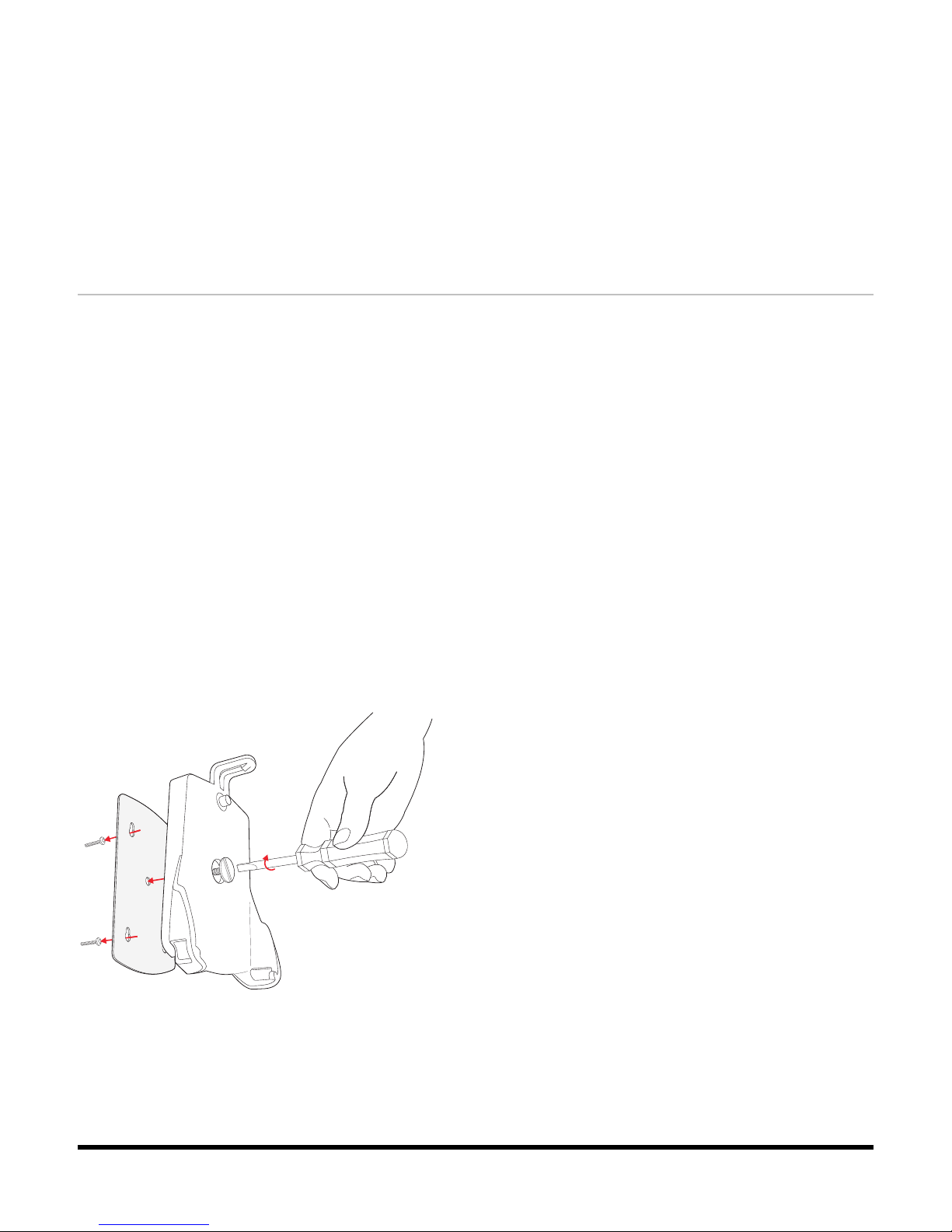
Mounting the Bedside Unit Bracket
The Bedside Unit sits in a bracket that should be mounted before any studies are performed.
The bracket can, for example, be mounted on a wall or a bedside table next to the patient's
bed. The cable from the Communication Unit is already locked into the mounting bracket. No
setup is required.
To mount the bedside unit bracket:
1. Unscrew the bracket from the metal plate.
2. Fasten screws into the four key-shaped holes on the metal plate.
3. Slide the metal plate down so that the screws are held securely in the narrow end of
the key-shaped holes.
4. Tighten the screws.
5. Place the bracket on the metal plate and secure it to the plate with the large screw.
The Bedside Unit can now be easily docked and undocked from the bracket.
Mounting the Bedside Unit bracket
Page 26
Assembling the System
19
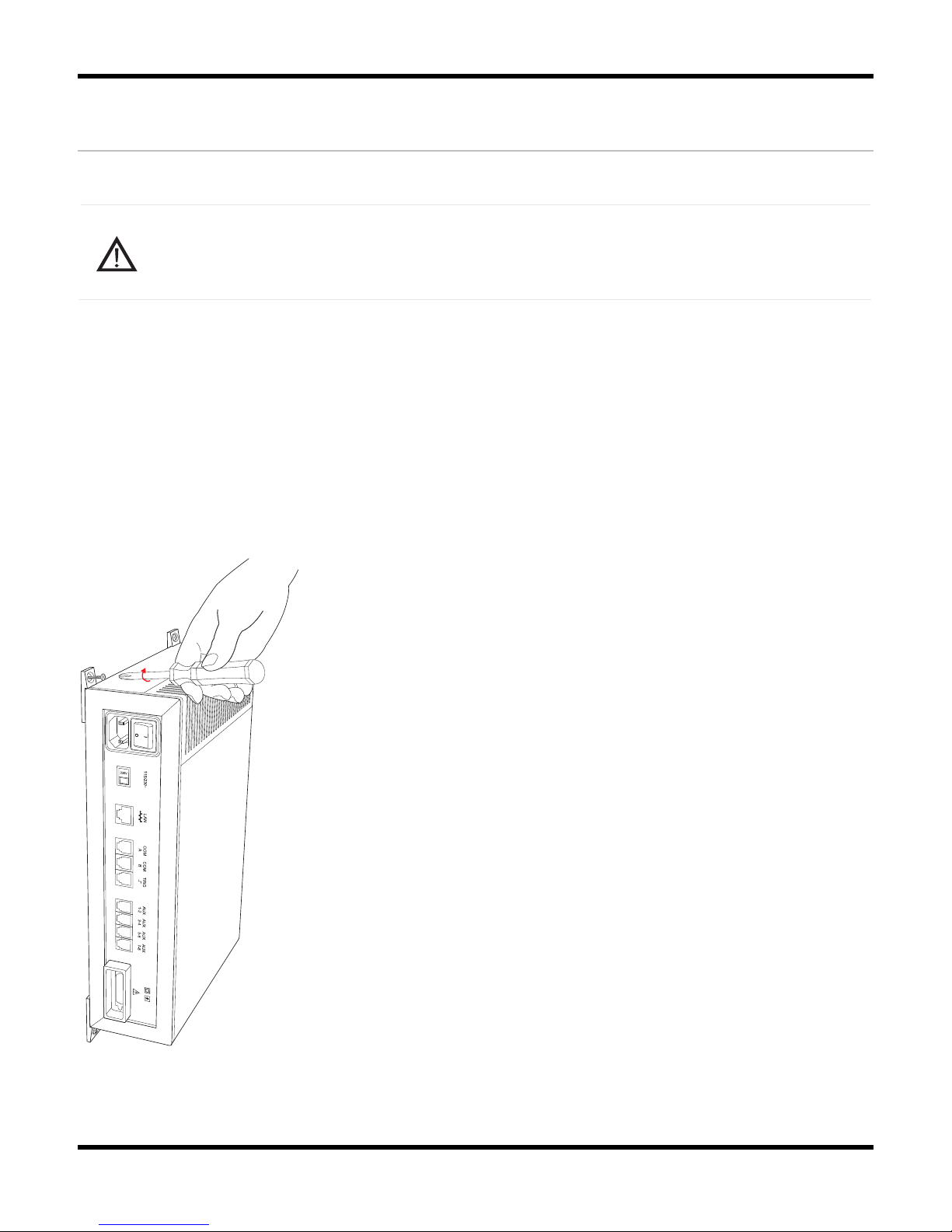
Mounting the Communication Unit
The Communication Unit should be mounted in a well-ventilated area to prevent overheating.
Caution:
Avoid installing the Communication Unit where there is danger of spilling or
exposure to any kind of liquid.
To mount the Communication Unit:
1. Unscrew the gray rubber feet from the underside of the Communication Unit.
2. Replace the feet with the fasteners: slide the ridge of the fastener into the groove on
the unit's underside so that the holes of the fasteners are aligned with the
corresponding holes on the Communication Unit.
3. Attach the fasteners with two screws each.
4. Screw the Communication Unit to the wall.
Mounting the Communication Unit
Page 27
Embla S4500 Clinical Manual
20
Creating and Attaching an ID Card to the
Communication Unit
More than one Embla S4500 can be used to record on the same acquisition computer. Each
device is identified in the acquisition application by its serial number and given a custom name.
Clearly identify the physical devices in accordance with their identification in the application.
Creating an ID card for the unit will ensure that each communication unit serial number and
custom name are easily accessible.
To prepare and attach an ID card:
1. Create an ID card that includes both the custom name and the serial number (found on
the bottom of the Communications Unit.
2. Place the card inside a plastic sleeve or other protective cover.
3. Attach the card to the Communication Unit where it is clearly visible and away from
any ventilation opening.
FXXXXXX-CU-XXXX
Embla 1
bla
®
Typical ID card location
Do not place the ID card on the ventilation opening.
Page 28
Assembling the System
21
Connecting the Units
Connecting the Communication Unit
The Communication Unit should be placed in a well-ventilated area to prevent overheating.
Caution:
Avoid installing the Communication Unit where there is danger of spilling or
exposure to any kind of liquid.
Communication Unit rear panel
To connect the communication unit:
1. Confirm that the voltage selector switch is set correctly.
2. Confirm that the Communication Unit is turned off.
3. Connect the gray Ethernet cable to the port labeled LAN on the Communication Unit
rear panel.
4. Connect the cable to the Ethernet outlet on the wall. It is recommended that the net
being used for the sleep study be isolated from other net users.
5. Connect any external devices that will be used with the system. Devices that have a
digital output should be connected to the COM connections. Devices that have analog
output signals should be connected to the connectors labeled AUX. Check the
input/output ranges before connecting external devices. Please contact
[email protected] for information on which devices are recommended and supported
by Embla. See Technical Specifications for more detailed information on the AUX and
COM inputs.
6. Connect the Bedside Unit cable to the interface labeled with this symbol:
.
Page 29
Embla S4500 Clinical Manual
22
7. Connect the power cable to the input located beneath the On/Off button, and then
connect it to a wall outlet.
Connecting the Bedside Unit
The cable from the Communication Unit is already locked into the mounting bracket and does
not require setup.
Connecting to the Bracket
The lightweight bedside unit and mounting bracket provide mobility and stability. The bedside
unit connects to a base bracket via a quick release mechanism.
Caution:
Do not touch the interface on the rear panel of the Bedside Unit when the system is
connected to the patient.
To connect the bedside unit to the bracket:
1. Confirm that the mounting bracket has been properly secured.
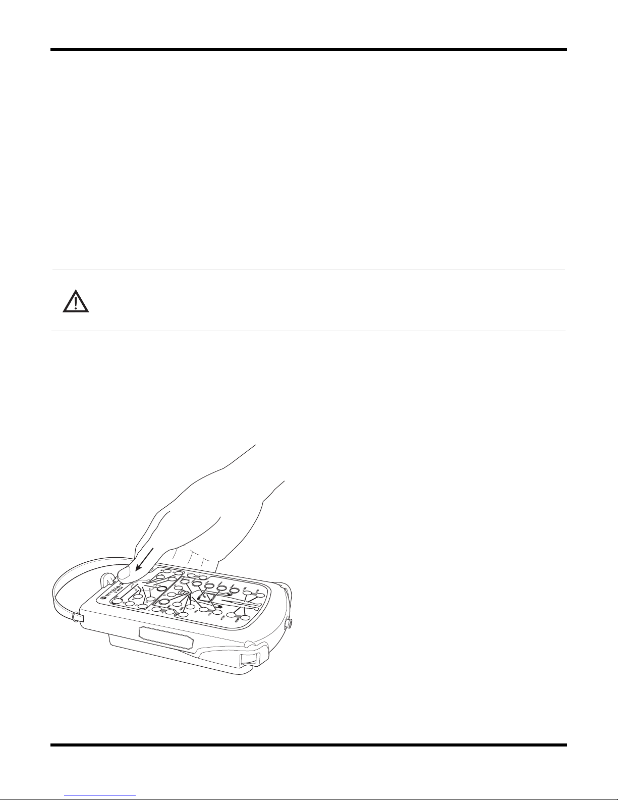
2. Hold the Bedside Unit by the handle and rest its bottom end into the bracket.
3. Press the top end of the Bedside Unit down into the bracket until it clicks into place.
Securing the Bedside Unit in the bracket
Page 30
Assembling the System
23
Disconnecting from the Bracket
The bedside unit is easily disconnected from the base bracket via the quick-release mechanism.
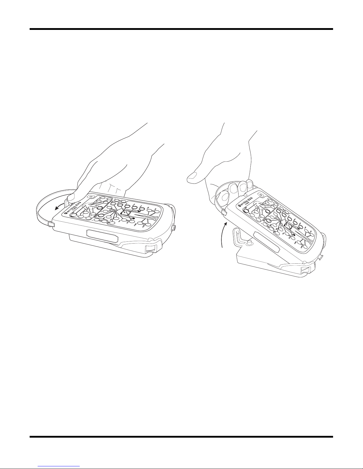
To disconnect the bedside unit from the bracket:
1. Push the quick-release clip away from the unit.
2. Hold the handle and pull the Bedside Unit out of the bracket.
Releasing the quick-release clip Lifting the Bedside Unit from the bracket
Page 31

Embla S4500 Clinical Manual
24
Caution: Connections
Only a trained operator should connect and disconnect the Embla system.
The operator must check the input and output ranges before connecting third party
devices to the system.
The system units may fall if they are not secured according to the instructions in this
manual.
Do not pull on the system cables.
Do not connect units that have been exposed to liquid.
Do not use damaged cables and connectors.
Always inspect the equipment, particularly the cables and connectors, for evidence
of wear before each study. If evidence of wear is found, remove the worn
equipment from use and contact Embla Technical Support ([email protected]) for
replacement or servicing.
Installing the System on the Network
Installing the Embla S4500 on a network should only be done by a trained technician. For more
detailed instructions, consult the following articles available on the Embla knowledge base
Web site, or contact Embla Technical Support ([email protected]):
• Connecting the Embla S4500
Source: http://www.embla.com/support/knowbase/show.asp?ID=293
• Troubleshooting Network Connections with the Embla S4500
Source: http://www.embla.com/support/knowbase/show.asp?ID=292
If you do not have Internet access, you can find these articles on your software installation CD.
The Embla system connects to the acquisition computer through an Ethernet network. An industry
standard twisted-pair cable with RJ45 connectors is used to establish the connection.
The acquisition computer and the system need to be connected to the same Ethernet network. A
standard Ethernet adapter is used for that purpose. Many new computers have Ethernet
adapters integrated on the motherboard. In other cases a standard 10/100 Ethernet adapter
can be added to the computer.
The Embla communicates with the computer using the TCP/IP protocol. On all Windows 2000
and XP installations, the TCP/IP protocol is enabled by default when Windows detects an
Ethernet adapter.
Page 32
Assembling the System
25
Firewall software can block network traffic between the computer and the
Communication Unit. To ensure proper operation, disable any firewall software that
may be running on your computer.
Connection Types
The Ethernet connection between the Embla system and the acquisition computer can be
established in different ways. The most common configurations are detailed here. The
conventional way to set up a network is to use a star topology with one central hub or switch. A
switch, rather than a hub, is strongly recommended. Adequate 10/100 switches are widely
available and cost effective.
Isolated Network
It is recommended to set up a small isolated network containing one or more Embla systems
and one or more acquisition computers. By isolating the network it will not be affected by
downtime or other limitations of the pre-existing network and vice versa.
The network can be installed by placing the network switch in the control room and connecting
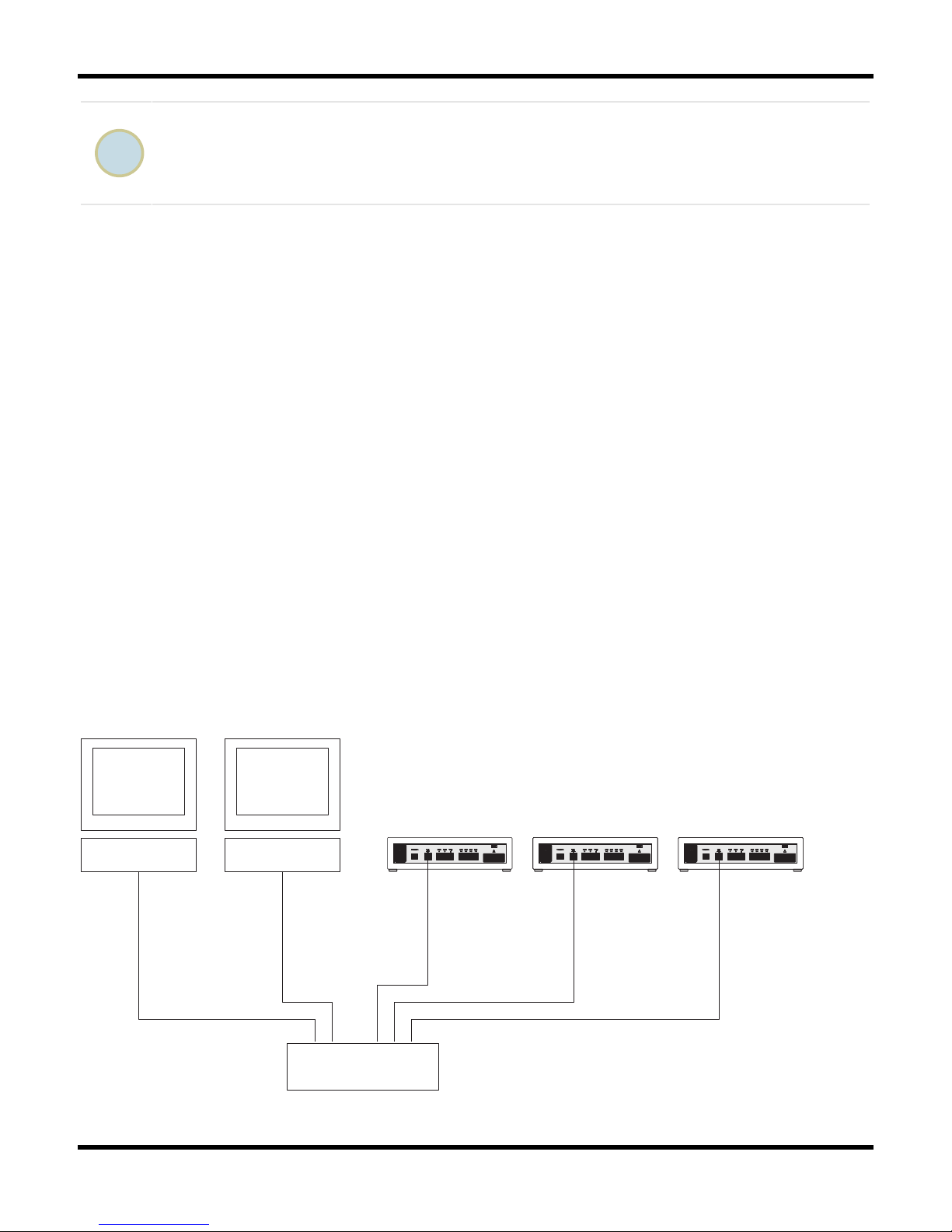
all the devices, both Emblas and computers, to the switch with standard Category 5 twistedpair Ethernet cables. Most switches have a small green LED close to each port, which lights up if
a device is connected to that port. After connecting all the devices and turning them on, make
sure that the corresponding LED lights up on the switch. In case the acquisition computer needs
to be connected to a larger hospital network, a second Ethernet adapter may be added to the
computer.
Computer Computer
10/100 Switch
Communication Unit
Communication Unit
Communication Unit
Ethernet Cable
Ethernet Cable
Ethernet Cable
Ethernet Cable
Ethernet Cable
Schematic diagram of a typical Embla S4500 network
Page 33

Embla S4500 Clinical Manual
26
Part of a Larger Network
It is possible to connect the Embla systems and the acquisition computers directly to a larger
Local Area Network (LAN). This is typically carried out by the IT department of the hospital or
organization running the network. To make the system a part of a larger network, each system
should be connected to a central switch which is usually located in a central wiring cabinet out
of reach. Coordination with the people responsible for running the network is critical.
Page 34

27
Performing a Study
Study Types
The Embla system is designed to be flexible and can be used in different ways. Depending on
the kind of study you desire, different sensors, and additional interfaces will be used. Table 4
describes the standard and physiological study setups for performing a sleep study with the
Embla system.
Table 4: Study Type Setups
Study Type Sensors
Standard EEG, EOG, EKG/ ECG, and EMG electrodes and leads. (2) XactTrace
– RIP Respiratory Effort Sensor, nasal cannula, Oximeter Flex Sensor,
Body Position Sensor (optional), Thermistor (optional), Snoring Sensor
(optional).
Physiological EEG, EOG, EKG/ECG, and EMG electrodes and leads.
Attaching the Electrodes
Clinicians should use their own standard practices to attach electrodes to patients undergoing a
sleep study. The instructions below refer to a study using the 10-20 system. Although the S4500
Bedside Unit only features electrode inputs commonly used in a PSG study, the same standards
apply when attaching the electrodes. The instructions are meant only as a helpful reference
and follow recommended sleep study guidelines.
Place the electrodes according to the desired study type.
Caution:
Always inspect the equipment, particularly the cables and connectors, for evidence
of wear before each study. If evidence of wear is found, remove the worn
equipment from use and contact Embla Technical Support ([email protected]) for
replacement or servicing.
Page 35
Embla S4500 Clinical Manual
28
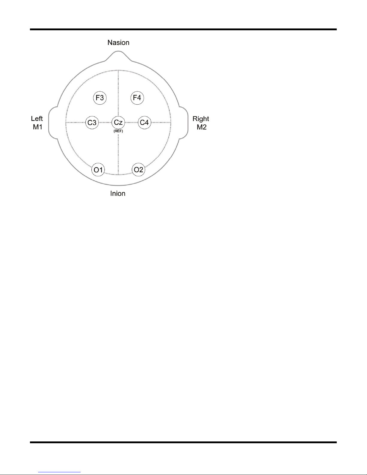
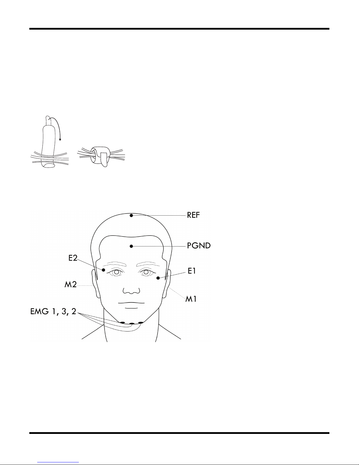
Electrode placement in a standard Embla S4500 PSG study
To attach the electrodes:
1. First prepare the sites for the electrodes: The skin should be cleaned with an approved
skin erosion cream to obtain an electrode –skin resistance less than 10kΩ.
2. Measure the distance from the nasion to inion along the mid-line through the vertex.
3. Make a preliminary mark at the midpoint (Cz). In Embla S4500 recordings, a common
reference (REF) electrode is placed here. The CZ input on the Embla S4500 can only
be used as a REF placement. It is not intended to be an EEG input.
4. Center this point in the transverse plane by marking the halfway point between the left
and right preauricular points. The intersection of marks from steps 1 and 2 give the
precise location of Cz.
5. Reposition the measuring tape at the mid-line through Cz and mark the points 10% up
from the inion (Oz) and nasion (Fpz).
6. Reposition the measuring tape in the transverse plane through Cz and mark 10% (T3)
and 30% (C3) up from the left preauricular point and 10% (T4) and 30% (C4) up
from the right preauricular point.
7. Position the tape around the head through Fpz, T3, Oz, and T4. Ten percent of this
circumference distance is the distance between Fp1 and Fp2 and between 01 and 02.
Mark these four locations on either side of the mid-line.
Page 36
Performing a Study
29
8. The second marks for O1 and O2 are made by continuing the horizontal mark for Oz.
Do this by holding the tape at T3 and T4 through Oz, and extend the horizontal mark
to intersect the previous O1 and O2 marks.
9. To establish the final marks for C3 place the tape from O1 to Fp1 and make a mark
at the midpoint of this line. When extended, this mark will intersect the previous C3
mark. Repeat on the right side for C4.
10. Secure the electrode leads in Cable Wraps above the patient's head:
12
Securing the cable wraps
A standard polysomnographic recording uses the electrode locations displayed in the following
figure:
Example of electrode locations for a standard PSG recording. Not shown is this figure are electrode
placements F3, F4, C3, C4, O1 and O2e.
Page 37
Embla S4500 Clinical Manual
30
Conditions for use of electrodes
The conductive part of electrodes and their connectors, including the ground
electrode, should not contact other conductive parts including earth.
To prevent the hazard of burns, all electrodes should be removed from the patient
before using high frequency (HF) surgical equipment.
The interconnection of several equipments can cause a summation of leakage
currents that may be dangerous to the patient.
To protect the patient against the effect of discharge, all electrodes should be
removed from the patient before using a cardiac defibrillator.
There are no means of indicating an inoperative electrocardiograph.
Avoid accidental contact between the connected but unapplied applied parts and
other conductive parts including those connected to protective earth.
Attaching the Oximeter and Oximeter Flex Sensor
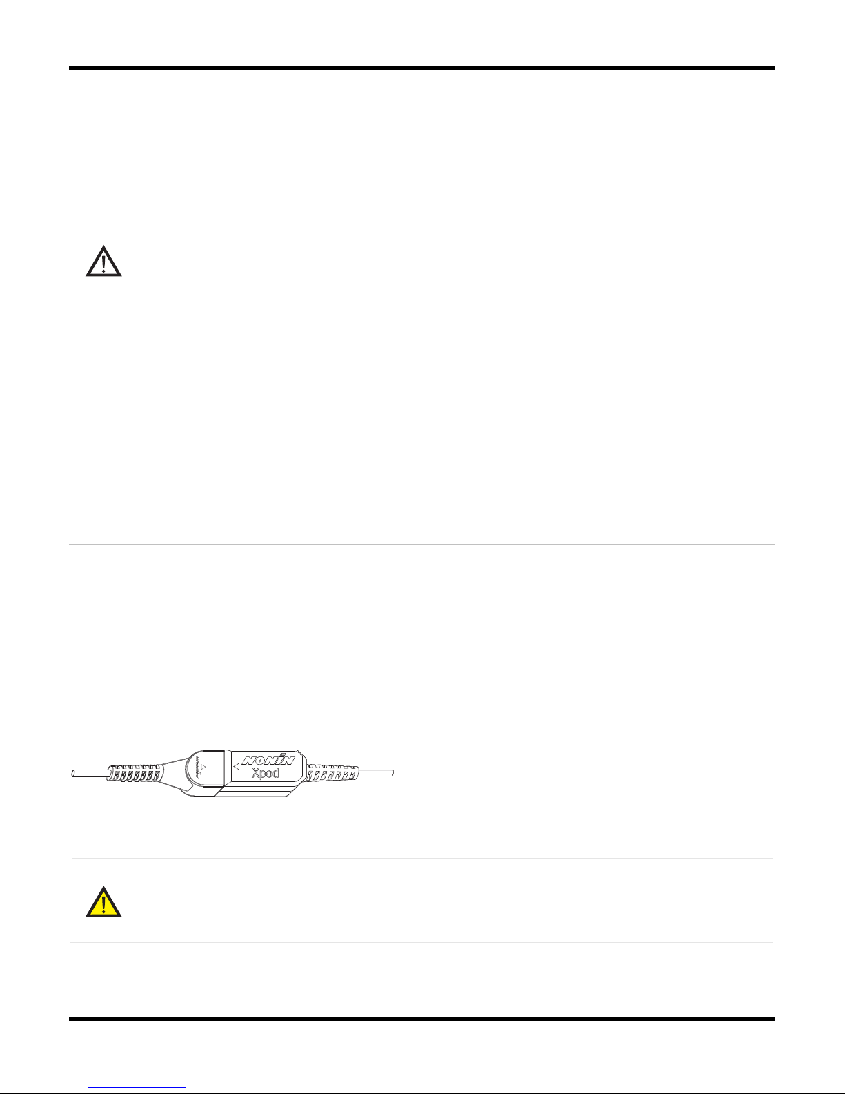
The Nonin oximeter is external and can accommodate a wide range of pulse oximeter sensors
from which it receives information. The oximeter, by shining light through the finger, detects the
amount of light that travels through, thereby providing an indirect measure of the oxygen
saturation.
The oximeter is calibrated to closely approximate functional oxygen saturation values. Recalibration is not required as the oximeter performs all computations from the internal software
and there are no critical parts to drift.
Nonin Xpod Oximeter
Warning:
The pulse oximeter alone should not be used for continuous monitoring as no low
alarm SpO2 is provided.
Page 38

Performing a Study
31
The Oximeter Sensor
The Bedside Unit and the oximeter transform the information received from the Oximeter
Sensor into four signals: oxygen saturation, pulse, pulse plethysmograph waveform, and Beatto-beat SpO2.
Table 5: Signals Received from the Oximeter Sensor
Signal Description
Oxygen
Saturation
The arterial hemoglobin oxygen saturation is displayed in units of
percentage SpO2 over a fixed number of heartbeats.
Pulse The pulse detected indicates the heart rate of the patient.
Pulse
Plethysmograph
Waveform
The pulse waveform measured by the oximeter is an indicator for
peripheral blood flow. It may be used to indicate heart rate. It is
possible to use pulse waveform as a visual aid in the manual scoring of
brady- and tachycardias. Furthermore, the pulse waveform is an
indicator of the signal quality of the oximeter sensor. A clear pulse
waveform signal tells the clinician that the oximeter signal is reliable.
Note that the plethysmograph waveform displayed is not proportional to
the pulse volume.
Beat-to-beat
SpO2
The beat-to-beat SpO2 shows the saturation level on a given heart
beat, without averaging, and is therefore, faster and more receptive
than the averaged SpO2. This signal is sensitive to movement artifacts.
The manufacturer of the oximeter, Nonin Medical Inc., has validated
the oximeter. For more information, see Technical Specifications, or
consult the Embla web site (www.embla.com).
Attaching the Oximeter Flex Sensor
The Oximeter Flex Sensor records oxygen saturation and pulse. The preferred application site
for the oximeter flex sensor on adults is the index finger. However, other fingers may be used
where the finger thickness is between 5mm and 21mm (0.2" and 0.8"): dimension "H" in the
following figure.
Page 39
Embla S4500 Clinical Manual
32
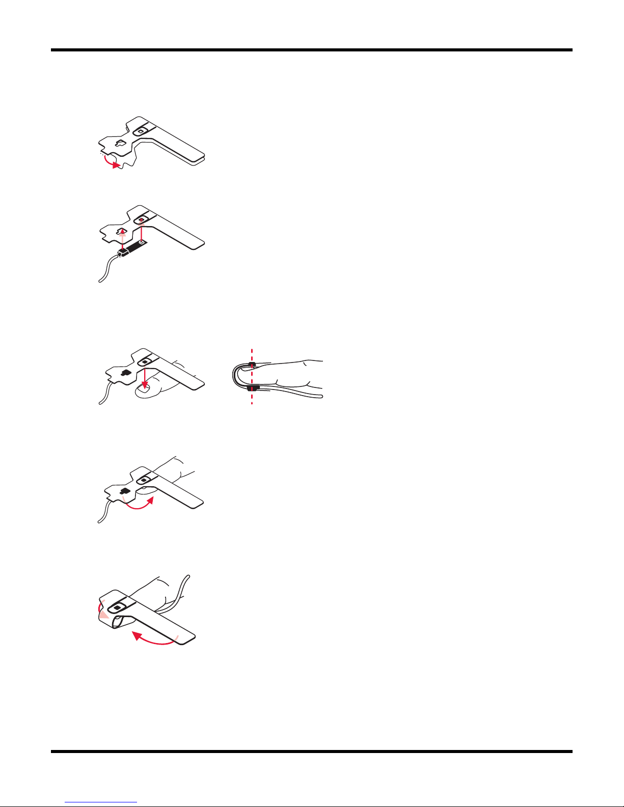
To apply the oximeter:
1. Grasp the blue tab on the FlexiWrap™. Peel the paper backing away.
2. Firmly press the sensor against the adhesive side of the FlexiWrap.
3. Carefully position the adhesive side of the FlexiWrap on the finger as shown in the
figure below. Make sure that the dotted line is at the tip of the finger. (This positioning
helps line up the light emitter and the light detector).
4. Carefully fold the flap of the FlexiWrap over the fingertip. Make sure that the light
emitter and the light detector are vertically aligned.
5. Wrap the side flaps of the FlexiWrap around the sides of the finger as indicated by
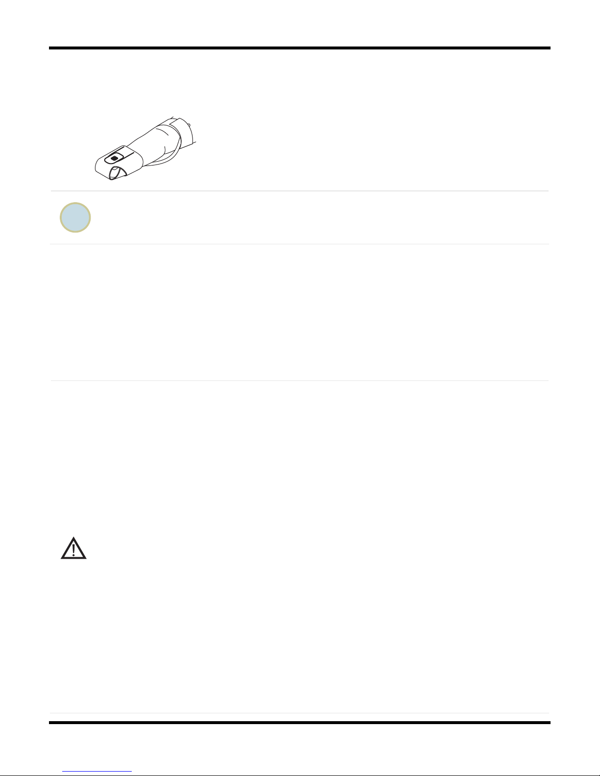
the arrows in the figure.
Page 40
Performing a Study
33
6. For best results secure the sensor wire with medical tape, preferably around the base
of the finger. Make sure that the tape securing the wire does not restrict the blood
flow.
Dispose of the FlexiWrap after each application.
Other Oximeter Sensors
It is possible to use other Nonin standard oximeter sensors certified to carry the CE mark with
the Bedside Unit such as: pediatric sensor, disposable sensor and finger-clip sensor. These have
to be ordered separately. The various sensors are either intended for short term continuous
monitoring or extended duration. The operator should consult the documents that come with the
sensors for information on the correct usage.
Caution: Conditions for use of an oximeter
An oximeter alone should not be used to reach important clinical conclusions. Clinical
caution must always be exercised, and other means should be used for confirmation
whenever possible.
Misuse or improper handling of the sensors can result in damage of the sensor or the
cable. This may cause inaccurate measurements and readings.
Remove fingernail polish or artificial fingernails before applying the sensors.
Fingernail polish or artificial fingernails may cause inaccurate readings.
Do not autoclave, ethylene oxide sterilize or immerse the sensors in liquid. Unplug
the sensors from the Bedside Unit before cleaning or disinfecting.
Operation of oximeter sensors can be affected by the presence of strong ambient
light. Shield the sensor area (with a medical tape, for example) if necessary.
Inspect the sensor application site at least every 6 to 8 hours to ensure correct
sensor alignment and skin integrity. Patients may react differently to the sensors
depending on their medical status and skin condition. Do not use adhesive material
if the patient exhibits an allergic reaction to it.
The oximeter may be unable to detect lower saturation values with the same
degree of accuracy and precision as higher saturation values. It may also be unable
Page 41
Embla S4500 Clinical Manual
34
to quantify the degree of hyperoxemia present.
Interferences such as movement, abnormal hemoglobins, intravascular dyes, low
perfusion states and skin pigmentation may influence the function of the pulse
oximeter.
Note that the temperature of the SpO2 probe may reach up to 42°C.
Attaching XactTrace™ Respiratory Effort Sensors
The Bedside Unit accommodates two respiratory effort sensors: one around the thoracic region
and the other around the abdominal region. The XactTrace sensor uses a Respiratory Inductive
Plethysmograph (RIP) and is much more sensitive and reliable than typical respiratory effort
sensors, especially in cases of paradoxical breathing. The XactTrace sensor generates a high
quality signal that is a measure of the chest/abdomen circumference. These sensors help to
distinguish between obstructive, central or mixed apnea and give an indirect measure of the
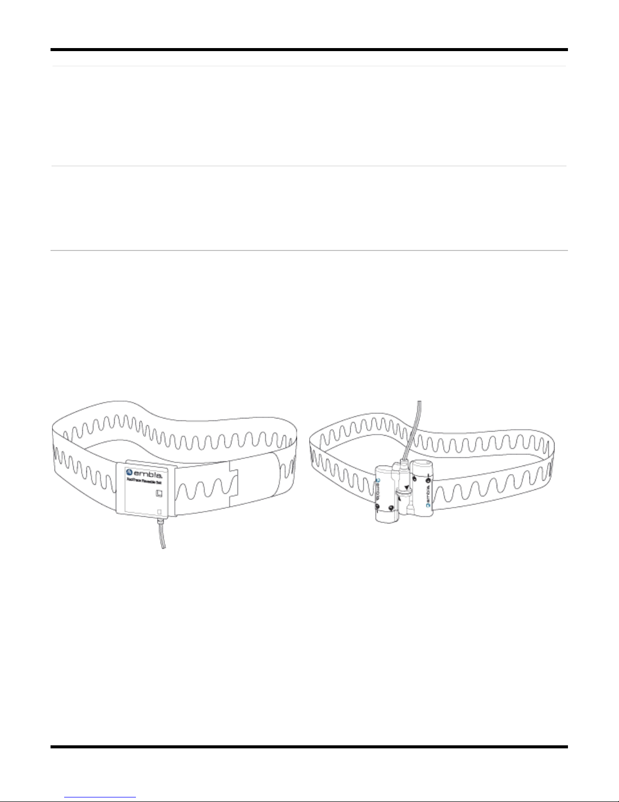
respiratory tidal volume. The XactTrace belts are available in single-use and reusable types.
XactTrace Reusable Belt XactTrace Single Use Belt
Fitting the Single-Use XactTrace Belts
The XactTrace belts must be custom fit for each patient. When using the XactTrace belts, it is
advised to avoid all unnecessary contact with moisture.
Page 42
Performing a Study
35
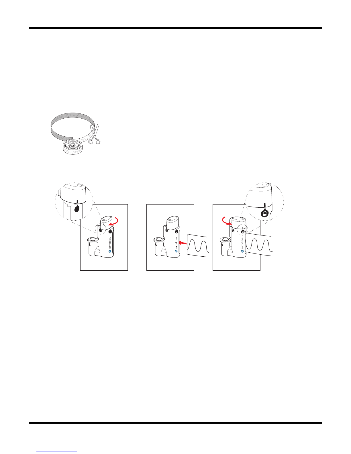
To prepare the single use belt for the study:
1. Encircle the belt around the patient's chest to approximate the circumference for the
thoracic belt.
2. When cutting the belt, reduce its circumference by 10-15cm (4-6") so that it will stretch
around the thorax. The belt should fit snugly to prevent slippage during the night. It is
important to use sharp scissors for a clean cut. The wire should not exceed the end of
the belt.
3. Secure the cut ends of the belt into the Belt Lock with the blue connector according to
the following steps:
i. Turn the top end of the Belt Lock clockwise to open the catch. The white mark
on the top should match the open lock symbol on the catch.
ii. Insert the cut end of the belt into the catch. Make sure to insert the end all the
way to the bottom of the catch.
iii. Twist the top end of the Belt Lock counter clockwise to close the catch. When
the white mark on the top matches the closed lock symbol on the catch, the Belt
Lock is properly closed.
4. Prepare the abdominal belt in the same manner, only this time fitting the belt around
the patient's stomach at the navel and using the Belt Lock with the yellow connector.
Page 43
Embla S4500 Clinical Manual
36
Attaching the XactTrace Single-Use Belts to the Patient
XactTrace belts are attached to the patient and are used to measure respiratory effort. The
XactTrace sensor generates a high quality signal that is a measure of the thoracic (chest) and
abdominal circumference. This signal provides a qualitative measure of ventilation and flow.
The XactTrace belts are intended to be worn over the patient's nightclothes.
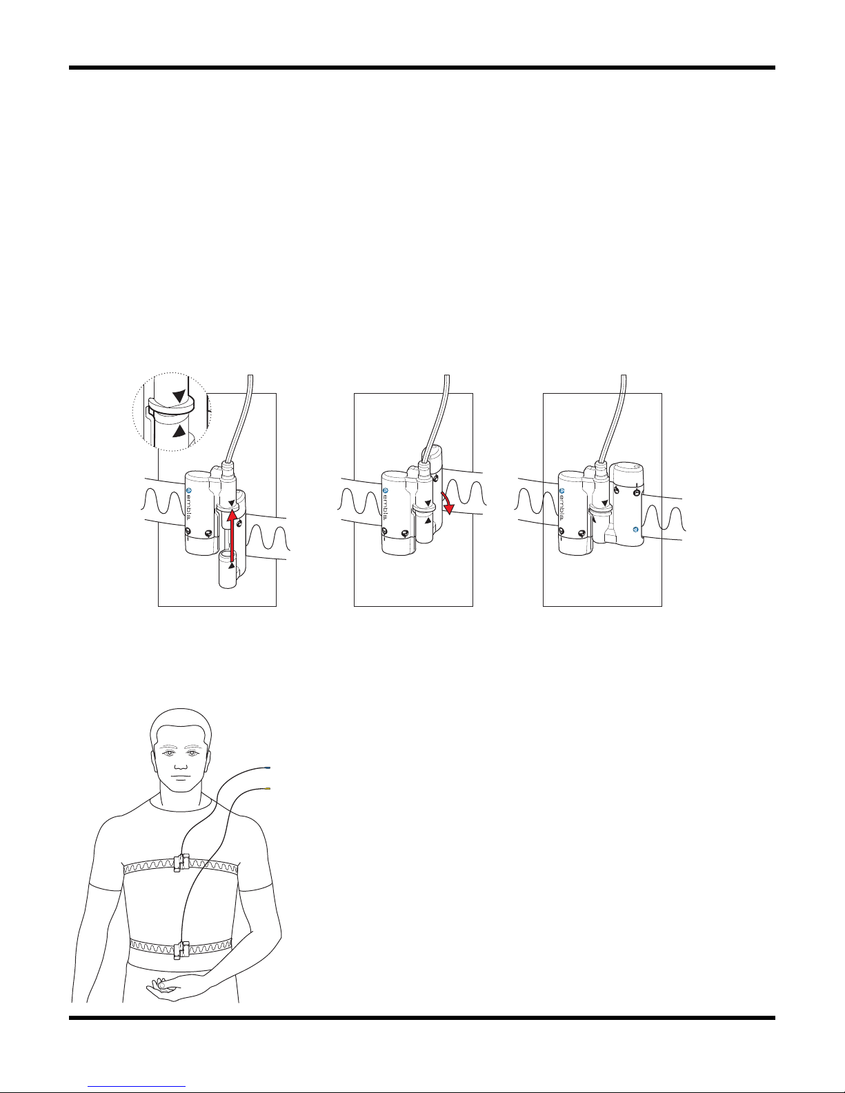
To attach the belts to the patient:
1. Place the abdominal belt with the yellow sensor plug around the patient's stomach at
the navel.
2. Take the two components of the black Belt Lock and connect them as shown below:
embla
®
3. Place the thoracic belt with the blue connector around the patient’s chest under both
arms.
4. Connect the second belt lock.
Page 44
Performing a Study
37
Thoracic and abdominal XactTrace belts attached to the patient.
Storing the Belt Lock
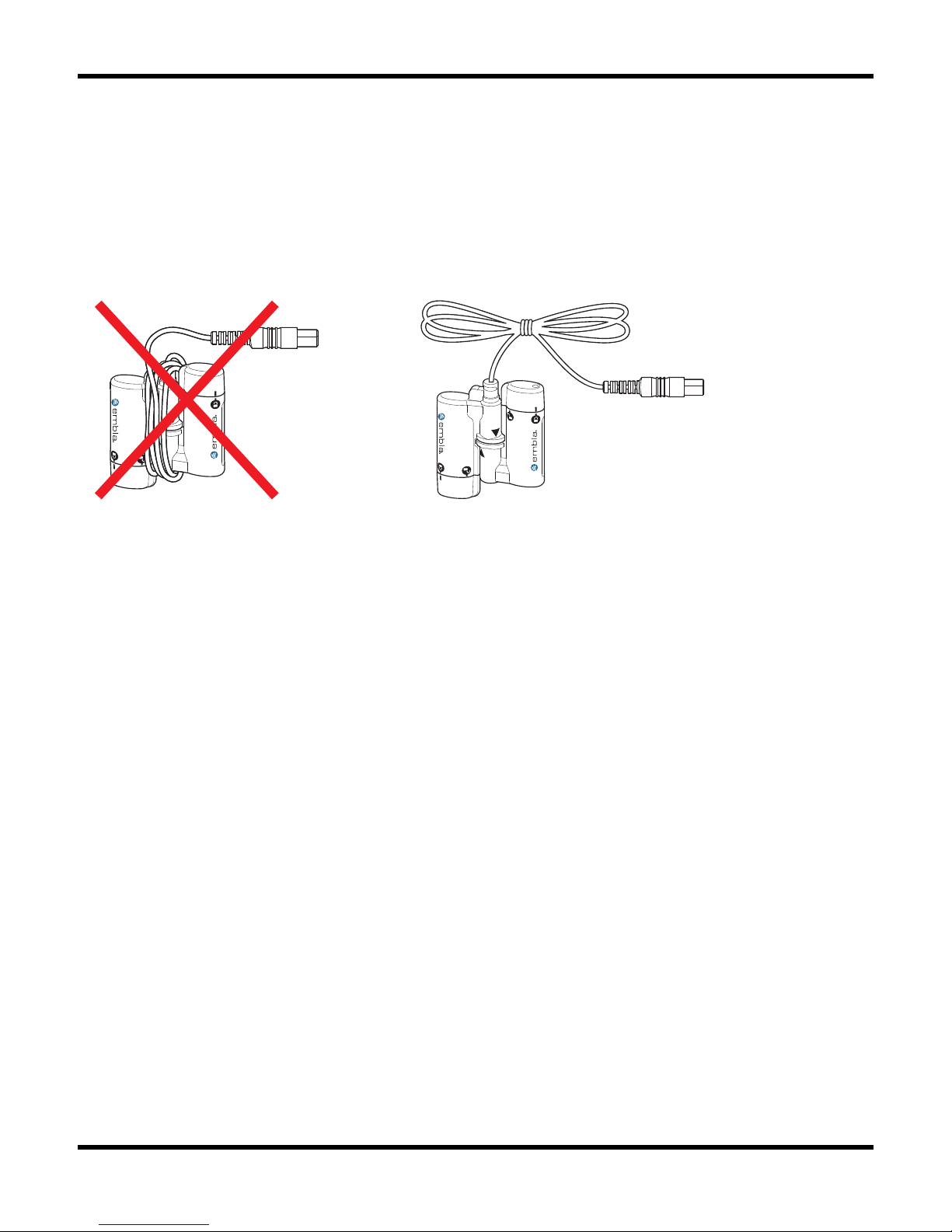
Proper storage of the XactTrace belt locks between recordings will increase their lifetime. To
protect the sensor cable from damage, do not wrap it tightly around the Belt Lock as it may
cause the cable to break where it connects to the Lock.
Incorrect Correct
Considerations for Use
• Avoid all unnecessary contact with moisture.
• The belts are intended to be worn over nightclothes.
• Do not stretch the belts too tightly around the patient as this may cause discomfort. To
prevent the belt from slipping during the night, the position can be fixed with medical
tape.
• Care must be taken not to cut any cables when cutting the belts.
• If the top end of the lock is not properly secured, the signal will be affected.
• The belt is intended for single use only.
Fitting the XactTrace Reusable Belts
The XactTrace reusable sensor belts come in three sizes that should fit all adult patients. The
length of each belt can be adjusted to ensure a good fit using the Velcro patches provided
(see below for details). The belts should fit the patient snugly without being uncomfortably
tight. Measure the patient’s circumference and use the following table as a guide to choose the
appropriate belt size.
Page 45
Embla S4500 Clinical Manual
38
Full Size Reduced Size
Cm inches cm inches
Large 141-194 56-76 120-167 47-66
Medium 104-142 41-56 83-114 33-45
Small 78-104 31-41 57-77 22-30
Attaching the XactTrace Reusable Belts:
When using the XactTrace belts, it is advised to avoid all unnecessary contact with moisture.
The belts are intended to be worn over nightclothes.
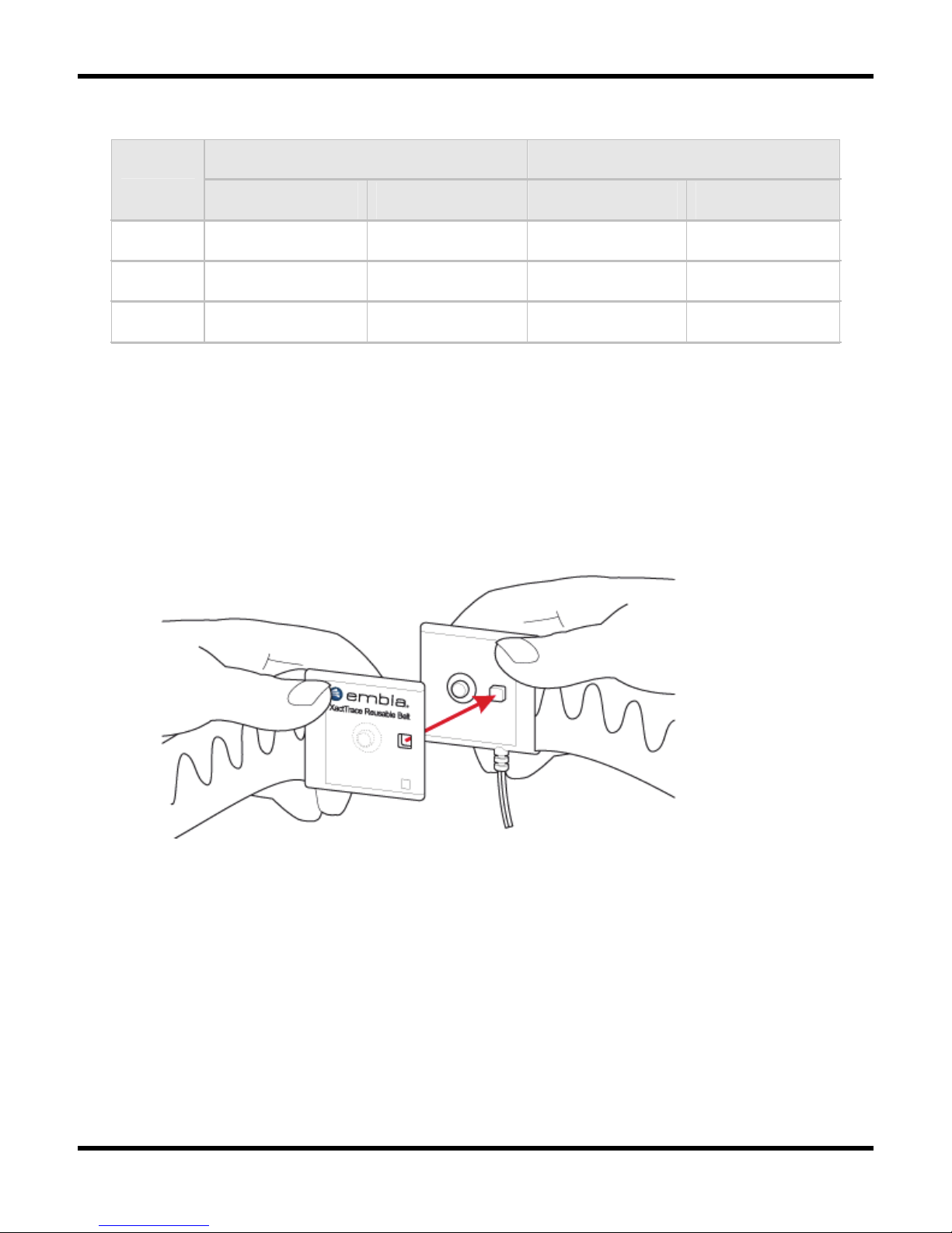
1. Place the belt with the yellow connector around the patient’s abdomen at the navel.
2. Snap the two components of the snap lock together as shown below:
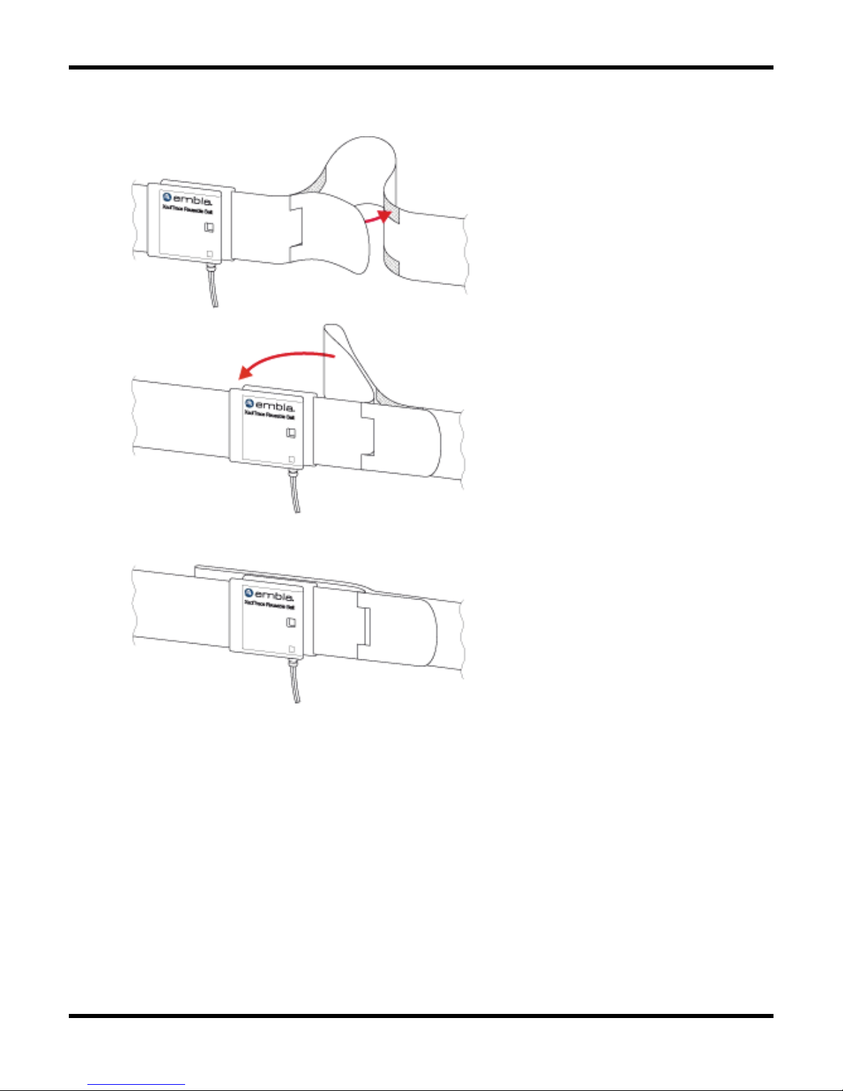
3. If the belt is too loose, use the Velcro patches to reduce the circumference according to
the following steps:
Page 46
Performing a Study
39
4. Place the belt with the blue connector around the patient’s chest under the arm and
snap the snap lock together.
5. Insert the blue and yellow sensor plugs into the appropriate color-coded inputs.
Storing the Reusable Belt
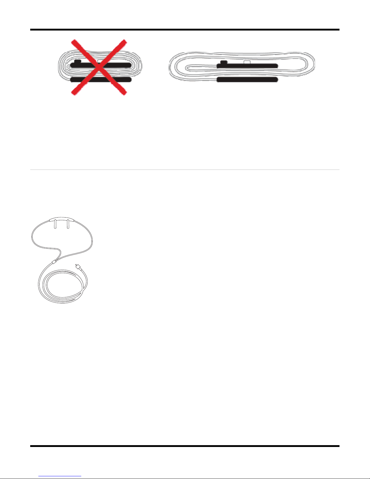
Proper storage of the XactTrace belts will increase the lifetime of the belts. To protect the belt
and the sensor cable from damage, keep the following in mind when storing the belts between
studies:
• Do not wrap the belt tightly around the belt lock because it will cause strain on the
wire where it connects to the lock. Rather fold it loosely together.
Page 47
Embla S4500 Clinical Manual
40
• Do not wrap the sensor cable tightly around the belt lock as it may cause the cable to
break where it connects to the lock.
Attaching the Nasal Pressure Sensor
The Bedside Unit has a built-in pressure sensor. The pressure is measured via a nasal cannula
connected to the Luer Lock on top of the Bedside Unit. The pressure sensor can be used for
measuring both nasal flow and mask pressure. With the appropriate software support the
signal from the nasal cannula can be used to detect snoring.
Nasal pressure sensor
Page 48
Performing a Study
41
To apply the nasal cannula:
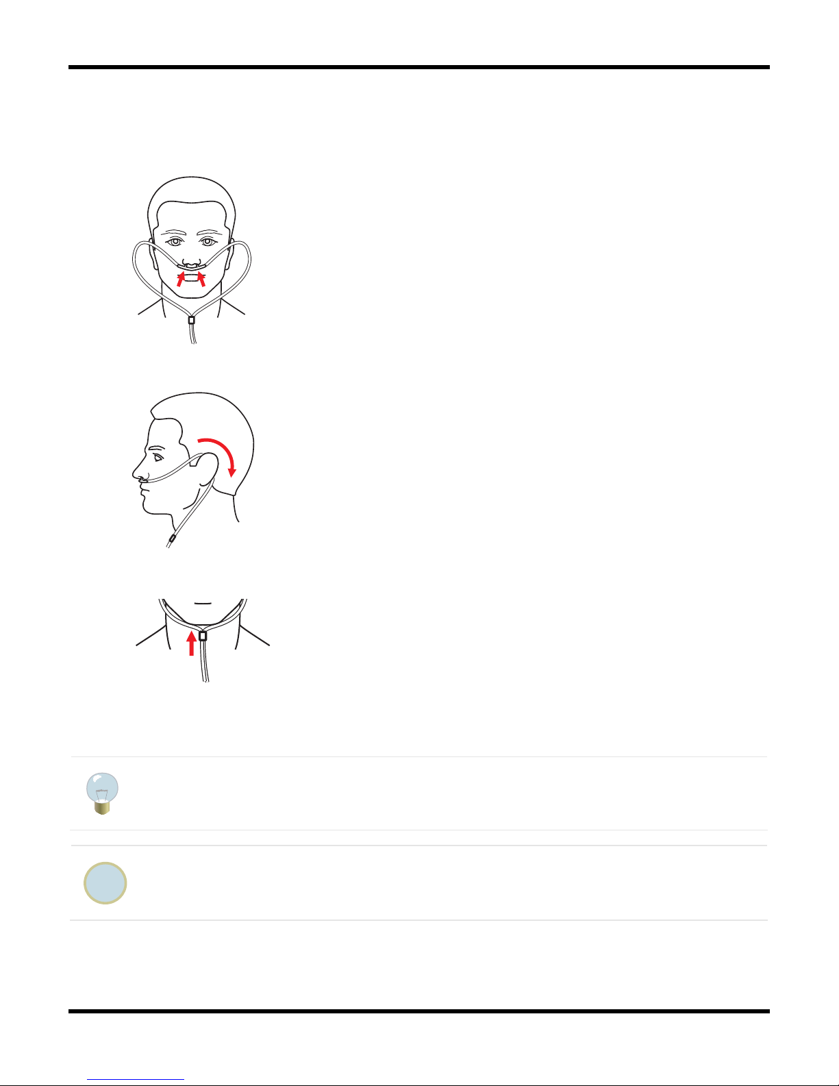
1. Place the nasal prongs in the nostrils. The prongs should bend downwards in the nostrils
to effectively measure nasal breathing.
2. Loop the air cannula tube over the ears and then position it under the chin.
3. Tighten the loop by pushing the toggle towards the chin.
4. Secure the nasal cannula to the Luer Lock on the Bedside Unit and twist clockwise to
tighten.
Medical tape can be used to fasten the cannula tube to the patient's cheeks.
The use of oral/nasal cannula is NOT recommended. Dispose of the nasal cannula
after each use.
Page 49
Embla S4500 Clinical Manual
42
Attaching the Snoring Sensor
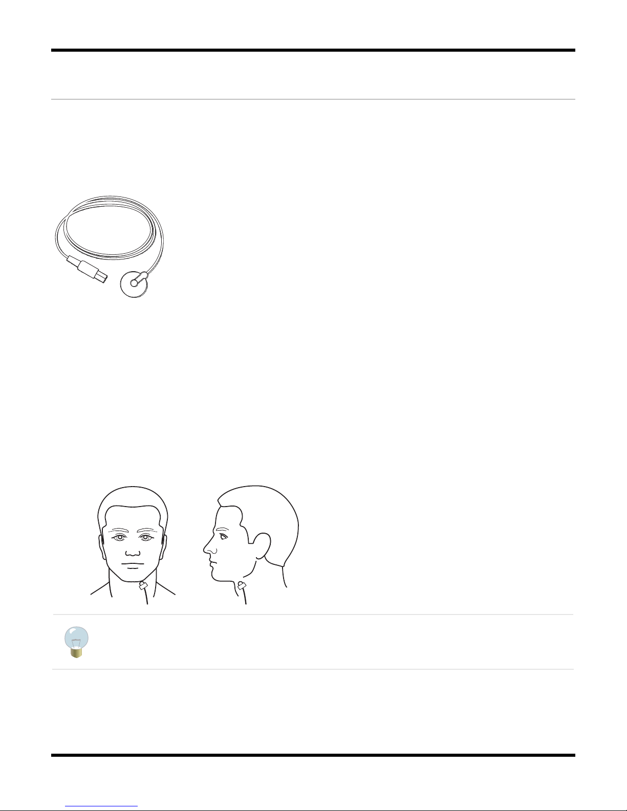
An external piezo-electric snoring sensor can optionally be used with the system. When the
snoring sensor is attached to a patient's throat, it generates a signal in response to vibration
during snoring. Relying on vibrations rather than actual sounds eliminates all artifacts
associated with external noises. The snoring signal is converted to an analog voltage that can
be measured.
Snoring sensor
To attach the snoring sensor:
1. Have the patient simulate a snore while the clinician gently places his fingers on his or
her neck to find the best position for the sensor. The spot that exhibits the most
vibration should be selected. The snoring sensor should not be placed directly on the
larynx.
2. Place the side of the sensor with the raised bump next to the skin.
3. Fasten with medical tape.
A second piece of medical tape can be placed about 15cm (6in) away from the
sensor in order to relieve tension on the sensor wire.
Page 50

Performing a Study
43
Attaching the Thermistor
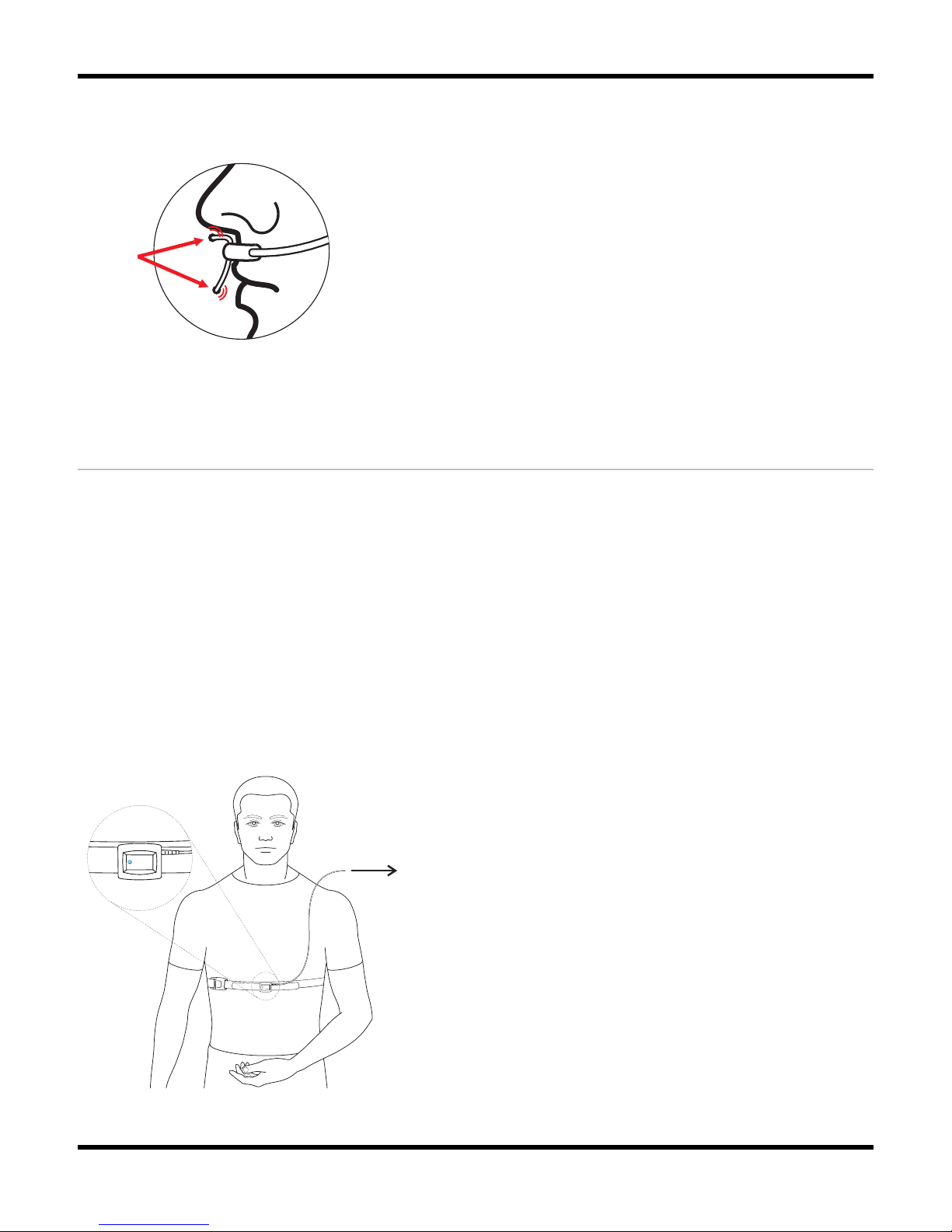
Airflow may be measured with a thermistor that connects to the Bedside Unit. When the
thermistor is used alongside a nasal cannula it can help distinguish between apneas and mouth
breathing. The quality of the recorded signal depends on variables such as filters, placement,
patient's respiration, room temperature and CPAP pressure.
The thermistor should be attached after the nasal cannula has been attached.
To attach the thermistor:
1. Bend the nose sensor forward in a rounded angle, slightly away from the sensor body.
2. Position the thermistor on the upper lip. Position the nasal probes right under the
nostrils so that they are exposed to the maximum available airflow. The probes should
not touch the skin or enter the nose.
3. Loop the sensor wire over the ears (as with the cannula tube), and then position it under
the chin.
3. Tighten the sensor wire loop, if necessary, by pushing the toggle towards the chin.
Page 51
Embla S4500 Clinical Manual
44
4. Secure the sensor wire to the cheeks with a medical tape. The sensor tips should not
touch the skin as skin contact will significantly attenuate the signal amplitude.
Attaching the Body Position Sensor
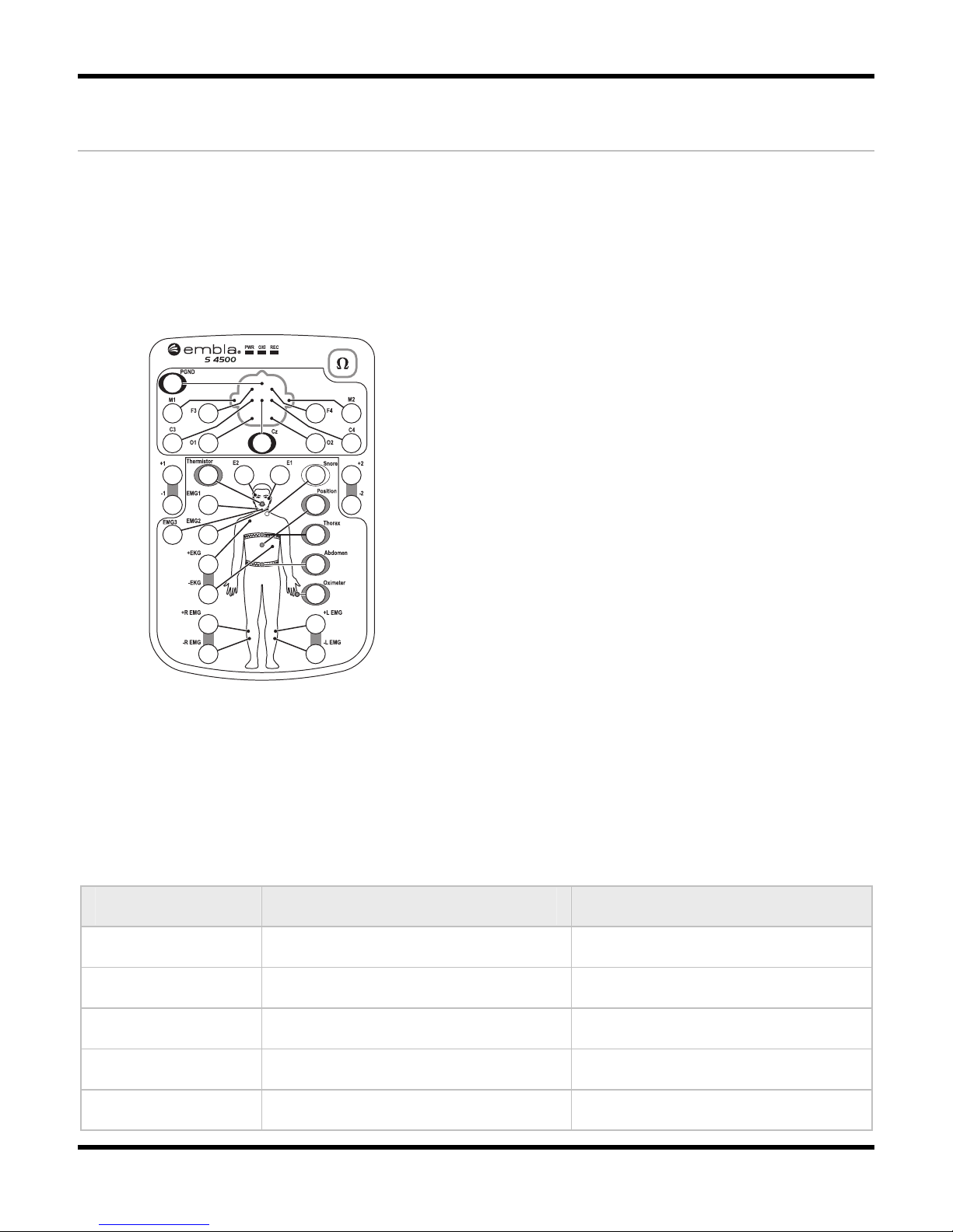
Body position may be measured with a position sensor that connects to the Beside Unit. When
the sensor is attached to a patient, it generates a signal in response to body position changes.
To attach the body position sensor:
1. To achieve correct position output, secure the elastic strap firmly around the centerline
of the chest or abdomen.
2. Attach the sensor to the strap by using the hook Velcro on the sensor's back. To ensure
proper placement, the Embla logo should be turned correctly.
3. Plug the 2 pin touch-proof connector in the Bedside Unit. No external interface or
power supply is necessary.
embla
®
embla
®
Insert the connector in the appropriate input on the Bedside Unit
Page 52
Performing a Study
45
Connecting Sensors to the Bedside Unit
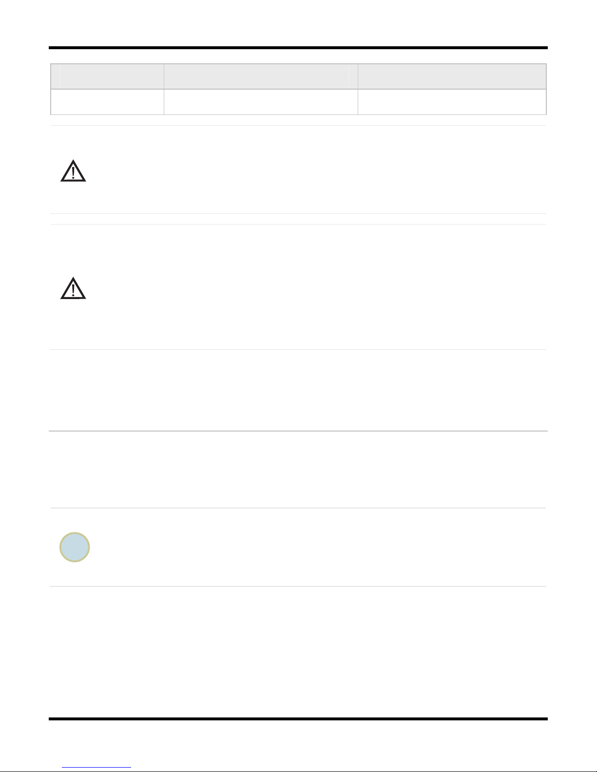
Once the sensors are attached to the patient, you must connect these inputs to the Bedside Unit
Input Panel. The clinician can prepare the patient and the system in whatever order is most
convenient. See Table 6 for sensor color code references and connector types.
To connect the sensor to the Bedside Unit:
1. Connect the electrodes to the appropriate marked channel inputs.
2. Make sure to connect other sensors to the bipolar channels as specified in the
acquisition application.
3. Insert the sensor connectors into the color-coded inputs on the Bedside Unit.
4. Connect the nasal cannula to the Luer Lock. Twist clockwise to tighten.
Table 6: Sensor Input Color Code
Color Sensor Connector Type
Yellow Abdominal Respiratory Effort 2 pin touch-proof
Blue Thoracic Respiratory Effort 2 pin touch-proof
White Snoring 2 pin touch-proof
Gray Thermistor 2 pin touch-proof
Brown Oximeter 3 pin touch-proof
Page 53
Embla S4500 Clinical Manual
46
Color Sensor Connector Type
Purple Position 2 pin touch-proof
Caution:
Before the patient leaves the bed, ensure that all cables have been safely secured
and the patient has no risk of falling. The operator should assist the patient and
check the equipment. Secure the cables and electrode leads in a cable wrap above
the patient's head.
Caution: Conditions for use of sensors
Misuse or improper handling of any sensor can result in damage of the sensor or the
sensor cable. This may cause inaccurate measurements and readings.
Do not use damaged sensors, cables or accessories.
Ensure that cables do not encircle the patient's neck. Special attention is required in
the case of children.
Testing the Electrode Impedance
Electrode impedance testing is built into the system. Electrode impedance may be tested in two
ways: by pushing the impedance test button on the Bedside Unit, and in the software during a
recording. Consult your sleep acquisition Embla PSG software user manual for further
information on how to manipulate the electrode impedance testing in the acquisition software.
Although it is possible to test impedance using the test button on the input panel of the
Bedside Unit, using your Embla PSG software to test impedance is recommended. If
you require a specific impedance threshold, for example, 5kOhms (to meet AASM
guidelines), you must perform impedance testing using your Embla PSG software.
When an impedance test is started, the system sends a very small current for a fixed period of
time to the appropriate channels on the bedside Unit. No signals are received from the
electrodes during that time.
During an impedance test, the REF channel is used as a reference, and the actual values of
impedance are displayed in the Embla PSG software. The impedance of the electrode
connected to the REF channel will not be tested. However, if any of the other channel inputs
Page 54

Performing a Study
47
being tested have acceptable impedance, the electrode connected to the reference channel
should also have acceptable impedance.
• Performing an Impedance Test When Not Recording
If an impedance test is performed when not recording, the impedance is tested on all
unipolar and bipolar inputs of the Bedside Unit. The test is started by pushing the
impedance test button
on the Bedside Unit. When an impedance test is started, all
the electrode inputs on the Bedside Unit flash orange. The lights then turn green,
indicating that they are working. After that, the impedance test scans start. Electrodes
that have impedances higher than 10kOhm light up in orange while electrode inputs
that have impedance lower than 10kOhm light up in green. When the impedance test
is complete, the electrodes with too high impedance will continue to display an orange
light while electrodes with acceptable impedance display since no recording is taking
place.
• Performing an Impedance Test During a Recording
If an impedance test is started during a recording, the test is performed on the
channels selected in the Embla PSG software, and is started from within the software
application. Consult your PSG software user manual for details on how to start and
stop the impedance test in the software. The results of the impedance test are stored
with the recording.
• Stopping an Impedance Test
An impedance test that has been started can be stopped before it has finished.
To stop the impedance test:
o Push the impedance test button on the Bedside Unit.
For information on how to stop the impedance test in the acquisition software, consult
your PSG software user manual.
If the impedance test results in an error, check the reference electrode (REF)
connection. The impedance test may also result in an error if the impedance of all
electrodes is too high.
Page 55

Embla S4500 Clinical Manual
48
Activating the Calibration Test Signal
The S4500 recorder, together with the Embla PSG software, allows you to verify the gain for
the Bedside Unit. When you activate the calibration test signal from the Embla PSG software,
the system sends a calibration signal for 30 seconds to all channels on the Bedside Unit. The
signal has an amplitude of +/- 50µV and a frequency of 0.1Hz. See your Embla PSG
software manual for calibration instructions.
During Use
If the patient needs to leave the bed during a recording, the clinician or technician is
responsible for properly disconnecting the equipment.
The patient should be advised against placing the Bedside Unit on the floor when going to the
bathroom. The unit must be hung on a hook or other similar fastener mounted on the wall close
to the toilet for that purpose. The Bedside Unit should not be placed under a comforter or a
blanket.
Caution:
To prevent the sling from encircling the patient's neck, the Bedside Unit shoulder
strap should not be used when the patient is in bed. Special caution must be taken
with children.
Page 56

49
System Maintenance
Cleaning the System Units
The Embla S4500 bedside unit is covered with plastic coating and does not require cleaning
after each use. When necessary, clean with a damp cloth. Isopropyl alcohol may also be used
for disinfecting the exterior of the unit. The contact of liquid to the inner parts and the
connectors of the units should be avoided at all times. The bedside unit plastic coating does not
withstand cleaning with substances such as acetone.
Cleaning Sensors
The sensors that come in contact with the patient should be cleaned before reuse. Table 7
describes the cleaning procedure associated with each sensor.
Table 7: Sensor Cleaning Instructions
Sensor Instructions
Oximeter Flex Sensor This sensor can be cleaned with Isopropyl alcohol or sterilized
with ethylene oxide (cold cycle).
Oximeter, Thermistor,
and Snoring Sensor
These sensors should be cleaned with Isopropyl alcohol.
XactTrace Belt Lock,
Snoring Sensor, and
Thermistor
These sensors may be safely wiped clean with hospital grade
cleaner that is not corrosive to plastic or metal, and then dried
with a clean, dry cloth.
Care should be taken to avoid cleaning solution coming into
contact with the sensor connectors For sterilization, a standard
procedure for gas sterilization should be implemented. Do not
autoclave.
Page 57

Embla S4500 Clinical Manual
50
Sensor Instructions
Body Position Sensor This sensor may be wiped clean with hospital grade cleaner
that is not corrosive to plastic or metal and then dried with a
clean, dry cloth. Care should be taken to avoid contact of the
cleaning solutions with the connectors. For sterilization, a
standard procedure for gas sterilization should be implemented.
Do not autoclave.
The elastic strap may be machine washed in gentle cycle at
40°C or hand washed in warm (not hot) solution of hospital
grade laundry detergent and then air dried.
To ensure patient safety, the entire assembly must be completely dry before each use.
Single Use Sensors
The following items are disposable and intended for single use only:
• Nasal cannula
• XactTrace Single-Use belts
Environment
The following limitations apply to both storage and shipment of the Embla S4500:
• The Embla should be stored in a clean, dry environment with a temperature range
between -20°C (-4°F) and +60°C (140°F).
• The operating temperature range is between +5°C (41°F) and +45°C (113°F).
• Avoid using the Embla in high humidity, where there is a danger of water condensing
inside the recorder.
• The warranty is void if the system is opened.
• Handle the Embla system with care. Despite its rugged design, the unit is not
waterproof, splash-proof or dirt-proof.
• Keep connectors free of dust and dirt.
Page 58

System Maintenance
51
Factory Calibration
The Embla system is calibrated in production and no further calibration is needed.
Disposal
The units in the Embla system are to be disposed of like other electronic equipment.
The Communication Unit contains Nickel Metal Hydride (NIMH) batteries that should be
disposed of as such.
Page 59

52
Troubleshooting
This section provides some steps that can be taken to quickly troubleshoot the Embla S4500
system. If the system does not operate correctly after troubleshooting, contact your local
representative.
• No part of the system is serviceable by third party technical personnel.
• All service on the system (including fuse replacement) shall be performed by Embla or
authorized parties only.
• In case of a system failure, the system should be sent in for repair or replacement
depending on the warranty agreement.
Problems Starting a Recording
Problems encountered when starting a recording may be caused by the connections.
To correct the problem:
1. Check the voltage setting.
2. Ensure the Communication Unit is connected to a power source. The power indicator
light should be green.
3. Check that the Ethernet cable is firmly connected to the rear panel of the
Communication Unit.
4. Ensure the cable from the Bedside Unit is firmly connected to the rear panel of the
Communication Unit. The power indicator light on the Bedside Unit should be yellow.
5. Try starting a recording. The recording light on the Bedside Unit should be yellow if the
system is recording data.
Unclear Signals
A flat signal may simply indicate that an electrode has fallen off or become partially
detached. Double-check all electrode connections and sensors.
Page 60

Troubleshooting
53
An unclear respiratory effort signal may be caused by the incorrect preparation of the
XactTrace belts. If the crimping of the XactTrace belts is not properly done, the respiratory
effort tracing may be incomplete or unclear. Crimping refers to the process of inserting the cut
end of the belt into the catch of the Belt Lock and tightening until the white mark on the top
matches the closed lock symbol on the catch.
Page 61

54
Technical Specifications
Communication Unit
Table 8: Communication Unit Technical Specifications
Description Properties
LAN (Ethernet) 10Base-T (10 Mbps)
RS232 port speed (COM A & B) Up to 115.2 kbits per second
Input AC voltage, non-isolated 115 V/ 230 V
Input AC current, non-isolated 100/50 mA
Input DC voltage to 8 AUX channels ±5V
Bandwidth of AUX channels Max. 0-80 Hz, depending on the sampling rate
Voltage selector 115/230 V
Internal replaceable fuses 2 x 315 mA
Mains power supply Class II protection (reinforced isolation, no ground
lead), frequency 50/60 Hz, isolation voltage
4000 Vac.
Maximum patient leakage current Complying with IEC 60601-1/UL60601-1
Dimension
• Height 75 mm (2.95 in)
• Width 200 mm (7.87 in)
• Length 290 mm (11.42 in)
Weight 2300 g (4.41 lbs)
Operating temperature +5°C to +45°C (40°F to +113°F)
Page 62

Technical Specifications
55
Description Properties
Storage and transport temperature -20°C (-4°F) to +60°C (140°F)
Pressure Withstands atmospheric pressures from 0.5 to 2
bar
Humidity 0-95% (non-condensing)
COM A & B Serial Ports RS-232 signal level serial ports. In addition to the
RX and TX signals, the port also includes a 5V
power source, from which a total of 120mA can be
drawn.
Note: 120mA is the maximum current that can be
drawn from both COM A and COM B connectors.
Auxiliary Inputs Auxiliary devices must meet the following
requirements:
• Maximum Output Voltage Range: -5 to +5
V
• Minimal Dynamic Range: 0.1 V Maximum
Bandwidth: 80Hz
• Maximum Output Impedance: 1 kOhm
Bedside Unit
Table 9: Bedside Unit Technical Specifications
Description Properties
ADC bandwidth DC to 512Hz (-6dB)
Maximum bandwidth Referential channels: 400Hz
Bipolar channels: 400Hz
Down-sampled channels: ≥0.45*fs (except for 2kHz
sampling)
Signal acquisition channels
• 13 referential channels
• 5 bipolar channels
Page 63

Embla S4500 Clinical Manual
56
Description Properties
External channels Signals supported: Nonin oximeter, Thermistor, Snoring
Sensor, Abdominal belt (XactTrace), Thoracic belt
(XactTrace), Body Position Sensor
Internal channels
Pressure input
Pressure range
• ± 50 mbar
Sampling rates (base 10) Referential channels: Fs = 50, 100, 200 and 500 Hz
Bipolar channels: Fs = 2, 10, 20, 50, 100, 200 and 500
Hz. Software selectable for each channel.
Input range Referential channels: Vin = ±8 mV dynamic range
Bipolar channels: Vin = ±350 mV
Input noise Referential channels: < 2µVrms @ 0.3 to 90Hz (base
10) / 0.3-115Hz (base 2)
Bipolar channels: < 2µVrms @ 0.2 to 90Hz (base 10) /
0.3-115Hz (base 2)
Maximum patient leakage
current
Complying with IEC 60601-1/UL60601-1
ESD protection Complies with IEC 60601-1-2
Impedance test output
waveform
0.25 µA square wave, 20-30 Hz
Frequency response Bipolar channels: Max. 0 Hz - 400 Hz, depending on the
sampling rate
Referential channels: Max. 0.3 Hz - 400 Hz, depending
on the sampling rate
Power-line notch filters Software selectable for each channel. If activated, a
notch filter will reject the 50 or 60 Hz power line
frequencies when sampling at a higher sampling rate
than 200 Hz
Signal noise Referential channels: Noise levels when sampling at
200Hz is less than 1µVrms
Bipolar channels: Noise levels when sampling at 200Hz is
less than 2µVrms
Page 64

Technical Specifications
57
Description Properties
Dimension
Height: 27 mm (1.06 in)
Width: 130 mm (5.12 in)
Length: 190 mm (7.48 in)
Weight 620 g (1.37 lbs)
Operating temperature +5°C to +45°C (40°F to +113°F)
Storage and transport
temperature
-20°C (-4°F) to +60°C (140°F)
Pressure Withstands atmospheric pressures from 0.5 to 2 bar
Humidity 0-95% (non-condensing)
Bedside Unit Bracket
Table 10: Bedside Unit Bracket Technical Specifications
Description Properties
Dimension Height 50 mm (1.97 in)
Width 140 mm (5.51 in)
Length 200 mm (7.87 in)
Weight 370 g (0.82lbs)
Operating temperature +5°C to +45°C (40°F to +113°F)
Storage and transport temperature -20°C (-4°F) to +60°C (140°F)
Pressure Withstands atmospheric pressures from 0.5 to
2 bar
Humidity 0-95% non-condensing
Page 65

Embla S4500 Clinical Manual
58
Oximeter Accuracy for Type Nonin Xpod
Table 11: Oximeter Accuracy for Type Nonin Xpod
Signal Properties Accuracy
70 - 100% ±2% for adults using the Finger Clip
Sensor
70 - 100% ±3% for adults using the Flex or
Reflectance Sensors
70 - 100% ±4% for adults using the Ear Clip
Sensor
70 - 95% ±3% for neonates using the infant or
neonatal sensors
SpO2 averaged
(±1 Standard
Deviation)
Below 70% Not specified for all sensors
Plethysmograph 75Hz n/a
Pulse/HR value 18- 300bpm (3Hz) ±3% ±1bpm
Signal Properties
Oxygen saturation range Range 0 - 100% (3Hz)
SpO2 beat-to-beat value 0-100% (3Hz)
For more information on oximeters consult the Embla Web site products page
(www.embla.com/products).
Page 66

Technical Specifications
59
Materials List
The following table details the Embla S4500 System component materials.
Table 12: Embla S4500 System Materials List
Component Material
Communication Unit ABS/PC
Bedside Unit ABS/PC
System Cables PVC
Mounting Bracket Nylon
Shoulder Strap Nylon
Elastic Strap Nylon, Velcro®
Electrodes silver, silver-silverchloride, gold
Leads RiteFlex® , PVC
XactTrace Respiratory Effort Sensor (Belt
Lock)
Polyamide
XactTrace Respiratory Effort Sensor (Belt) Lycra® and Polyester Elastomer
Nasal Cannula Polyvinylchloride, Polyethylene
Oximeter ABS plastic
Oximeter Seal PVC
Oximeter Flex Sensor Does not contain natural rubber latex
Oximeter Sensor FlexiWrap Does not contain natural rubber latex
Medical Tape Hypoallergenic non-woven tape
Body Position Sensor ABS plastic
Thermistor PVC Plastic, C-Flex plastic, lead wire
Snoring Sensor C-Flex® Thermoplastic Elastomer
Page 67

60
Further Readings
Iber C, Ancoli-Israel S, Chesson A Jr, Quan S. AASM Manual for the Scoring of Sleep and
Associated Events: Rules, Terminology and Technical Specification. (2007).
Collop NA, Anderson WM, Boehlecke B, Claman D, Goldberg R, Gottleib DJ, Hudgel D, Sateia
M, Schwab R: Portable Monitoring Task Force on the American Academy of Sleep Medicine.
Clinical Guidelines for the Use of Portable Monitoring Devices in the Diagnosis of Obstructive
Sleep Apnea in Adults Patients. J Clin Sleep Med, 2007; 3(7):1-16.
Morgenthaler T, Alessi C, Friedman L et al., Standards of Practice Committee, American
Academy of Sleep Medicine. Practice Parameters for the Use of Actigraphy in the Assessment
of Sleep and Sleep Disoders: An Update for 2007. Sleep 2007, Vol. 30, No. 4:519-45.
Kushida CA, Littner M, Hirshkowitz M, et al. Practice parameters for the use of continuous and
bilevel positive airway pressure devices in adult patients with sleep-related breathing
disorders. Sleep 2006, Vol 29 (3): 375-380.
Kushida C, Litner M, Morgenthaler T, et al. Practice parameters for the indications for
polysomnography and related procedures: Update for 2005. Sleep 2005; 28(4):499-521.
American Academy of Sleep Medicine. International classification of sleep disorders:
Diagnostic and coding manual. 2nd ed. Westchester, IL: American Academy of Sleep Medicine;
2005.
Thomas RJ, Mietus JE, Peng CK, Goldberger AL. An electrocardiogram-based technique to
assess cardiopulmonary coupling during sleep. Sleep 2005;28:1151-61.
Bradley TD, Logan AG, Kimoff RJ, et al. Continuous positive airway pressure for central sleep
apnea and heart failure. N Engl J Med 2005;353:2025-33.
Nieto FJ, Young TB, Lind BK, et al. Association of sleep-disordered breathing, sleep apnoea,
and hypertension in a large community-based study. Sleep Heart Health Study. JAMA 2000;
283: 1829-1836.
American Academy of Sleep Medicine Task Force."Sleep Related Disorders in Adults:
Recommendations for Syndrome. Definition and Measurement Techniques in Clinical Research".
Sleep 1999;22:667-689.
Page 68

Further Readings
61
American Academy of Sleep Medicine Task Force. "Sleep-related breathing disorders in
adults: recommendations for syndrome definition and measurement techniques in clinical
research". Sleep 1999;22:667-689.
American Sleep Disorders Association. "Obstructive Sleep Apnea Syndrome". In The
International Classification of Sleep Disorders. Diagnostic and Coding Manual, revised. Rochester,
MN: America Sleep Disorders Association. 1997;52.
Bonnet, M., Carley, D., Carskadon, M., et al. (1993). "Recording and Scoring Leg Movements".
Sleep;16:749-759.
Hasan, J. (1996). Past and future of computer-assisted sleep analysis and drowsiness assessment. J
Clin Neurophysiol 13:295-313.
Himanen, SL. (2000). A new visual adaptive scoring system for sleep recordings: Development
and application to the multiple sleep latency test. Academic Dissertation, University of Tampere,
Tampere 2000.
Hirshkowitz, M and Moore, CA. "Computerized and portable sleep recording". In Chokroverty
S ( ed.). Sleep disorders medicine: basic science, technical considerations, and clinical aspects. 2nd
ed. Boston, MA: Butterworth-Heinemann. 1999;237-244.
Jackson, Leland B. Digital Filters and Signal Processing. Kluwer Academic Publishers. 1986, ISBN
0-89838-174-6.
Keenan, SA. "Polysomnography: technical aspects in adolescents and adults". Journal of Clinical
Neurophysiology. 1992;9:21-31.
Proakis, John G. And Manolakis, Dimitris G. Digital Signal Processing. Principles Algorithms and
Applications, third edition. Prentice Hall, New Jersey, USA, 1996.
Rechtschaffen, A and Kales, A. (Eds). A Manual Standardized Terminology, Techinques and
Scoring System for Sleep Stages of Human Subjects. U.S. Department of Health, Bethseda,
Maryland, USA. 1968.
Robinson, A and Guilleminault C. "Obstructive sleep apnea syndrome". In Chokroverty S (ed.).
Sleep disorders medicine: basic science, technical considerations, and clinical aspects. 2nd ed.
Boston, MA: Butterworth-Heinemann. 1999;331-354.
Task Force of the European Society of Cardiology and the North American Society of Pacing
and Electrophysiology. Heart Rate Variability: Standards of measure, Physiological Interpretation
and Clinical Use, Circulation, 1996;93:1043-1065, American Heart Association Inc.
Page 69

62
List of Tables
1. Table 1: Communication Unit Rear Panel Components and Symbols, p. 8
2. Table 2: Communication Unit Cables, p. 10
3. Table 3: Bedside Unit Internal Sensors, p. 16
4. Table 4: Study Type Setups, p. 27
5. Table 5: Signals Received from the Oximeter Sensor, p. 31
6. Table 6: Sensor Input Color Code, p. 45
7. Table 7: Sensor Cleaning Instructions, p. 49
8. Table 8: Communication Unit Technical Specifications, p. 54
9. Table 9: Bedside Unit Technical Specifications, p. 55
10. Table 10: Bedside Unit Bracket Technical Specifications, p. 57
11. Table 11: Oximeter Accuracy for Type Nonin Xpod, p. 58
12. Table 12: Embla S4500 System Materials List, p. 59
Page 70

63
Glossary
A
AHI: Apnea-Hypopnea Index
AI: Apnea Index
ASDA: American Sleep Disorder Association
C
CPAP: Continuous Positive Airway Pressure
E
EEG: Electroencephalogram
EKG/ECG: Electrocardiogram
EMG: Electromyogram
EOG: Electro-Oculogram
ESD: Electrostatic Discharges
H
HI: Hypopnea Index
I
IP: Internet Protocol
IT: Information Technology
L
LAN: Local Area Network
LED: Light Emitting Diode
M
MRI: Magnetic Resonance Imaging
Page 71

Embla S4500 Clinical Manual
64
P
PGND: Patient Ground
PSG: Polysomnography
R
RDI: Respiratory Disturbance Index
RF: Radio Frequency
RIP: Respiratory Inductive Plethysmograph
T
TCP: Transmission Control Protocol
TP: Twisted-pair
Page 72

65
Index
1
10-20 system................................................ 27
A
Accuracy of oximeter .................................. 58
Activating calibration test signal............... 48
Amplitude ...................................................... 48
Applying nasal cannula .............................. 40
Assembling the system...................21, 22, 24
Attaching........................................................ 27
body position sensor................................ 44
electrodes .................................................. 27
nasal pressure sensor .............................. 40
oximeter..................................................... 30
snoring sensor............................................ 42
thermistor ................................................... 43
XactTrace................................................... 34
Attaching ID card ......................................... 20
Auxiliary inputs................................................8
B
Beat-to-beat SpO2 ..................................... 30
Bedside Unit .................................................. 10
about .......................................................... 10
bracket ....................................................... 14
cable........................................................... 14
carrying...................................................... 15
channel inputs............................................ 12
connecting .................................................. 22
gain..............................................................48
mounting bracket ......................................14
shoulder strap.................................... 15, 48
technical specifications.............................55
Bedside Unit bracket....................................14
mounting .....................................................18
technical specifications.............................57
Bedside Unit cable .......................................14
Belt Lock..........................................................34
storage........................................................34
Body position sensor ............................ 16, 44
Bracket............................................................14
mounting .....................................................18
technical specifications.............................57
Built-in sensor.................................................16
Button on Bedside Unit.................................10
C
Cable Wraps ................................................27
Cables.............................................................10
Bedside Unit...............................................14
Communication Unit ..................................10
Calibration test signal..................................48
Cannula...........................................................40
Carrying the Bedside Unit ..........................15
Cautions ............................................................ 3
electrodes...................................................27
oximeter......................................................30
XactTrace ...................................................34
Page 73

Embla S4500 Clinical Manual
66
Certifications ....................................................5
Channel inputs........................................ 12, 45
Classifications...................................................6
Cleaning sensors........................................... 49
Cleaning the system..................................... 49
Color code on Bedside Unit ....................... 45
COM A & B inputs ..........................................8
Communication Unit ........................................7
about .............................................................7
cables ......................................................... 10
connecting .................................................. 21
ID card........................................................ 20
mounting..................................................... 19
rear panel ....................................................8
technical specifications ............................ 54
Connecting sensors to Embla...................... 45
Connecting the units ..................................... 21
Bedside Unit .............................................. 22
Communication Unit.................................. 21
Contact information ........................................1
Crimping the XactTrace .............................. 34
Crossover cable............................................ 10
D
Disconnecting Bedside Unit from bracket 22
Disposal.......................................................... 51
During use...................................................... 48
E
Electrodes ...................................................... 15
attaching .................................................... 27
impedance................................................. 46
Environment ................................................... 50
Ethernet cable ...............................................10
Ethernet network ...........................................24
External sensors.............................................16
F
Factory calibration .......................................51
Fasteners for Communication Unit ............... 7
Fastening the Communication Unit to a wall
.....................................................................19
Fitting the XactTrace ....................................34
H
Handle on Bedside Unit...............................14
I
ID card ............................................................20
Identifying Communication Units................20
Impedance test..............................................46
during recording .......................................46
stopping......................................................46
when not recording...................................46
Impedance test button .................................10
Input panel .....................................................10
Inputs ...............................................................12
Bedside Unit...............................................12
Communication Unit .................................... 8
Installing the Communication Unit ..............19
Installing the system on network ................24
Intended use .................................................... 5
Internal sensor ...............................................16
Isolated network ...........................................24
Isolation............................................................. 7
Page 74

Index
67
K
Knowledge Base .............................................2
L
LAN .............................................................8, 24
Larger network............................................. 24
Lights............................................................... 10
Bedside Unit .............................................. 10
Communication Unit.....................................7
List of materials ............................................ 59
Locking XactTrace lock................................ 34
Luer Lock ........................................................ 12
M
Mains power supply .......................................8
Maintenance.................................................. 49
Materials list.................................................. 59
Medical information .................................. 3, 5
Mounting bracket ......................................... 14
mounting..................................................... 18
Mounting the Communication Unit............. 19
N
Nasal cannula ............................................... 40
Nasal pressure sensor ................................. 16
attaching .................................................... 40
Network connection ..................................... 24
Nonin oximeter ............................................. 30
O
OXI.................................................................. 10
Oximeter........................................................ 16
accuracy .....................................................58
attaching.....................................................30
Oxygen saturation .......................................30
P
Patient isolation............................................... 7
Patient leaving bed......................................48
Performing a study.......................................27
PGND..............................................................12
Physiological study setup ............................27
Plastic fasteners .............................................. 7
Power cable...................................................10
Power light....................................................... 7
Pressure sensor..............................................16
Problems starting a recording....................52
Pulse ................................................................30
Pulse Plethysmograph Waveform.............30
PWR ................................................................10
R
Rear panel of Communication Unit.............. 8
REC ..................................................................10
Recording status............................................10
Reference electrode.....................................12
Respiratory data channels..........................12
Respiratory effort sensors...........................16
attaching.....................................................34
Rubber feet for Communication Unit ........19
S
Securing electrode leads ............................27
Sensor input color code ...............................45
Sensors............................................................15
Page 75

Embla S4500 Clinical Manual
68
cleaning...................................................... 49
electrodes .................................................. 15
sensor inputs .............................................. 16
Serial Communication Unit cable .............. 10
Serial number ............................................... 20
Serial ports.......................................................8
Shoulder strap .............................................. 15
Single use electrodes................................... 15
Snoring sensor............................................... 16
attaching .................................................... 42
Standard study setup.................................. 27
Status lights ................................................... 10
Stopping impedance test............................ 46
Storing XactTrace belt lock........................ 34
Study types ................................................... 27
Symbols.......................................................... 12
on Bedside Unit.................................. 10, 12
on Communication Unit ...............................8
System maintenance .................................... 49
T
Technical specifications .................54, 55, 57
Testing electrode impedance .................... 46
Thermistor ...................................................... 16
attaching.....................................................43
Trigger input/output ...................................... 8
Troubleshooting.............................................52
Types of studies ............................................27
U
Unclear signals ..............................................52
Use of Embla ................................................... 5
V
Verifying the gain for the Bedside Unit...48
Voltage selector.......................................8, 21
W
Warnings and cautions.................................. 3
X
XactTrace .......................................................16
attaching.....................................................34
fitting ...........................................................34
Y
Yellow light ....................................................10
Page 76

2800107
*2800107*
 Loading...