

Page 1

EMB-Z2538PA
EMB-Z2538PA
PRELIMINARY
Datasheet
FCC ID: Z7H-EMB2538PA
The device complies with part 15 of the FCC Rules. Operation is subjected
to the following 2 conditions: (1) this device may not cause harmful
interference and (2) this device must accept any interference received,
including interference that may cause undesired operation.
Page 2

Document information
Versions & Revisions
Revision Date Author Comments
0.9 23/10/2013 AS Preliminary version
1.0 25/10/2013 FM Added typical appl. circuit; current
measurements; minor changes
1.1 20/05/2014 FM Added mention of Olimex programmer
1.2 17/02/2015 CB Updated sensitivity
1.3 18/11/2015 CB Updated FCC information
1.4 08/01/2016 CB Updated FCC information
References
Ref Version Date Author Title
Page 3

Index
1 Description.................................................................................................4
1.1 Specifications..........................................................................................4
1.2 Applications............................................................................................. 5
1.3 Block diagram..........................................................................................5
1.4 Microcontroller.........................................................................................5
1.5 Antenna..................................................................................................6
1.6 Firmware................................................................................................8
1.7 Development Tools...................................................................................9
2 Size and footprint......................................................................................10
2.1 Size......................................................................................................10
2.2 Connector positioning..............................................................................11
2.3 Footprint...............................................................................................12
2.4 Antenna positioning................................................................................14
2.5 Notes....................................................................................................14
3 Connections..............................................................................................15
3.1 Connections overview.............................................................................15
3.2 Connections Table..................................................................................15
4 Typical Application Circuit.........................................................................17
5 Electrical characteristics........................................................................... 18
5.1 Absolute Maximum Ratings......................................................................18
5.2 Operating Conditions...............................................................................18
5.3 Power Consumption................................................................................18
5.4 RF Characteristic....................................................................................18
6 Soldering..................................................................................................19
7 Regulatory Compliance.............................................................................20
7.1 Introduction...........................................................................................20
7.2 Compliance: Important information...........................................................20
7.3 CE: compliance......................................................................................21
7.4 CE: Output power................................................................................... 21
7.5 FCC: Data.............................................................................................21
7.6 FCC: Maximum Output power...................................................................22
7.7 FCC: Channelization................................................................................22
8 Ordering information................................................................................23
8.1 Types................................................................................................... 23
8.2 Packaging..............................................................................................23
9 Disclaimer.................................................................................................24
9.1 Handling precautions..............................................................................24
9.2 Limitations.............................................................................................24
9.3 Disclaimer of liability...............................................................................24
9.4 Trademarks...........................................................................................24
EMB-Z2538PA Datasheet (rev 1.4) Page 3 of 24
Page 4

Description
1 Description
EMB-Z2538PA is an OEM wireless module developed by embit for Low-Rate Wireless
Personal Area Networks (LR-WPAN) applications. The module combines high performance
to small dimensions and low cost, providing the system integrator a simple and easy way
to add IEEE 802.15.4 / ZigBee® low range wireless connectivity and multi-hop networking
into existing products.
EMB-Z2538PA is configured as an embedded micro system or simple data modem for low
power applications in the 2.4 GHz ISM band. It is based on a Texas Instruments™ CC2538
single chip device which is an ARM CortexTM-M3 32 bit microcontroller with up to 512 KB of
FLASH memory and 32 KB of RAM. The EMB-Z2538PA includes a hardware accelerator for
the MAC layer (IEEE 802.15.4) and a 2.4 GHz transceiver.
The ad-hoc RF section includes a power amplifier and a low noise amplifier and delivers
best-inclass performance in terms of covered area and power consumption. The output
power can be increased up to +22 dBm by simple software configurations and the
sensitivity is configurable between two options, allowing to cover distances up to 500
meters (LoS); the U.FL receptacle allows the connection of an external antenna.
EMB-Z2538PA can communicate with other devices through a wide range of serial
interfaces: two UART ports, SPI, several digital I/O ports (up to 15 digital lines) and one
analog port.
1.1 Specifications
• 32-bit ARM Cortex
TM
-M3 MCU
• Up to 512 KB of Flash, 32 KB of RAM (of which 16 KB retention in all power modes)
• (optional) Internal additional 64 KB of RAM over SPI
• (optional) Internal 32768 Hz quartz
• Output power: up to +22 dBm (100 mW)
• Sensitivity: up to -101 dBm (high sensitivity mode)
• PCB antenna (PIFA), wire connector and U.FL receptacle for external antennas
• Coverage: up to 500 meters (LoS)
• Unique IEEE address (64 bit) on-board
• SMD edge connector
EMB-Z2538PA Datasheet (rev 1.4) Page 4 of 24
Page 5

Description
1.2 Applications
• Metering: thermostat, meters, remote devices, displays, central devices, etc..
• Home/Buildings Automation: safety systems and access control, HVAC,
door/window control, lightning, etc..
• Industrial Automation: process control, wireless sensor networks, identification
and asset tracking, etc..
• Healthcare: blood pressure monitoring, thermometers, ECG, etc..
1.3 Block diagram
Image 1: block diagram for the EMB-Z2538PA
1.4 Microcontroller
EMB-Z2538PA is equipped with the latest System-On-Chip (SOC) from Texas Instruments™:
the CC2538. The CC2538 is an integrated platform for IEEE 802.15.4 applications or
ZigBee® applications. The device integrates a low power 2.4 GHz transceiver, an MCU
based on an ARM Cortex-M3 core (32 bit) and a hardware accelerator for the IEEE 802.15.4
MAC layer.
The CC2538 can be used for different wireless applications, starting from simple point to
point proprietary protocols up to ZigBee® self-healing mesh networks, and is conceived to
offer high computational power but low power consumption. It targets in particular smart
metering applications.
The ARM Cortex-M3 32 bit core works at 32 MHz and supports the Thumb-2 instruction set;
it is coupled with 512 KB of FLASH memory and 32 KB of SRAM memory.
EMB-Z2538PA Datasheet (rev 1.4) Page 5 of 24
Page 6

Description
1.5 Antenna
The EMB-Z2538PA module offers two different antenna options:
• PIFA antenna directly printed on the PCB. The performances of this antenna are
influenced by the positioning of the module in the system. The antenna
specifications are provided in next paragraph.
• External antenna connector: 50 Ohm single ended U.FL connector.
1.5.1 Antenna options /type
The module EMB-Z2538PA is provided in two alternative antenna output configurations
that corresponds into two different part numbers:
EMB-Z2538PA/IA that operates with the integrated PCB PIFA antenna, this P/N can be
identified by the position of the 0402 resistor (zero R) in the RF chain (the one closer to
the printed antenna) as shown in the following picture, U.FL connector is not mounted:
Image 6: EMB-Z2538PA/IA, positioning of zero Ohm resistor
EMB-Z2538PA/UL that operates only with one of the external antenna present in
“Chapter 7.2 Compliance: Important information”.
This P/N can be identified by the horizontal position of the 0402 resistor (zero R) in the
RF chain (the one closer to the printed antenna) as shown in the following picture, U.FL
connector is mounted (mandatory):
Image 7: EMB-Z2538PA/UL, positioning of zero Ohm resistor
EMB-Z2538PA Datasheet (rev 1.4) Page 6 of 24
Page 7

Description
For additional information on part-numbering, antenna option and antenna permitted
refer to the right section present in that datasheet. Power Amplifier / Low Noise
Amplifier
The EMB-Z2538PA module is equipped with a PA / LNA combination to increase the
communication range of the device. The PA provides a fixed gain of +24 dB and the LNA
can provide a gain of +11 dB or +6 dB selectable from the MCU. To switch between low
gain and high gain the MCU must drive the appropriate pin described in section “Power
Amplifier Interface”.
1.5.2 PIFA antenna
The printed antenna of the EMB-Z2538PA is a simple and performant solution for a
2.4 GHz system. It has a maximum gain of -2 dBi.
EMB-Z2538PA Datasheet (rev 1.4) Page 7 of 24
Page 8

Description
1.6 Firmware
The EMB-Z2538PA is compatible with the TIMAC stack (which can be used to develop
IEEE 802.15.4-based applications) and the Z-STACK (which can be used to develop ZigBee®
applications) provided by Texas Instruments™. Some configuration to these stacks are
required in order to drive the PA and LNA available on the EMB-Z2538PA, as described
below.
1.6.1 Power Amplifier Interface
The EMB-Z2538PA has an integrated power amplifier (PA) and low noise amplifier (LNA)
that must be controlled by the transceiver. Depending on the stack some modifications
might be required in order to control the front-end. The interface between transceiver
and front-end is composed of an SPI port and three GPIO pins: “Enable”, “PA_enable”
and “Low/High_Sensitivity”.
The “Enable” pin (for controlling the LNA) is remapped to PC2 while the “PA_enable”
pin is remapped to PC3. The right settings for OBSSEL3 and OBSSEL2 must be changed in
mac_radio_defs.c of the TIMAC stack:
/* PC3 -> PAEN */
RFC_OBS_CTRL0 = RFC_OBS_CTRL_PA_PD_INV;
OBSSEL3 = OBSSEL_OBS_CTRL0;
/* PC2 -> EN (LNA control) */
RFC_OBS_CTRL1 = RFC_OBS_CTRL_LNAMIX_PD_INV;
OBSSEL2 = OBSSEL_OBS_CTRL1;
More information is available in the documents provided with the EMB-Z2538PA-EVK, or
you can contact Embit firmware support.
1.6.2 Texas Instruments stack configuration
The Texas Instruments™ stacks needs to be customized in order to support the
EMB-Z2538PA. The modifications includes the pin configuration, the 32 kHz
configuration, and the power amplifier selection (the definitions HAL_PA_LNA and
HAL_PA_LNA_CC2592 must enabled).
Depending on the board in which the EMB-Z2538PA module will be mounted, some
remapping in the TIMAC/Z-stack firmware of the defines controlling LEDs and
pushbuttons might be required.
More information is available in the documents provided with the EMB-Z2538PA-EVK, or
you can contact Embit firmware support.
EMB-Z2538PA Datasheet (rev 1.4) Page 8 of 24
Page 9

Description
1.6.3 USARTs and Other Peripherals Routing
The CC2538 MCU allows to route the internal peripherals signals (e.g., uart, spi, …) to
different GPIOs. Refer to section “General-Purpose Inputs/Outputs” of the document
“CC2538 SoC for 2.4-GHz IEEE 802.15.4 & ZigBee/ZigBee IP Apps User's Guide (Rev. C)”.
Please note that the default configuration of the CC2538 is different than the Standard
Embit Pinout.
1.7 Development Tools
To program the EMB-Z2538PA any programmer compatible with the TI ARM Cortex-M3
architecture can be used. Embit suggests the use of Segger J-Link/J-Trace debug probes
or a TI XDS100v3 compatible programmers (e.g., the Olimex TMS320-XDS100-V3).
It is important to note that the IAR Embedded WorkBench for ARM IDE is needed to
develop applications employing the Texas Instruments™ TIMAC and Z-Stack firmware
packages.
EMB-Z2538PA Datasheet (rev 1.4) Page 9 of 24
Page 10
Size and footprint
2 Size and footprint
2.1 Size
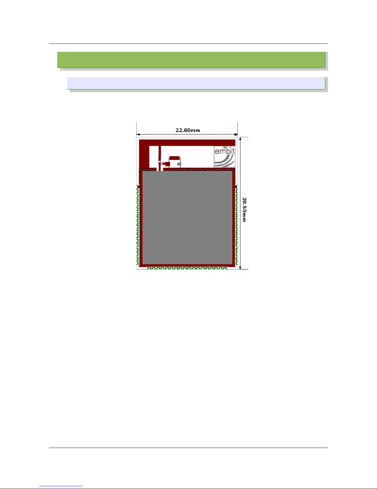
The mechanical dimensions of the EMB- Z2538PA are identical to the dimensions of all
other Embit modules: 29.50 x 22.60 mm. The thickness is 3.6 mm (CAN Shield included).
Image 8: Outline
EMB-Z2538PA Datasheet (rev 1.4) Page 10 of 24
Page 11
Size and footprint
2.2 Connector positioning
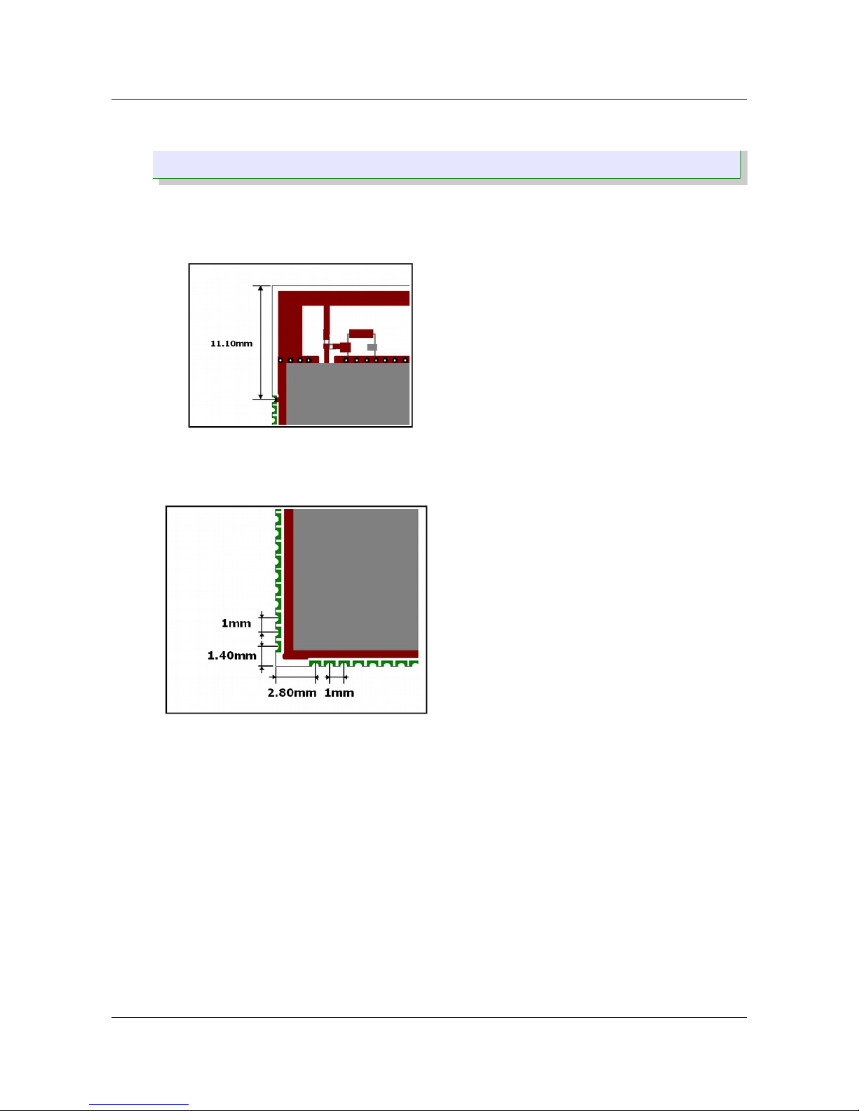
The EMB-Z2538PA module has three 18 pin “edge” connector with a 1.00 mm pitch, for a
sum of 54 contacts. Each pin is a metalized half hole 0.50 mm in diameter. The
positioning of the connector is shown in the following images:
Image 9: Connector positions
Image 10: Connector positions
EMB-Z2538PA Datasheet (rev 1.4) Page 11 of 24
Page 12
Size and footprint
2.3 Footprint
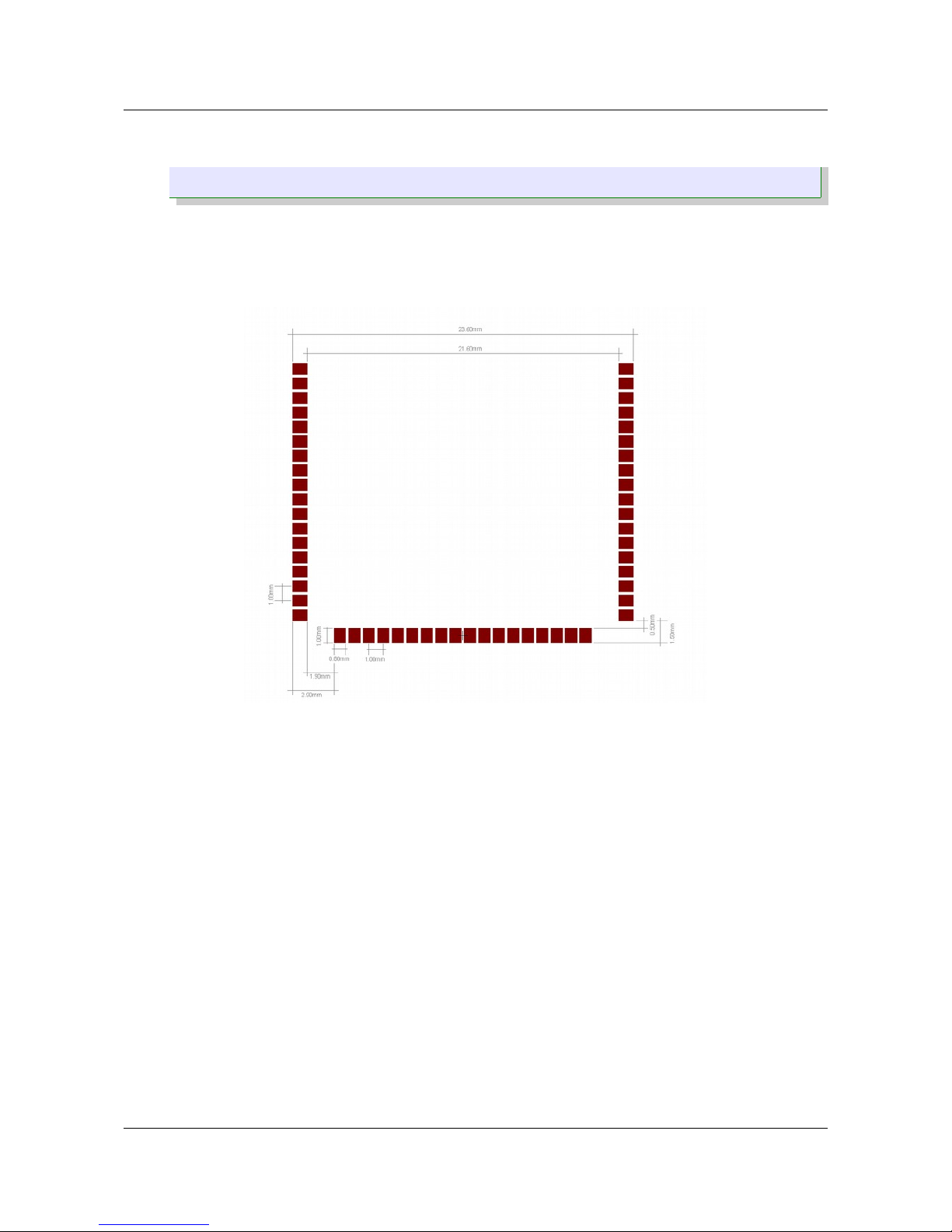
The EMB-Z2538PA footprint consists of 54 SMD pads with size 1.00 x 0.80 mm positioned
as following:
Image 11: Footprint EMB-Z2538PA
Image 12: Pad distribution
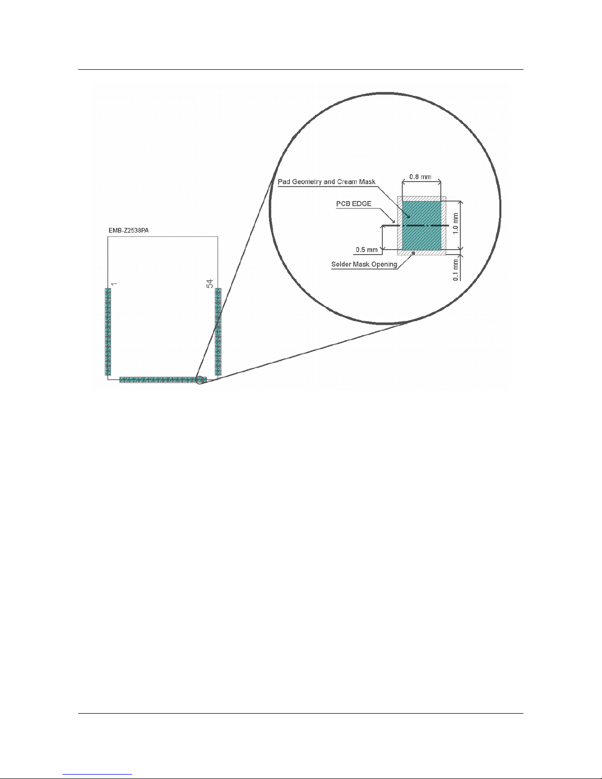
The suggested layout for the pin/pads of the EMB-Z2538PA is shown in the following
image:
EMB-Z2538PA Datasheet (rev 1.4) Page 12 of 24
Page 13
Size and footprint
Image 13: Details of a pin/pad layout
EMB-Z2538PA Datasheet (rev 1.4) Page 13 of 24
Page 14
Size and footprint
2.4 Antenna positioning
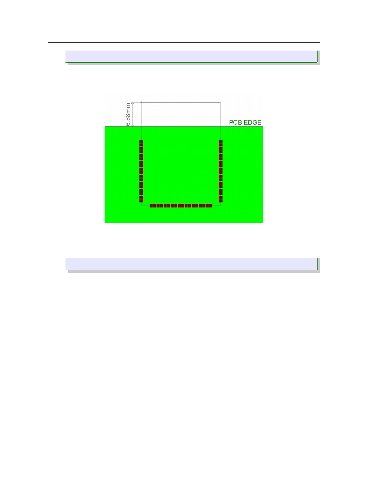
The module must be installed on a PCB, keeping the area dedicated for the PIFA antenna
outside the PCB outline. In the following image is shown an example of installation:
Image 14: Antenna positioning
2.5 Notes
• The area underneath the module must be kept free of components (both top and
bottom layers) and must be covered with solder resist.
• The PCB top layer underneath the module must be free of nets, power planes and
vias. The bottom layer shall provide a ground plane.
• The power supply of the module must be as clean as possible; it must be decoupled
placing a ceramic capacitor as near as possible at the Vcc pins, additional filtering
made by a ferrite bead is recommended.
• Noisy electronic components (such as switching power supply) must be placed as
far as possible and adequately decoupled.
• The ground pins of the module shall be connected to a solid ground plane.
• Keep antenna clear of metal parts of the casing or system.
• Don't use metal enclosures to avoid RF signal degradation.
Note: Taking no account this recommendations may affect the radio performances.
EMB-Z2538PA Datasheet (rev 1.4) Page 14 of 24
Page 15

Connections
3 Connections
3.1 Connections overview
The CC2538 microcontroller allows to route on-chip peripheral to external I/Os through a
muxing matrix. The internal I/O control module allows these peripheral signals to be
routed to or from any of the 32 GPIO pads:
• UART0, UART1
• SSI0 and SSI1
• I2C
• General Purpose Timers 0, 1, 2 and 3
For further information please refer to the Texas Instruments document “CC2538 Systemon-Chip Solution for 2.4-GHz IEEE 802.15.4 and ZigBee®/ZigBee IP® Applications” section
“General-Purpose Inputs/Outputs”.
3.2 Connections Table
Pin # Pin Name Type Description IC Pin #
1 GND GND GND --
2 N.C. Not connected - --
3 N.C. Not connected - --
4 N.C. Not connected - --
5 PA7_ADC0 Analog input or
Digital Input/Output
ADC analog input Channel 7 /
PA7
23
6 PA7_ADC0 Analog input or
Digital Input/Output
ADC analog input Channel 7 /
PA7
23
7 N.C. Not connected - --
8 N.C. Not connected - --
9 N.C. Not connected - --
10 N.C. Not connected - --
11 N.C. Not connected - --
12 N.C. Not connected - --
13 PB7_JTAG_TDO Digital Input/Output JTAG Data Output 48
14 PB6_JTAG_TDI Digital Input/Output JTAG Data Input 49
15 JTAG_TCK Digital Input/Output JTAG Clock 47
16 JTAG_TMS Digital Input/Output JTAG Mode Select 46
17 N.C. Not connected - --
18 VCC Power Input Supply voltage --
19 N.C. Not connected - --
20 PC7_UART2_RX Digital Input/Output UART2 rx data input / PC7 6
21 PC6_UART2_TX Digital Input/Output UART2 tx data output / PC6 7
22 PA3_UART1_RTS Digital Input/Output UART1 request to send input /
PA3
19
EMB-Z2538PA Datasheet (rev 1.4) Page 15 of 24
Page 16

Connections
Pin # Pin Name Type Description IC Pin #
23 PA2_UART1_CTS Digital Input/Output UART1 clear to send output /
PA2
18
24 PA1_UART1_RX Digital Input/Output UART1 rx data input / PA1 17
25 PA0_UART1_TX Digital Input/Output UART1 tx data output / PA0 16
26 N.C. Not connected - --
27 N.C. Not connected - --
28 N.C. Not connected - --
29 N.C. Not connected - --
30 PD2_TMR1 Digital Input/Output Timer IO signal / PD2 27
31 PC1_TMR0 Digital Input/Output Timer IO signal / PC1 13
32 PC1_SPI_SCK Digital Input/Output SPI Port Clock / PC1 13
33 PD1_SPI_MOSI Digital Input/Output SPI Port MOSI / PD1 26
34 PD2_SPI_MISO Digital Input/Output SPI Port MISO / PD2 27
35 PC0_SPI_SS Digital Input/Output SPI Port Slave Select / PC0 14
36 N.C. Not connected - --
37 VCC Power Input Supply voltage --
38 N.C. Not connected - --
39 N.C. Not connected - --
40 N.C. Not connected - --
41 N.C. Not connected - --
42 N.C. Not connected - --
43 PA4_GPIO Digital Input/Output IO (Switch 2) / PA4 20
44 PA5_GPIO Digital Input/Output IO (Switch 1) / PA5 21
45 N.C. Not connected - --
46 N.C. Not connected - --
47 PC0_SPI_SS Digital Input/Output IO (LED2) / PC0 / SPI SS 14
48 PA6_GPIO Digital Input/Output IO (LED1) / PA6 22
49 X32K_Q2 Analog input or
Digital Input/Output
Optional 32,768KHz crystal
oscillator input
45
50 X32K_Q1 Analog output or
Digital Input/Output
Optional 32,768KHz crystal
oscillator output
44
51 RESET# Digital Input System reset input
(active low)
28
52 N.C. Not connected - --
53 N.C. Not connected - --
54 GND GND GND --
EMB-Z2538PA Datasheet (rev 1.4) Page 16 of 24
Page 17
Typical Application Circuit
4 Typical Application Circuit
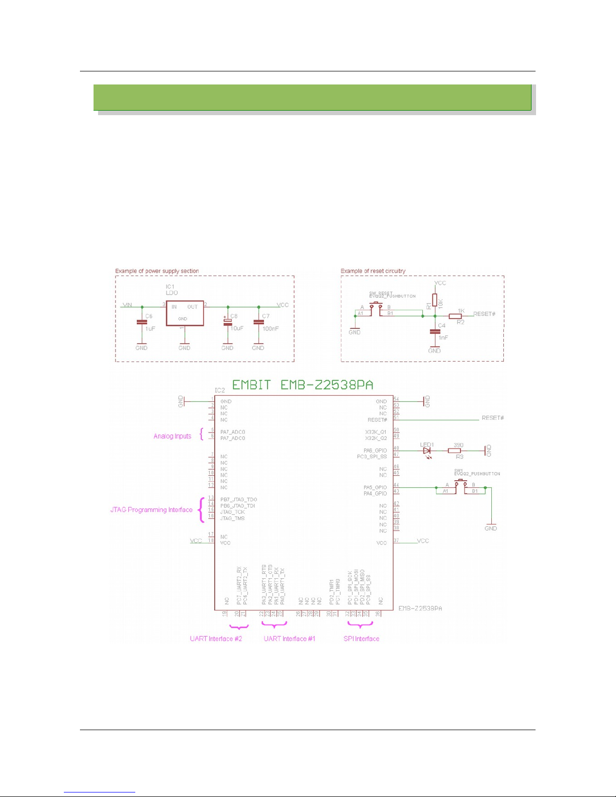
A basic application circuit for the EMB-Z2538PA is shown in Image 15. The EMB-Z2538PA
allows for a minimal number of external components (thus decreasing system costs).
In Image 15 a LED indicator (LED1) and a push button (SW1) are used to provide a minimal
user interface. The JTAG programming/debugging interface, generally speaking, will be
routed to a connector on the host board for in-circuit programming.
In addition, a simple supply section (based on a 3.3V LDO stabilizing the input voltage VIN)
and a simple reset circuitry are shown. In particular, the reset circuitry of Image 15 allows to
1. program the CC2538 MCU of the EMB-Z2538PA (thanks to the weak pull-up to VCC);
2. manually reset the CC2538 MCU, if needed (thanks to SW_RESET).
Image 15: Typical application circuit for the EMB-Z2538PA
EMB-Z2538PA Datasheet (rev 1.4) Page 17 of 24
Page 18
Electrical characteristics
5 Electrical characteristics
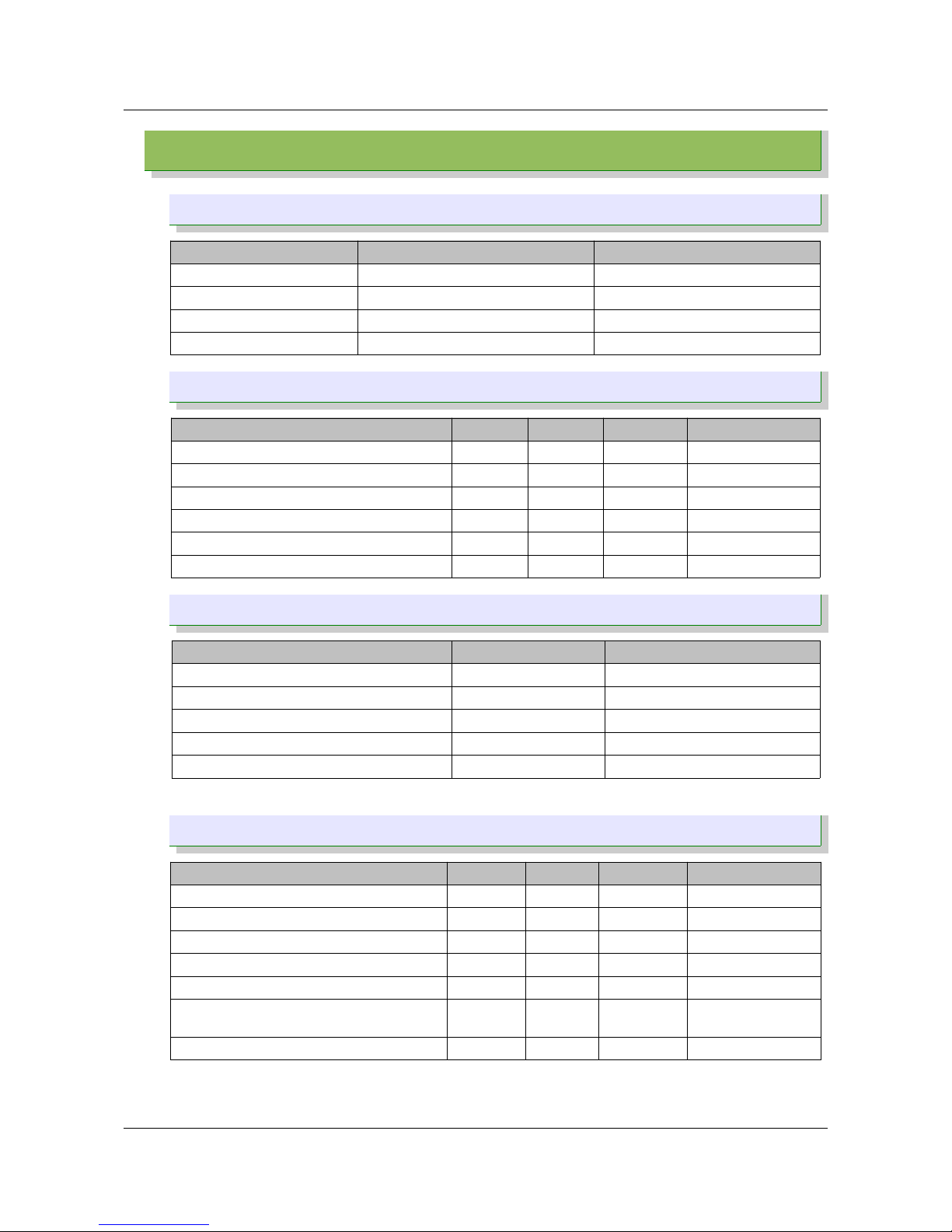
5.1 Absolute Maximum Ratings
Value Unit
Power Supply Voltage +3.6 Vdc
Voltage on any pin Vcc + 0.3 (Max 3.6) Vdc
RF input power (P
MAX
) 10 dBm
Storage Temp. Range -45 ~ +125 ºC
5.2 Operating Conditions
Parameter Min Typ Max Unit
Power Supply Voltage (Vcc) 2.1 3.3 3.6 Vdc
Operating Temperature Range -40 +85 ºC
Logic Input Low Voltage (@ Vdd = 3 V) 0 0.5 Vdc
Logic Input High Voltage (@ Vdd = 3 V) 2.5 Vcc Vdc
Logic Output Low Voltage (@ Vdd = 3 V) 0 0.5 Vdc
Logic Output High Voltage (@ Vdd = 3 V) 2.4 Vcc Vdc
5.3 Power Consumption
Mode Typ. value Unit
Tx @ + 20 dBm (MCU core running @ 32 MHz) 166 mA
Tx @ + 12 dBm (MCU core running @ 32 MHz) 90 mA
Receive (MCU core running) 34.5 mA
Idle (MCU core running, radio off) 15.3 mA
Sleep (MCU core and radio sleeping) Up to 1.7* µA
* 1.7 µA can be obtained in power mode with sleep timer running.
5.4 RF Characteristic
Parameter Min Typ Max Unit
RF Frequency Range 2405 2475 MHz
RF Data Rate 250 kbps
Nominal Output Power -- +10 -- dBm
Programmable Output Power Range +8 -- +22 dBm
Receiver Sensitivity (1% PER) – Normal mode -- -99 -- dBm
Receiver Sensitivity (1% PER) – High sensitivity
mode
-- -101 -- dBm
Saturation (IP3) – Maximum Input Level -2 dBm
EMB-Z2538PA Datasheet (rev 1.4) Page 18 of 24
Page 19
Soldering
6 Soldering
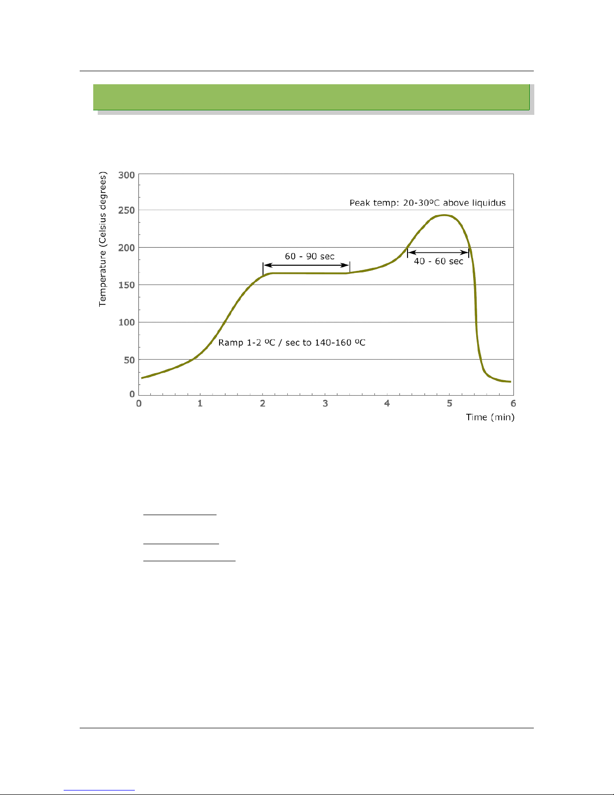
Temperature profile for reflow soldering:
Pb-Free Soldering Paste: it is suggested to used soldering pastes that don't need later
clean for residuals.
Cleaning: it's not suggested to clean the module. Solder paste residuals underneath the
module cannot be removed.
• Water cleaning: the cleaning process using water can involve water entering
underneath the module between the two PCBs creating short circuits.
• Alcohol cleaning: the cleaning process with alcohol can damage the module.
• Ultrasound cleaning: the cleaning process with ultrasound can damage the module.
It is suggested to use no clean solder paste to avoid any need for cleaning.
Cycles: it is suggested to do only one soldering cycle.
In case of reflow soldering, a drying bake should be done in order to prevent a popcorn
effect. Re-baking should be done following IPC standards. Any unused modules that has
been open for more than 168 hours or not stored at <10% RH should be baked before any
subsequent reflow.
EMB-Z2538PA Datasheet (rev 1.4) Page 19 of 24
Page 20

Regulatory Compliance
7 Regulatory Compliance
7.1 Introduction
The purpose of this chapter is to describe which behaviour the user MUST have in order to
operate the device under compliance with current regulations. The details described here
are then to be read carefully and applied literally. Also, please read carefully all the other
documentation available in order to understand all the limits and ensure compliance of
the final application.
The module EMB-Z2538PA is certified for CE and FCC compliance. The different
regulations have different limitations and impose different approaches to the module that
will be discussed in different chapters. Any aspect that both the regulations have in
common will be described in an appropriate chapter in order to keep readability of this
document at maximum.
The main aspect that the user MUST consider is the output power. The module itself is
compliant and ready to be used but care must be taken in setting an appropriate output
power when programming the devices. The module can output up to 22 dBm of conducted
power which translates into up to 20 dBm of EIRP with the integrated antenna or more if
using an external antenna. Please follow the directives in this document to set the
appropriate output power for the antenna you are using. Any other antenna that is not
covered in the certification must not be used unless a new certification is performed.
7.2 Compliance: Important information
The module is to be used in accordance with the current guide. Any hardware
modification on the module will void the certification.
The use of the module is allowed only with the Embit's modified version of the Texas
Instruments software stacks (TIMAC, Z-STACK) on the standard IEEE 802.15.4
channelization (from channel 11 @ 2405 MHz to channel 25 @ 2475 MHz) The channel 26 is
not available due to FCC restrictions. Any modification of the software stack is prohibited.
The antennas used must be one of those indicated by the manufacturer and the output
power must be set as required by the present document.
The EMB-Z2538PA can operate using the internal PIFA antenna or with an external antenna
attached via the U.FL connector. For the specific FCC certification, the list of allowed
antenna are indicated in the following table. The use of any other antenna is permitted
only with a FCC Class two permissive Change.
There is no duty cycle limit for this module if the appropriate power settings are
respected.
The module can only be used with the antennas specified in the following table and the
power setting must not exceed those indicated in this table for each antenna and
operative area (CE or FCC). If the module is using the integrated antenna, please consider
the settings specified for the EMB-AN24-15PFA antenna.
EMB-Z2538PA Datasheet (rev 1.4) Page 20 of 24
Page 21

Regulatory Compliance
Antenna code Antenna type
Antenna
gain
Maximum
tx power
(for CE)
EIRP
(for CE)
Maximum
tx power
(for FCC)
EIRP
(for FCC)
EMB-AN24-15PFA
Integrated Printed PCB
antenna – PIFA
-2 dBi +13 dBm +11 dBm +22 dBm +20 dBm
EMB-AN24-20SA
Omnidirectional swivel
antenna
+2 dBi +9 dBm +11 dBm +22 dBm +24 dBm
EMB-AN24-EA-79F
Omnidirectional swivel
antenna
+3 dBi +8 dBm +11 dBm +22 dBm +25 dBm
EMB-AN24-32SA
Omnidirectional swivel
antenna
+3.2 dBi +8 dBm +11 dBm +22 dBm +25 dBm
EMB-AN24-50SA_R1
Omnidirectional swivel
antenna
+5 dBi
Not
allowed
- +22 dBm +27 dBm
EMB-AN24-70AN_R1
Omnidirectional swivel
antenna
+7 dBi
Not
allowed
- +22 dBm +29 dBm
7.3 CE: compliance
The EBM-Z2538PA is in compliance with the essential requirements and other relevant
provisions of Directive 1999/5/EC.
The Declaration of Conformity made under Directive 1999/5/EC is available for viewing at
the following location in the EU community:
Embit s.r.l.
via Emilia Est, 911
41122 Modena (MO)
Italy
7.4 CE: Output power
The CE regulation allows for up to 20 dBm of EIRP output power but imposes a maximum
power spectral density of +10 mW/MHz. Considering the bandwidth of the IEEE 802.15.4
and ZigBee, this translates into a reduction of the maximum usable output power. Also
spurious emission regulations might impose a lower output power. Consider the antennas
table from previous chapter for setting the right output power.
7.5 FCC: Data
FCC ID: Z7H-EMB2538PA
Brand: Embit
Model: EMB-Z2538PA
Power supply: 2 to 3.6 VDC
EMB-Z2538PA Datasheet (rev 1.4) Page 21 of 24
Page 22

Regulatory Compliance
Transmission frequency: 2405 – 2475 MHz
Other certifications: CE
The device complies with part 15 of the FCC Rules. Operation is subjected to the following
2 conditions: (1) this device may not cause harmful interference and (2) this device must
accept any interference received, including interference that may cause undesired
operation.
This equipment has been tested and found to comply with the limits for a Class B digital
device, pursuant to Part 15 of the FCC Rules. These limits are designed to provide
reasonable protection against harmful interference in a residential installation. This
equipment generates, uses and can radiate radio frequency energy and, if not installed
and used in accordance with the instructions, may cause harmful interference to radio
communications. However, there is no guarantee that interference will not occur in a
particular installation. If this equipment does cause harmful interference to radio or
television reception, which can be determined by turning the equipment off and on, the
user is encouraged to try to correct the interference by one or more of the following
measures:
• Reorient or relocate the receiving antenna.
• Increase the separation between the equipment and receiver.
• Connect the equipment into an outlet on a circuit different from that to which the
receiver is connected.
• Consult the dealer or an experienced radio/TV technician for help.
This equipment is approved only for mobile and base station transmitting devices,
separation distances of (i) 20 centimeters or more for antennas with gains < 6 dBi or (ii) 2
meters or more for antennas with gains ≥ 6 dBi should be maintained between the antenna
of this device and nearby persons during operation. To ensure compliance, operation at
distances closer than this is not recommended.
7.6 FCC: Maximum Output power
The FCC regulation allows for up to 30 dB or output power plus up to 6 dBi of assembly
gain which translates into up to +36 dBm of EIRP. The modules EMB-Z2538PA can output
up to +22 dBm and so, when using the allowed antennas (maximum +14 dBi Gain), will
have no problems with the output power limit. Spurious emission and spectral density
doesn't limit the output power neither on the EMB-Z2538PA and so every output power
setting can be used.
7.7 FCC: Channelization
The IEEE 802.15.4 channel 26 at 2480 MHz is not available due to regulations limitations
on the radio spectrum. The Embit firmware stack does not allow to set the channel 26.
EMB-Z2538PA Datasheet (rev 1.4) Page 22 of 24
Page 23
Ordering information
8 Ordering information
8.1 Types
Module variations:
Part No. Description
EMB-Z2538PA/IA EMB-Z2538PA integrated PIFA antenna
EMB-Z2538PA/UL EMB-Z2538PA U.FL connector for external antenna
Related products:
Part No. Description
EMB-Z2538PA-EVK EMB-Z2538PA Evaluation Kit
8.2 Packaging
Embit's modules are delivered in tubes, each tube including 20 items.
The tube dimensions are approximately: 508mm x 33mm x 8mm.
EMB-Z2538PA Datasheet (rev 1.4) Page 23 of 24
Page 24
Disclaimer
9 Disclaimer
The user must read carefully all the documentation available before using the product. In
particular, care must be taken in order to comply with the regulations (i.e. power limits, duty
cycle limits, etc.).
9.1 Handling precautions
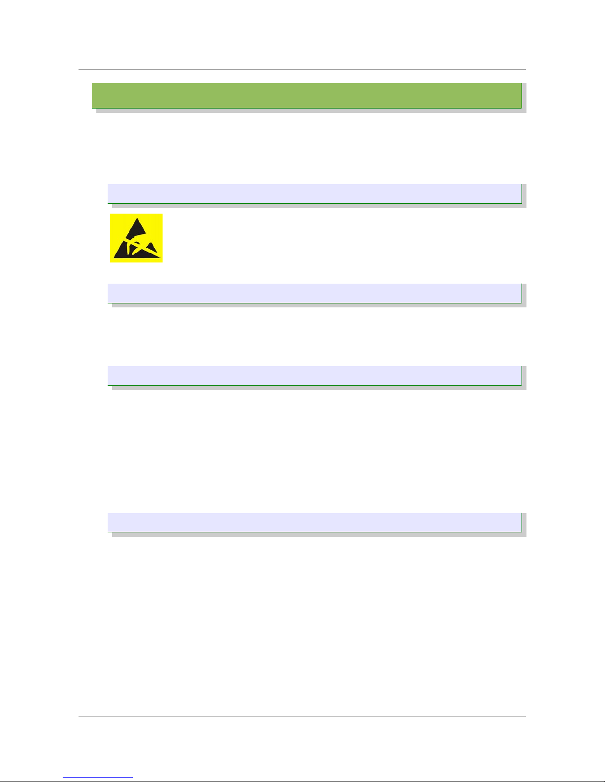
This product is an ESD sensitive device. Handling precautions should be
carefully observed.
9.2 Limitations
Every operation involving a modification on the internal components of the module will
void the warranty.
9.3 Disclaimer of liability
The information provided in this and other documents associated to the product might
contain technical inaccuracies as well as typing errors. Regulations might also vary in
time. Updates to these documents are performed periodically and the information
provided in these manuals might change without notice. The user is required to ensure
that the documentation is updated and the information contained is valid. Embit reserves
the right to change any of the technical/functional specifications as well as to discontinue
manufacture or support of any of its products without any written announcement.
9.4 Trademarks
Embit is a registered trademark owned by Embit s.r.l.
All other trademarks, registered trademarks and product names are the sole property of
their respective owners.
EMB-Z2538PA Datasheet (rev 1.4) Page 24 of 24
 Loading...