

Page 1
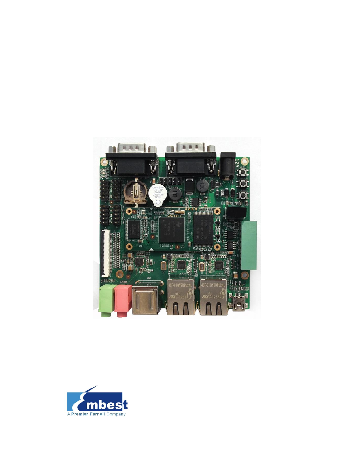
SBC8600B
Single Board Computer
Quick Start Guide
Version 1.1
23rd Jan 2014
Page 2

Copyright Statement:
SBC8600B and its related intellectual property are owned by
Shenzhen Embest Technology Co., Ltd.
Shenzhen Embest Technology has the copyright of this document and
reserves all rights. Any part of the document should not be modified,
distributed or duplicated in any approach and form without prior
written permission issued by Embest Technology Co., Ltd.
Revision History:
Version
Date
Description
1.0
21/12/2012
Original Version
1.1
23/01/2014
Localisation
Page 3

Table of Contents
1 Product Overview .............................................................. 1
2 Quick Start Guide .............................................................. 2
2.1 For Hardware Development: ............................................. 2
2.2 For Software Development: .............................................. 2
2.3 For Marketing: ................................................................ 3
2.4 For Learning: .................................................................. 3
2.5 Kit Contents .................................................................... 4
3 Establishing a Development Environment.......................... 5
3.1 Establishment of Hardware Environment ............................ 5
3.2 Establishment of Software Environment ............................. 6
3.2.1 Preparation of Windows XP System Environment ........................... 6
4 Operating System Quick Start Guide ............................... 10
4.1 Quick operation of the Linux system ................................ 10
4.1.1 Booting from a TF card ............................................................. 10
4.1.2 Boot-up From NAND Flash ........................................................ 14
4.1.3 U-boot configuration ................................................................ 16
4.2 Quick Operation of the WinCE System .............................. 17
4.2.1 Boot-up From TF Card .............................................................. 17
4.2.2 Booting-up From NAND Flash .................................................... 22
4.3 Quick Operation of the Android System ............................ 23
Appendix 1: ESD Precautions & Handling Procedures ......... 25
Appendix 2: Technical support & Warranty ........................ 26
2.1 Technical support service ................................................ 26
2.2 Maintenance service clause ............................................. 27
Page 4

2.3 Basic guidelines for protection and maintenance of LCDs .... 28
2.4 Value Added Services ..................................................... 29
Page 5
Page | 1
1 Product Overview
The primary purpose of this document is to give users an overview of the
software and hardware development environment of the SBC8600B, and to
help the user to start their development or to learn faster.
This document will cover the following points:
Where to find the useful contents for different requirements;
Packing list and DVD contents;
Default configuration of software and hardware of the Single Board
Computer;
Building a development environment for the Single Board Computer
quickly;
Booting up Linux/wince/Android operating systems quickly.
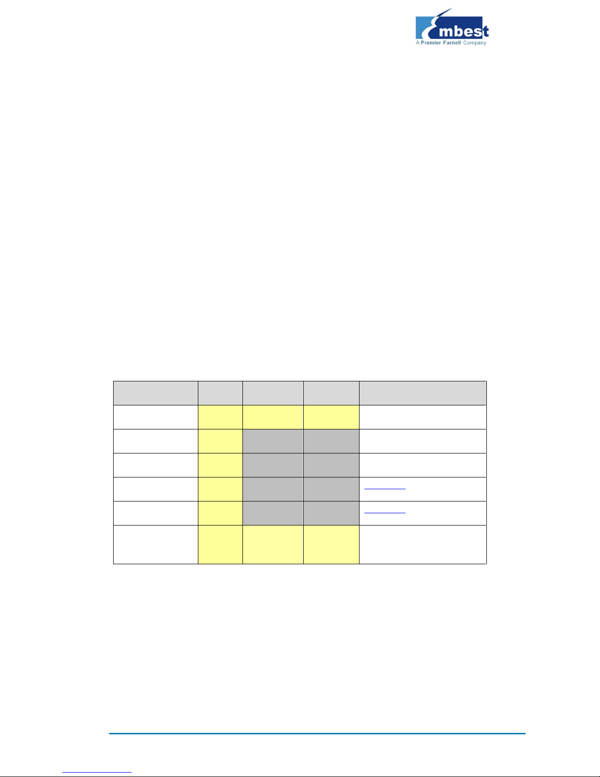
SBC8100 Plus Optional Modules List:
Names
Linux
Android
WinCE
Relevant Materials
VGA8000
YES
YES
YES
Available in DVD-ROM
WF8000-U
YES
NO
NO
Available in DVD-ROM
CAM8100-U
YES
NO
NO
Available in DVD-ROM
CDMA8000-U
YES
NO
NO
Download
WCDMA8000-U
YES
NO
NO
Download
LVDS8000
YES
YES
YES
Available in DVD-ROM and
on website
Page 6
Page | 2
2 Quick Start Guide
This section contains several tables that indicate where to find the useful
contents for different requirements, so users may get to work quickly!
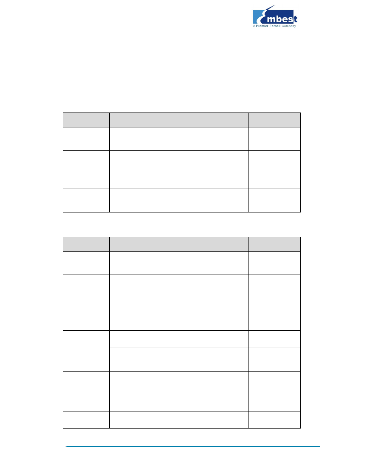
2.1 For Hardware Development:
Item
Description
Location
Hardware
system
Introduces CPU, peripheral chips and hardware
interfaces
User Manual
CPU Datasheet
Shows principles and configuration of AM3359x
DVD
Schematic of
SBC8600B
Contains hardware principles of SBC8600B
DVD
Dimensions of
SBC8600B
The actual dimensions of SBC8600B used to aid in
manufacturing
User Manual
2.2 For Software Development:
Item
Description
Location
Preparations for
testing
Connecting external devices, setting up
HyperTerminal and booting up the system
Quick Start Guide
Testing
functionalities
of interfaces
Testing the interfaces on the board via an operating
system
User Manual
DEMO
demonstration
Establish a demonstration system (Android, TISDK)
User Manual
Establish
developing and
compilation
environment
Linux development and compilation environment
User Manual
Windows Embedded Compact 7 development and
compilation environment
User Manual
Recompile
system image
Recompiling Linux system image
User Manual
Recompiling Windows Embedded Compact 7 system
image
User Manual
Software
Introduction to Linux drivers and related driver
User Manual
Page 7
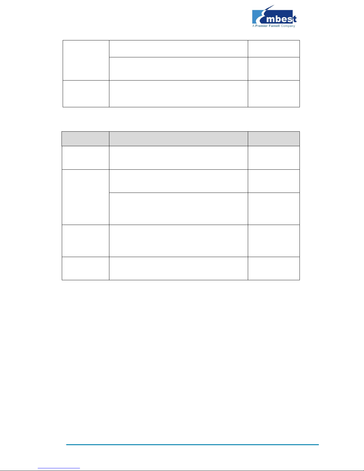
Page | 3
development
development processes
Introduction to Windows Embedded Compact 7
drivers and related driver development processes
User Manual
StarterWare
Describes bare-metal programming and example
execution
DVD
2.3 For Marketing:
Item
Description
Location
Hardware
system
CPU features and information about on-board
interfaces
User Manual
Software of
Linux / Windows
Embedded
Compact 7
Teaches basic Linux software components and
features, and the purpose of the compilation tool
User Manual
Teaches about the basic software components of
Windows Embedded Compact 7 and their features,
and the purpose of the compilation tool
User Manual
Dimensional
drawing of
SBC8600B
The actual dimensions of SBC8600B used to aid in
manufacturing
User Manual
DEMO
demonstration
Establish a demonstration system (Android, TISDK)
User Manual
2.4 For Learning:
It is recommended to read each part of this Manual from the beginning to
the end.
Page 8

Page | 4
2.5 Kit Contents
SBC8600B Single Board Computer(with Mini8600B)
Serial Cable (DB9-DB9)
12V, 1.25A Power Adapter
Crossover Cable
Optional 4.3” LCD display screen or 7” display screen (with touch
screen)
DVD/CD including:
o SBC8600B Quick Operation Manual
o SBC8600B User Manual
o SBC8600B Starterware User Manual
o Schematic Diagram of SBC8600B Hardware, Board Carrier
Chip Datasheet
o Development Kit of SBC8600B Software (
Linux/WinCE/Android/Starterware)
Page 9
Page | 5
3 Establishing a Development
Environment
3.1 Establishment of Hardware Environment
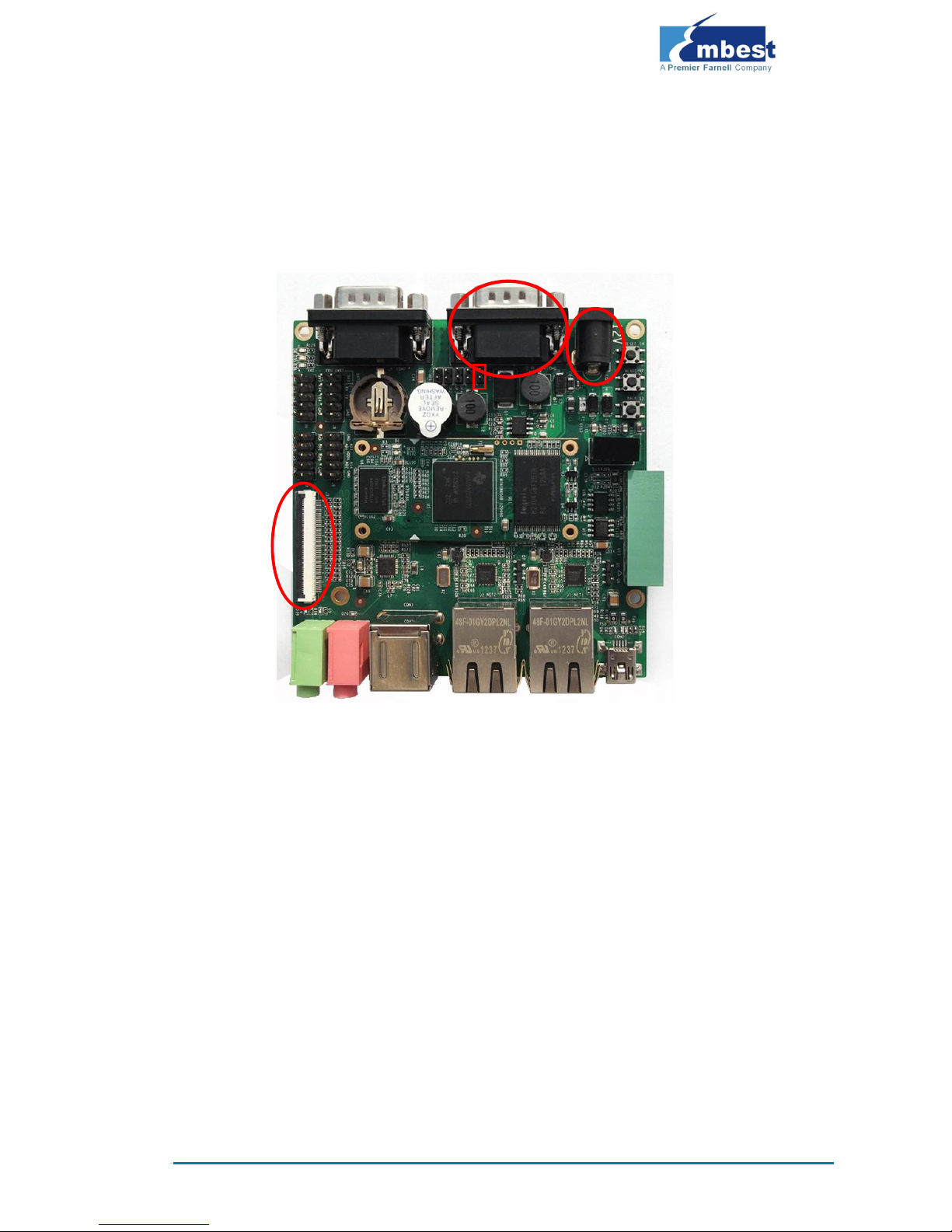
Figure 1: SBC8600B Hardware Connections
Please establish the hardware environment according to the following steps:
1. Connect Touch-Screen LCD
2. Connect your 4.3-inch/7-inch touch-screen LCD to the LCD
interface, and keep the blue side of the FPC cable up
3. Connect Serial Ports
4. Use serial cable to connect the PC serial port to the debugger
serial port of SBC8600B.
5. If you want to boot from a TF card, you need to short the jumper
JP5
6. Connect the 12V power adapter to the evaluation board
1
2
4
JP5
Page 10

Page | 6
3.2 Establishment of Software Environment
3.2.1 Preparation of Windows XP System Environment
Before powering up SBC8600B, you need to configure HyperTerminal on the
PC, follow the process below in order to setup a Hyper Terminal connection:
1. From the desktop click:
Start
All Programs
Accessories
Communication
Hyper Terminal
As shown in the following image:
Figure 2: HyperTerminal Location on Windows XP
Page 11

Page | 7
2. Establish a new HyperTerminal connection:
Figure 3: Setting HyperTerminal Connection Name & Icon
3. Select the specific serial port from the list as per your computers
COM port configuration:
Figure 4: HyperTerminal COM Port Settings
Page 12

Page | 8
4. Set parameters for the serial port connection as follows:
Figure 5: HyperTerminal Connection Settings
5. The following image shows that we have successfully established
a Hyper Terminal connection with the PC’s serial port:
Figure 6: Successful HyperTerminal Connection
Page 13

Page | 9
Note:
If you have a 7-inch touch screen, you can change the settings in UBOOT
according to the detailed instructions contained in User Manual
Now we have successfully established both a software and a hardware
environment for the system. We can turn on the power switch to start the
development on SBC8600B.
Page 14

Page | 10
4 Operating System Quick Start
Guide
The SBC8600B supports three operating systems: Linux 3.2.0, WinCE6.0
and Android. This chapter mainly introduces how to switch between different
operating systems and how to boot up from a TF card and NAND Flash.
4.1 Quick operation of the Linux system
4.1.1 Booting from a TF card
Formatting TF Card
HP USB Disk Storage Format Tool 2.0.6 is recommended as the formatting
tool. Please download it from:
http://www.embest-tech.com/resource/download/HP-USB-Disk-St
orage-Format-Tool.rar
1. Insert TF card into a card reader and then insert the reader into
your PC.
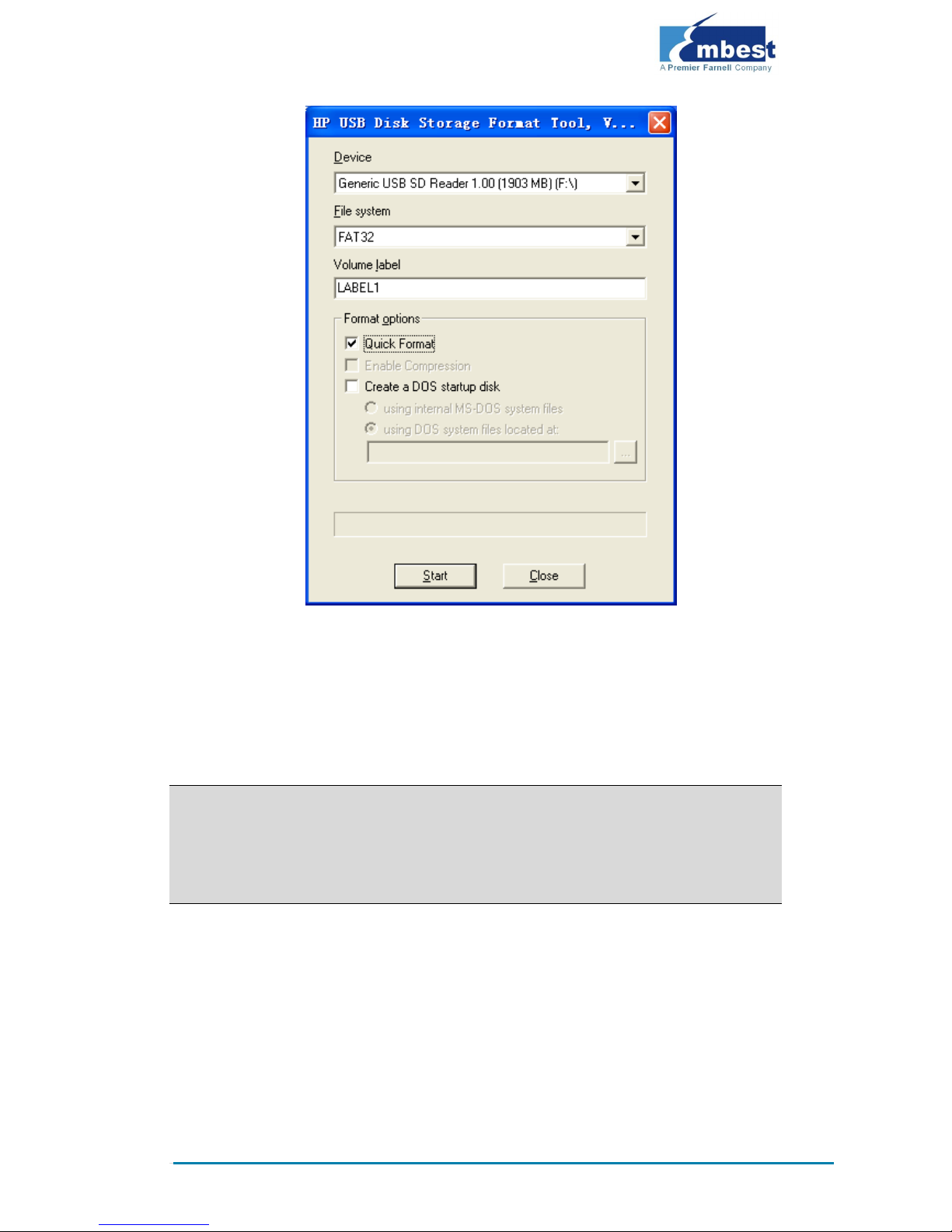
2. Open the HP USB Disk Storage Format Tool to show the following
window:
Page 15
Page | 11
3. Select “FAT32” file system
4. Click “Start”
5. When formatting is complete, click “OK”
Note:
HP USB Disk Storage Format Tool will erase the partitions of TF card.
Use other format tool may cause the failure of the TF card booting.
Image Update
Copy all files under the directory linux\image to the TF card, insert it on the
board, and then power up the board. The information on serial interface will
be shown as below:
Page 16

Page | 12
Note:
The default display is a 4.3” LCD. If you are working with LCDs of another size,
please enter u-boot when the board is booting up to configure the display mode,
and then type boot to continue boot-up process. Please refer to the User Manual
for more details
If there is already an image in NAND Flash, you need to short the jumper JP5 on
the board so as to make it boot up from TF card. Disconnect JP5 after successful
boot-up of the system.
Booting from MMC...
OMAP SD/MMC: 0
reading u-boot.img
reading u-boot.img
U-Boot 2011.09-svn55 (Dec 04 2012 - 09:29:02)
I2C: ready
DRAM: 512 MiB
WARNING: Caches not enabled
Did not find a recognized configuration, assuming General
purpose EVM in Profile 0 with Daughter board
NAND: HW ECC Hamming Code selected
512 MiB
MMC: OMAP SD/MMC: 0
*** Warning - bad CRC, using default environment
Net: cpsw
Hit any key to stop autoboot: 0
SD/MMC found on device 0
reading uEnv.txt
** Unable to read "uEnv.txt" from mmc 0:1 **
reading uImage
3224184 bytes read
reading ramdisk.gz
12514633 bytes read
## Booting kernel from Legacy Image at 80007fc0 ...
Page 17

Page | 13
Image Name: Linux-3.2.0
Image Type: ARM Linux Kernel Image (uncompressed)
Data Size: 3224120 Bytes = 3.1 MiB
Load Address: 80008000
Entry Point: 80008000
Verifying Checksum ... OK
XIP Kernel Image ... OK
OK
Starting kernel ...
Uncompressing Linux... done, booting the kernel.
Linux version 3.2.0 (luofc@TIOP) (gcc version 4.3.3 (Sourcery
G++ Lite 2009q1-203) ) #17 Fri Dec 7 10:04:07 CST 2012
………
………
RAMDISK: gzip image found at block 0
VFS: Mounted root (ext2 filesystem) on device 1:0.
Freeing init memory: 260K
INIT: version 2.86 booting
Starting udevudevd (741): /proc/741/oom_adj is deprecated,
please use /proc/741/oom_score_adj instead.
tar: removing leading '/' from member names
Remounting root file system...
mount: mounting /dev/root on / failed: Invalid argument
mount: mounting /dev/root on / failed: Invalid argument
root: mount: mounting rootfs on / failed: No such file or
directory
Setting up IP spoofing protection: rp_filter.
Configuring network interfaces... udhcpc (v1.11.3) started
Sending discover...
udhcpc: sendto: Network is down
Sending discover...
udhcpc: sendto: Network is down
Sending discover...
udhcpc: sendto: Network is down
No lease, failing
done.
Tue Jan 27 08:47:00 UTC 2009
INIT: Entering runlevel: 5
Starting syslogd/klogd: done
.-------.
Page 18

Page | 14
| | .-.
| | |-----.-----.-----.| | .----..-----.-----.
| | | __ | ---'| '--.| .-'| | |
| | | | | |--- || --'| | | ' | | | |
'---'---'--'--'--. |-----''----''--' '-----'-'-'-'
-' |
'---'
The Angstrom Distribution SBC8600 ttyO0
Angstrom 2008.1-test-20090127 SBC8600 ttyO0
SBC8600 login: (Type ”root”)
The above information indicates a successful boot-up of Linux from the TF
card.
4.1.2 Boot-up From NAND Flash
Updating of the NAND boot-up image is accomplished by u-boot. Regardless
of whether NAND Flash contains data, u-boot can be used to update any
NAND Flash images.
Preparation
1. Format the TF card to a FAT or FAT32 file system by using the HP
USB Disk Storage Format Tool 2.0.6
2. Copy the files MLO, u-boot.img, uImage and ubi.img under
the directory linux\image from DVD-ROM into a TF card.
Update
3. Insert the TF card which contains the system images into the
development board, and then connect the power supply. Press
any key on the keyboard to enter u-boot when the message "Hit
any key to stop autoboot" appears:
Page 19

Page | 15
Note:
You may short the jumper JP5 on the board to allow SBC8600B boot up from TF
card and enter u-boot to write the image in NAND Flash, and then disconnect
JP5 to allow system boot up from NAND Flash.
Alternatively, you may leave JP5 disconnected and insert the TF card on the
board to boot up from NAND Flash, and then write the image in NAND Flash
through uboot.
U-Boot SPL 2011.09-svn55 (Nov 20 2012 - 10:37:42)
Texas Instruments Revision detection unimplemented
Booting from MMC...
OMAP SD/MMC: 0
reading u-boot.img
reading u-boot.img
U-Boot SPL 2011.09-svn55 (Nov 20 2012 - 10:37:42)
I2C: ready
DRAM: 512 MiB
WARNING: Caches not enabled
Did not find a recognized configuration, assuming General
purpose EVM in Profile 0 with Daughter board
NAND: HW ECC Hamming Code selected
512 MiB
MMC: OMAP SD/MMC: 0
*** Warning - bad CRC, using default environment
Net: cpsw
Hit any key to stop autoboot: 0 (press any key to enter uboot)
4. After entering the u-boot command line, type “run updatesys” to
start the update process of the system:
SBC8600# run updatesys
NAND erase.chip: device 0 whole chip
Erasing at 0x7fe0000 -- 100% complete.
OK
reading MLO
36079 bytes read
Page 20

Page | 16
HW ECC BCH8 Selected
NAND write: device 0 offset 0x0, size 0x8cef
36079 bytes written: OK
reading u-boot.img
234896 bytes read
HW ECC BCH8 Selected
NAND write: device 0 offset 0x80000, size 0x39590
234896 bytes written: OK
reading uImage
3224184 bytes read
HW ECC BCH8 Selected
NAND write: device 0 offset 0x280000, size 0x313278
3224184 bytes written: OK
reading ubi.img
14811136 bytes read
SW ECC selected
NAND write: device 0 offset 0x780000, size 0xe20000
Skip bad block 0x00ce0000
14811136 bytes written: OK
A Flashing LED on the board indicates that the update has been finished;
please remove the TF card and reboot the board.
4.1.3 U-boot configuration
The system image is set by default for a 4.3” LCD. You can change the
settings in UBOOT by using the instructions contained within the User
Manual.
Page 21
Page | 17
4.2 Quick Operation of the WinCE System
4.2.1 Boot-up From TF Card
Formatting TF Card
HP USB Disk Storage Format Tool 2.0.6 is recommended as the formatting
tool. Please download it from:
http://www.embest-tech.com/resource/download/HP-USB-Disk-St
orage-Format-Tool.rar
1. Insert TF card into a card reader and then insert the reader into
your PC.
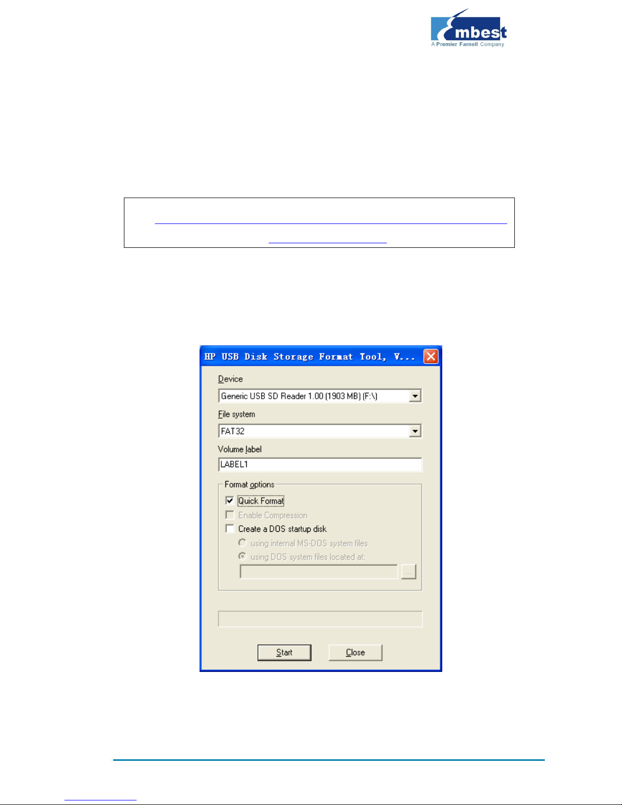
2. Open the HP USB Disk Storage Format Tool to show the following
window:
3. Select “FAT32” file system
4. Click “Start”
Page 22

Page | 18
5. When formatting is complete, click “OK”
Note:
HP USB Disk Storage Format Tool will erase the partitions of TF card.
Use other format tool may cause the failure of the TF card booting.
Copy Runtime Image
Copy the MLO, EBOOTSD.nb0 and NK.bin image files to the TF card. They
are located under CD\WINCE700\image
System Boot-up
Insert a TF card, reboot the system from the TF card and press Space in a
few seconds to enter to the EBOOT menu as shown below:
6. Enter the EBOOT Menu
CCCCCCCC
Texas Instruments Windows CE SD X-Loader33X
Built Jul 27 2012 at 11:25:59
Version BSP_WINCE_ARM_A8 02.30.00.03
open ebootsd.nb0 file
Init HW: controller RST
SDCARD: requested speed 1000000, actual speed 1000000
SDCARD: requested speed 25000000, actual speed 19200000
read ebootsd.nb0 file
jumping to ebootsd image
Microsoft Windows CE Bootloader Common Library Version 1.4 Built
Jul 27 2012 11:23:05
I2C EEPROM returned wrong magic value 0xffffffff
INFO:OALLogSetZones: dpCurSettings.ulZoneMask: 0x8409
Texas Instruments Windows CE EBOOT for AM33x, Built Jul 27 2012
at 11:25:53
EBOOT Version 0.0.1, BSP BSP_WINCE_ARM_A8 02.30.00.03
AHCLKX pinmux:0
AHCLKX CTRL:0x8001
Page 23

Page | 19
pin function:0x0
pin dir:0x8000000
TI AM33X
ecc type:3
System ready!
Preparing for download...
INFO: Predownload....
Checking bootloader blocks are marked as reserved (Num = 18)
BOOT_CFG_SIGNATURE is different, read -1, expect 1111705159
WARN: Boot config wasn't found, using defaults
INFO: SW3 boot setting: 0x04
IsValidMBR: MBR sector = 0x480 (valid MBR)
OpenPartition: Partition Exists=0x1 for part 0x20.
>>> Forcing cold boot (non-persistent registry and other data
will be wiped) <<<
e0311800 56e4 -> 0 18 31 e0 e4 56
e0311800 57e4 -> 0 18 31 e0 e4 57
Hit space to enter configuration menu [56] 5...(press SPACE to
enter EBOOT menu)
7. Type [2]->[2] to set the board to boot up from the TF card
-----------------------------------------------------------
---------------------
Main Menu
-----------------------------------------------------------
---------------------
[1] Show Current Settings
[2] Select Boot Device
[3] Select KITL (Debug) Device
[4] Network Settings
[5] SDCard Settings
[6] Set Device ID
[7] Save Settings
[8] Flash Management
[9] Enable/Disable OAL Retail Messages
[a] Select Display Resolution
[b] Select OPP Mode
[0] Exit and Continue
Selection: 2
Page 24

Page | 20
-----------------------------------------------------------
---------------------
Select Boot Device
-----------------------------------------------------------
---------------------
[1] Internal EMAC
[2] NK from SDCard FILE
[3] NK from NAND
[0] Exit and Continue
Selection (actual Internal EMAC): 2
Boot device set to NK from SDCard FILE
8. Type [a] to enter “Select Display Resolution” menu and select
LCD\LVDS as the output
-----------------------------------------------------------
---------------------
Main Menu
-----------------------------------------------------------
---------------------
[1] Show Current Settings
[2] Select Boot Device
[3] Select KITL (Debug) Device
[4] Network Settings
[5] SDCard Settings
[6] Set Device ID
[7] Save Settings
[8] Flash Management
[9] Enable/Disable OAL Retail Messages
[a] Select Display Resolution
[b] Select OPP Mode
[0] Exit and Continue
Selection: a
-----------------------------------------------------------
---------------------
Select Display Resolution
-----------------------------------------------------------
---------------------
[1] LCD 480x272 60Hz //For 4.3-inch LCD
[2] DVI 640x480 60Hz(N/A)
[3] DVI 640x480 72Hz(N/A)
Page 25

Page | 21
[4] LCD 800x480 60Hz //For 7-inch LCD
[5] DVI 800x600 60Hz(N/A) //For LVDS
[6] DVI 800x600 56Hz(N/A)
[7] VGA 1024x768 60Hz //For VGA
[8] DVI 1280x720 60Hz(N/A)
[0] Exit and Continue Selection (actual LCD 480x272 60Hz): 4
9. Type [0] to continue the boot-up process
-----------------------------------------------------------
---------------------
Main Menu
-----------------------------------------------------------
---------------------
[1] Show Current Settings
[2] Select Boot Device
[3] Select KITL (Debug) Device
[4] Network Settings
[5] SDCard Settings
[6] Set Device ID
[7] Save Settings
[8] Flash Management
[9] Enable/Disable OAL Retail Messages
[a] Select Display Resolution
[b] Select OPP Mode
[0] Exit and Continue
Selection: 0
mode = 3
LcdPdd_LCD_GetMode:3
mode = 3
LcdPdd_LCD_Initialize:3
OEMPreDownload: Filename nk.bin
Init HW: controller RST
SDCARD: requested speed 1000000, actual speed 1000000
SDCARD: requested speed 25000000, actual speed 19200000
BL_IMAGE_TYPE_BIN
+OEMMultiBinNotify(0x8feb24d8 -> 1)
Download file information:
-----------------------------------------------------------
[0]: Address=0x80002000 Length=0x03c9e9bc Save=0x80002000
-----------------------------------------------------------
Download file type: 1
Page 26

Page | 22
+OEMIsFlashAddr(0x80002000) g_eboot.type 1
...........................................................
...........................................................
...........................................................
...........................................................
...........................................................
...............................................rom_offset=0
x0.
..ImageStart = 0x80002000, ImageLength = 0x3c9e9bc, LaunchAddr
= 0x8000b6a0
Completed file(s):
-----------------------------------------------------------
--------------------
+OEMIsFlashAddr(0x80002000) g_eboot.type 1
[0]: Address=0x80002000 Length=0x3c9e9bc Name="" Target=RAM
ROMHDR at Address 80002044h
Launch Windows CE image by jumping to 0x8000b6a0...
Windows CE Kernel for ARM (Thumb Enabled)
CPU CP15 Control Register = 0xc5387f
CPU CP15 Auxiliary Control Register = 0x42
I2C EEPROM returned wrong magic value 0xffffffff
+OALTimerInit(1, 24000, 200)
--- High Performance Frequecy is 24 MHz---
4.2.2 Booting-up From NAND Flash
1. Formatting TF card
Please refer to p17 for instructions
2. Copy runtime image
Copy MLO, EBOOTND.nb0, NK.bin, XLDRNAND.nb0 and
EBOOTSD.nb0 image files under CD\WINCE700\image to the TF card.
3. Update of NAND Flash image files
Insert TF card, reboot the system from TF card and press Space in a few
seconds to enter to the EBOOT menu, and then follow the steps listed below:
Type [8] to enter the Flash menu;
Page 27

Page | 23
Type [9]->[4]->[A], [9]->[3]->[B] and [9]->[2]->[C] to write
XLDR, EBOOT and NK images;
Type [0] to return to the main menu, and then type [2] and [3] to
select boot-up from NAND Flash; Type [A] to select LCD/DVI display
mode; Type [7] and [y] to save the boot-up settings;
Remove the TF card and reboot the system. The system will boot from NAND
Flash.
4.3 Quick Operation of the Android System
The SBC8600B provides an Android system demonstration, please follow the
steps listed below:
1. Copy all files under the directory \linux\demo\Android\image of
the DVD-ROM to a TF card;
2. Insert the TF card on the board and short jumper JP5, and then
power on the board. The debugging tool will show the following
information:
CCCCCCCC
U-Boot SPL 2011.09-svn55 (Dec 04 2012 - 09:36:25)
Texas Instruments Revision detection unimplemented
Booting from MMC...
OMAP SD/MMC: 0
reading u-boot.img
reading u-boot.img
U-Boot 2011.09-svn55 (Nov 22 2012 - 11:35:28)
I2C: ready
DRAM: 512 MiB
WARNING: Caches not enabled
Did not find a recognized configuration, assuming General
purpose EVM in Profile 0 with Daughter board
NAND: HW ECC Hamming Code selected
512 MiB
MMC: OMAP SD/MMC: 0
*** Warning - bad CRC, using default environment
Page 28

Page | 24
NAND erase.chip: device 0 whole chip
Skipping bad block at 0x03620000
Erasing at 0x1ffe0000 -- 100% complete.
OK
reading MLO
36079 bytes read
HW ECC BCH8 Selected
NAND write: device 0 offset 0x0, size 0x8cef
36079 bytes written: OK
reading flash-uboot.img
234620 bytes read
HW ECC BCH8 Selected
NAND write: device 0 offset 0x80000, size 0x3947c
234620 bytes written: OK
reading uImage
2719416 bytes read
HW ECC BCH8 Selected
NAND write: device 0 offset 0x280000, size 0x297eb8
2719416 bytes written: OK
reading ubi.img
72744960 bytes read
SW ECC selected
NAND write: device 0 offset 0x780000, size 0x4560000
72744960 bytes written: OK
3. When the writing process is complete, the on-board LED will be
flashing. Please remove the TF card and the jumper cap. Power
on the board again to load the Android operating system;
Note
The system is set by default for a 4.3” LCD. You can change the settings in
UBOOT according to the instructions contained in the User Manual.
Page 29

Page | 25
Appendix 1: ESD Precautions &
Handling Procedures
Please note that the board comes without any case/box and all components
are exposed. Therefore, extra attention must be paid to ESD (electrostatic
discharge) precautions. To effectively prevent electrostatic damage, please
follow the steps below:
Avoid carpets in cool, dry areas. Leave development
kits in their anti-static packaging until ready to be
installed.
Dissipate static electricity before handling any system components
(development kits) by touching a grounded metal object, such as the
system unit unpainted metal chassis.
If possible, use antistatic devices, such as wrist straps and floor mats.
Always hold an evaluation board by its edges. Avoid touching the
contacts and components on the board.
Take care when connecting or disconnecting cables. A damaged cable
can cause a short in the electrical circuit.
Prevent damage to the connectors by aligning connector pins before
you connect the cable. Misaligned connector pins can cause damage
to system components at power-on.
When disconnecting a cable, always pull on the cable connector or
strain-relief loop, not on the cable itself.
Warning:
This is a class A product. In a domestic environment this product may cause
radio interference in which case the user may be required to take adequate
measures.
Page 30

Page | 26
Appendix 2: Technical support &
Warranty
Embest Technology Co., Ltd. established in March of 2000, is a global
provider of embedded hardware and software. Embest aims to help
customers reduce time to market with improved quality by providing the
most effective total solutions for the embedded industry. In the rapidly
growing market of high end embedded systems, Embest provides
comprehensive services to specify, develop and produce products and help
customers to implement innovative technology and product features.
Progressing from prototyping to the final product within a short time frame
and thus shortening the time to market, and to achieve the lowest
production costs possible. Embest insists on a simple business model: to
offer customers high-performance, low-cost products with the best quality
and service.
2.1 Technical support service
Embest provides one year of free technical support for all products. The
technical support service covers:
Embest embedded platform products software/hardware materials
Assistance to customers with regards to compiling and running the
source code we offer.
Troubleshooting problems occurring on embedded
software/hardware platforms if users have followed the instructions
provided.
Judge whether a product failure exists.
The situations listed below are not covered by our free technical support
service, and Embest will handle the situation at our discretion:
Customers encounter issues related to software or hardware during
their development process
Issues occur when users compile/run the embedded OS which has
been modified by themselves.
Page 31

Page | 27
Customers encounter issues related to their own applications.
Customers experience problems caused by unauthorised alteration of
our software source code
2.2 Maintenance service clause
1. Product warranty will commence on the day of sale and last 12
months provided the product is used under normal conditions
2. The following situations are not covered by the warranty,
Embest will charge service fees as appropriate:
Customers fail to provide valid proof of purchase or the product
identification tag is damaged, unreadable, altered or inconsistent with
the product.
Products are subject to damage caused by operations inconsistent
with their specification;
Products are subject to damage in either appearance or function due
to natural disasters (flood, fire, earthquake, lightning strike or
typhoon) or natural aging of components or other force majeure;
Products are subject to damage in appearance or function due to
power failure, external forces, water, animals or foreign materials;
Products malfunction due to disassembly or alteration of components
by customers, or repair by persons or organizations unauthorized by
Embest Technology, or alteration from factory specifications, or
configured or expanded with components that are not provided or
recognized by Embest Technology;
Product failures due to the software or systems installed by
customers, inappropriate software settings or computer viruses;
Products purchased from unauthorized merchants;
Page 32

Page | 28
Embest Technology takes no responsibility for fulfilling any warranty
(verbal or written) that is not made by Embest Technology and not
included in the scope of our warranty.
3. Within the period of warranty, the cost for sending products to
Embest should be paid by the customer. The cost for returning
the product to the customer will be paid by Embest. Any returns
in either direction occurring after the warranty period has
expired should be paid for by the customer.
4. Please contact technical support with any repair requests.
Note:
Embest Technology will not take any responsibility for products returned
without the prior permission of the company.
2.3 Basic guidelines for protection and
maintenance of LCDs
1. Do not use finger nails or other hard sharp objects to touch the
surface of the LCD
2. Embest recommends purchasing specialist wipes to clean the
LCD after long time use, avoid cleaning the surface with fingers
or hands as this may leave fingerprints or smudges.
3. Do not clean the surface of the screen with unsuitable chemicals
Note:
Embest do not supply a maintenance service for LCDs. We suggest the
customer immediately checks the LCD once in receipt of the goods. In the event
that the LCD does not run or shows no display, the customer should inform
Embest within 7 business days of delivery.
Page 33

Page | 29
2.4 Value Added Services
We will provide following value added services:
Driver development based on Embest embedded platforms for
devices such as: serial ports, USB interface devices, and LCD screens.
Control system transplantation, BSP driver development, API
software development.
Other value added services including supply of power adapters and
LCD parts.
Other OEM/ODM services.
Technical training.
Please contact Embest with any technical support queries:
http://www.embest-tech.com/contact-us.html
 Loading...