

EmberGlow VMO24RNGA Owner's Operation And Installation Manual

Convertible from Natural Gas to Propane/LP Gas
OWNER'S OPERATION AND INSTALLATION MANUAL
WARNING: If the information in this manual is not
followedexactly,a fire or explosion may resultcausing
property damage, personal injury or loss of life.
—
Do not store or use gasoline or other flammable vapors
and liquids in thevicinity of this or any other appliance.
— WHAT TO DO IF YOU SMELL GAS
• Do not try to light any appliance.
• Donottouchanyelectricalswitch;donotuseany
phone in your building.
• Immediatelycallyourgassupplierfromaneighbor’s
phone. Follow the gas supplier’s instructions.
• If you cannot reach your gas supplier,call the fire
department.
— Installationandservicemustbeperformedbyaquali-
fied installer, serviceage
ncy or the gassupplier.
INSTALLER: Leave this manual with the appliance.
CONSUMER: Retain this manual for future reference.
Vented Decorative Appliances
for installation in Solid Fuel
VMO24RNGA
Burning Fireplaces
For Use with
APPALACHIAN OAK LOGS
REMOTE CONTROL GAS LOG
VENTED DECORATIVE APPLIANCE
Tested &
Listed By
Safety
...............................................................
Product Identification
Local Codes
Unpacking
Product Features
.........................................................4
............................................................4
.................................................
Installation
Operation
..
Inspecting Burners
2-3
...........................................
.................. ...........
........................................... 11
.............................
............................................
.............. ................ ....
4-10
12
Cleaning and Maintenance ................................13
3
Service Hints .....................................................
T
Troubleshooting ...........................................13-14
4
Replacement Parts ......................................15-16
W
SAFETY
echnical Service
...............................................
arranty ............................................
13
13
Back Cover
WARNING: Improper installation,
alteration, service, or maintenance can cause
injuryorpropertydamage. Refer to this manual for
correct installation and operational procedures. For assistance or additional information
consult a qualified installer, service agency,
or the gas supplier.
WARNING:
only in a solid-fuel burning masonry or UL127
factory-built fireplace, constructed ofnoncombustible material, and connected to a working
(See page 5 for minimum flue opening.)
flue.
WARNING:Thisisagas-fired appliance. It uses
air (oxygen)
Provisionsforadequate
ion air
Fuel Gas Codes, ANSI
bustion and Ventilation.
cals known to
cancer or birth defects, or other reproductive
harm.
unit.
IMPORTANT: Read this owner’s manualcarefully
andcompletely before trying to assemble, op
erate, or service this log set. Improper useof
this log set can cause serious injury or death
from burns, fire, explosion, electrical shock,
and carbon
lead to death!
must be provided. Refer to the National
WARNING: This product contains chemi-
WARNING: Keep flue open
DANGER:Carbonmonoxide poisoning may
This appliance is for installation
from the room in which it is installed.
combustion and ventilat-
Z233.1/NFPA54,AirforCom-
the State of California to cause
monoxide poisoning.
adjustment,
when operating
-
Carbon Monoxide Poisoning:Early signs of carbon
monoxide poisoning resemble the flu, with headaches,
dizziness, or nausea. If you have these signs, the log
set may not be working properly. Get fresh air at once!
Have log set serviced. Some people are more affected
by carbon monoxide than others. These include pregnant
women, people with heart or lung disease or anemia,
those under the influence of alcohol, and those at high
altitudes.
Natural and Propane/LP Gas: Natural andpropane/LP
gasesare odorless.An odormaking agent is added to the
gas. The odor helps you detect a gas leak. However,
the odor added to the gas can fade. Gas may be present
even though no odor exists.
Make certain you read and understand all warnings.
Keep this manual for reference. It is your guide to safe
and proper operation of this log set.
WARNING: Any change to this log set or its con-
trols can be dangerous.
1. This appliance, as supplied, is only for use with the
type of gas indicated on the rating plate.This appliance
is convertible for use with propane/LP.
(see Conversion
Instruction, P.7 )
2. What to do if you smell gas:
•
Shut off gas supply.
• Do not try to light any appliance.
•
Do nottouchany electrical switch; donot use any
phone in your building.
• Immediately call your gas supplier from a
neighbor’s
phone. Follow the gas supplier’s instructions.
• If you cannot reach your gas supplier, call the fire
department.
3. Never install the log set:
• In a recreational vehicle
• Wherecurtains,furniture,clothing,orother flammable
objects are lessthan42" from the front, top, or sides
of
he log set
t
• In high traffic area
• In windy or drafty areas
2
SAFETY
Continued
5. Youmustoperatethislogsetwithfireplace
screens
inplace andfully closed. Unlessprovided by other
means,fireplace doors or screens shall haveopenings for introduction of combustion air.
6. This log set is designed to be smokeless. Iflogs
everappearto smoke,turnoffappliance and call a
qualified service person.
Note:Duringinitialoperation,slight smoking could
occurduetologcuringandtheburning off ofmanufacturingresidues.You maywishto addmore
ventilation by opening a window.
7.
To reduce the creation of soot, follow the “Cleaning
andMaintenance” instructionson
,
page 13.
8. Do not allow fans to blow directly into the fireplace.
Avoid any drafts that alter burner flamepatterns.Ceiling
fanscancreated
rafts that alter burner flame patterns.
Altered burner patterns can increase sooting.
9. Do not useablowerinsert, heat insert or
-exchanger
other accessory not approved for use with this log
set.
Theinstallationandprovisionsforcombustion andvent-
10.
ilationairmustconformwiththe National Fuel Gas
Codes,ANSI Z233.1/NFPA 54, Air for Combustion and
Ventilation.
11. Do not run log set:
where combustible materials, gasoline and other
•
flammable vapors and liquids are used or stored
• under dusty conditions
12. Donotburnsolidfuelinthefireplaceafterinstallingthelog
set. Donotusethislogsetto cook food or burn paper or
other objects.
13. Logsetbecomesveryhotwheninuse.Keep childrenand
adultsawayfromhotsurfaceto avoid burns or clothing
ignition.Logset will remainhot fora timeaftershut-do
wn.
Allow surface to coolbefore touching.
14. Carefully supervise young children when they are in
the room with log set.
15. Do not use this appliance if any part has been under
water. Immediately call a qualified servicetechnician
to inspect the appliance and to replace any part of the
control system and any gas control which has been
under water.
16. To help prevent breakage, new logs must be broken-in
“Curing Logs”page 12).
(see
17. Turn log set off and let cool before servicing, installing,
orrepairing.Only a qualified service person should install, service,orrepair log set.
18. Provide adequate clearances around air openings.
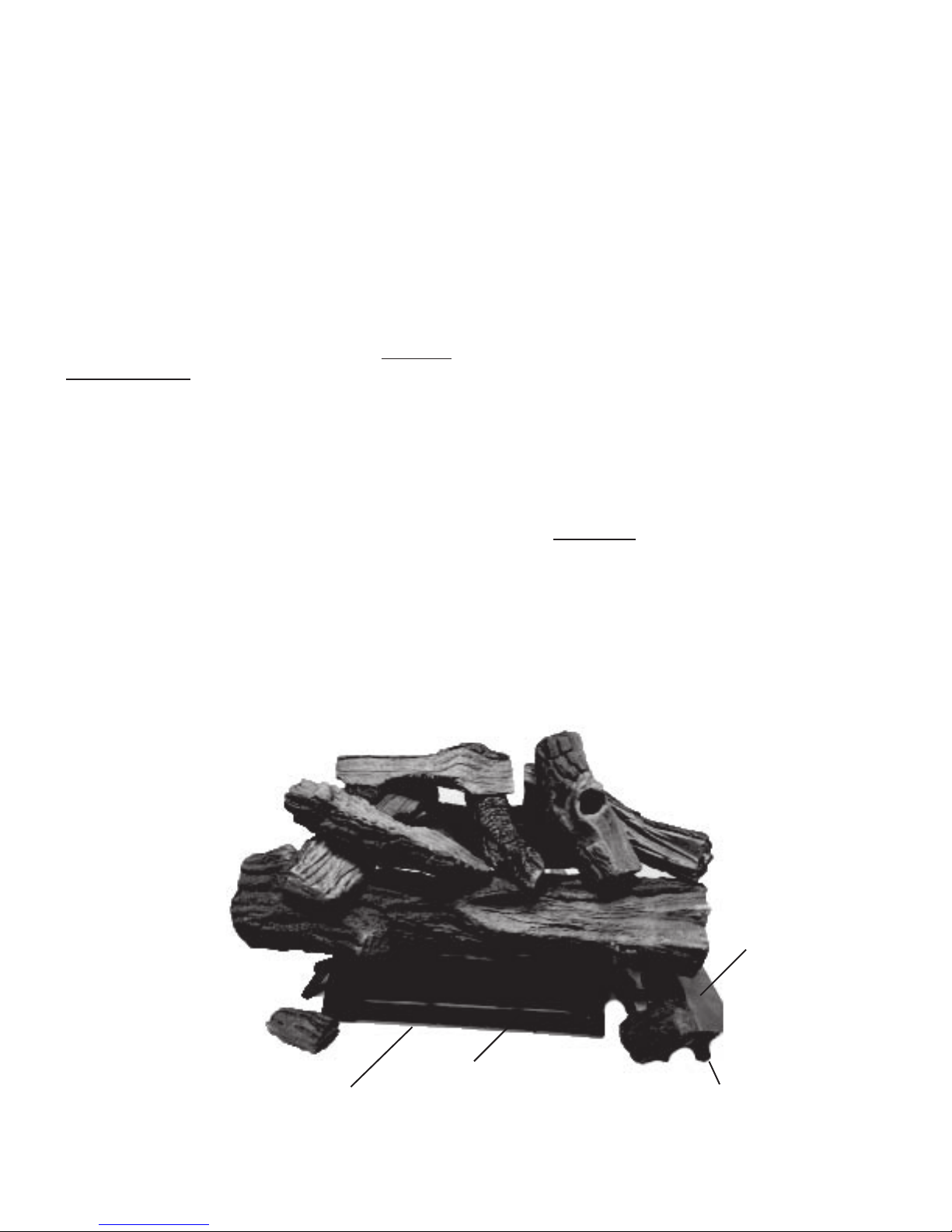
PRODUCT IDENTIFICATION
Burner Tube
Burner Pan
Figure 1 - Product Identification - VMO24RNGA Shown
Heat Shield
Control Knob
3
LOCAL CODES
Install and use log set with care. Follow all local
codes. In the absence of local codes, use the
latest edition of The National Fuel Gas Code ANSI-
Z223.1/NFPA 54*.
.
*Available from:
American National Standards Institute, Inc.
1430 Broadway
New York, NY 10018
National Fire Protection Association, Inc.
Batterymarch Park
Quincy, MA 02269
PRODUCT FEATURES
REMOTE CONTROL SAFETY VALVE/PILOT
This unit is provided with a remote gas control valve
which is connected to a wireless transmitter/receiver set, allowing safe operation from anywhere
in the room.
INSTALLATION
UNPACKING
CAUTION: Do not remove the metal data plates from the
burner pan. The data plates contain important warranty
and safety information.
1. Remove logs, hearth kit, pan materials,
and hardware from carton.
2. Remove all protective packaging applied
to logs and base for shipment.
3. Check appliance for any shipping damage.
If it is damaged call Sure Heat Manufacturing
at 1-800-229-5647 for replacement parts
before returning to dealer.
APPROVALS
Unit is tested and approved to ANSI Z21.60 as a vented
decorative appliance. It is supplied with the parts and instructions to convert to propane/LP gas use.
WARNING: The Massachusetts State
Board requires all installations be performed by a Licensed Plumber or Gas Fitter. Massachusetts state code requires all vent
dampers be welded open or removed.
CAUTION: Do not remove the data plates
attached to the burner pan. The data plates
contain important warranty and safety informat-
ion.
WARNING: Before installing in a solid fuel
burning fireplace, the chimney flue and firebox
must be cleaned of soot, creosote, ashes and
loose paint by a qualified chimney cleaner.
Creosote will ignite if highly heated. A dirty chim
ney flue may create and distribute soot within
the house. Inspect chimney flue for damage.
-
VENTING SPECIFICATIONS FOR
INSTALLATION
The fireplace chimney flue and vent must be drafting properly. To check the vent for proper drafting:
Light a tightly rolled newspaper on one end and
place it at the inside front edge of the fireplace.
Observe the smoke and be sure the vent is properly drawing it up the chimney. If the smoke spills
out into the room, extinguish the flame and remove
any obstruction until proper venting is achieved.
NOTICE: Installation, service, and repair of this appliance must
be performed by a qualified installer, service agency, company or gas supplier, experienced with this type of gas appliance. Only factory authorized components should be used,
in accordance with the manufacturer’s instructions and all
codes and requirements of the aut
Any modifications to this kit, or use of unauthorized components or accessory items will void the manufacturer’s warranty,
and may result in a hazardous condition.
hority having jurisdiction.
FLUE OPENING SPECIFICATIONS
Note: This vented appliance must be installed only in a
solid-fuel burning fireplace with a working flue and constructed of noncombustible material.
The chimney flue damper must be fixed open to provide a
minimum of 81 sq. in. of free air opening during operation
of this log set. A multipurpose damper clamp is provided
to fix the damper in position.
The minimum flue sizes shown in Figure 2 are based on
a 6' chimney height using round pipe. Your minimum flue
size will vary based on input rate and chimney height. Refer
to the National Fuel Gas Code ANSI Z223.1/NFPA 54,
Section 6.6, for details.
4
INSTALLATION
Continued
The charts in Figure 2 indicate technical information regarding the installation of your gas log set.
Please make sure that all of the specifications
shown are applicable before installation is attempted.
The fireplace must include a working flue and venting
system with the minimum openings shown in the
Figure 2.
MINIMUM FIREBOX SIZE
LOG
FRONT
SIZE
WIDTH
35
24"
DESCRIPTION
24" Dual Burner 60,000
BACK
WIDTH* DEPTH HEIGHT
3
/4"
17" 15
FUEL PRESSURE
SPECIFICATIONS (W.C.)
Inlet Manifold*
NG 5.5"-10.5" 3.5"
LP 11"-13" 10"
* ± .2"
1
Btu\Hr Input
Natural Gas
/2"
MINIMUM
FLUE SIZE
18"
Btu\Hr Input
Propane Gas
60,000
8" dia.
CHECK GAS TYPE
Use only natural gas. If your gas supply is not natural gas, you must convert the appliance to propane
/LP. Follow the instructions on page 7.
If the fireplace does not have a gas supply shutoff
valve, one must be installed.
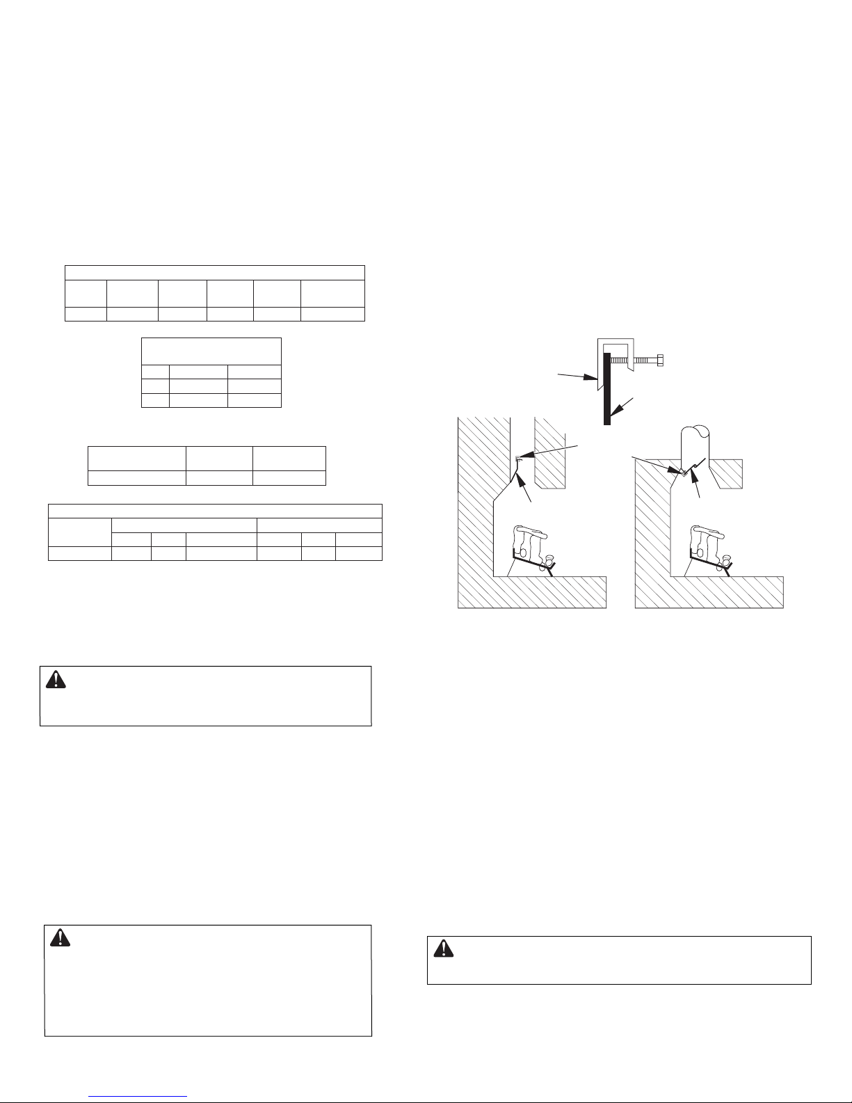
INSTALLING DAMPER CLAMP
Secure the damper stop clamp provided to the leading
edge of the damper as shown in Figure 3. If for any reason this clamp doesn't work on your fireplace, another
suitable clamp or permanent stop must be installed, or
the damper blade must be cut or removed.
Damper
Clamp
Damper
Damper
Clamp
BURNER ORIFICE
LOG
SIZE
24” .144 #27 .089” #43
NATURAL PROPANE/LP
In. Num. In.
Num.
Figure 2 - Technical Information Charts
CONNECTING TO GAS SUPPLY
WARNING: A qualified service person must
connect log set to gas supply. Follow all
local codes.
Installation Items Needed
Before installing log set, make sure you have
the items listed below.
• piping (check local codes)
• sealant (resistant to propane/LP gas)
• equipment shutoff valve
• adjustable (crescent) wrench or pliers
• sediment trap
• tee joint
• pipe wrench
Damper
-
Damper
Manufactured FireplaceMasonry Fireplace
Figure 3 - Attaching Damper Clamp
CONNECTING TO GAS SUPPLY
Continued
Installation must include an equipment shutoff valve with
"T" style handle, gas union and, for propane/LP gas only,
a plugged 1/8" NPT pressure tap. Locate NPT tap within
reach for test gauge hook up. NPT tap must be upstream
from log appliance
(see Figure 4).
IMPORTANT: Install equipment shutoff valve in an accessible location. The equipment shutoff valve is for
turning on or shutting off the gas to the appliance.
Apply pipe joint sealant lightly to male NPT threads. This
will prevent excess sealant from going into pipe. Excess
sealant in pipe could result in a clogged burner injector.
CAUTION: Use only new, black iron or
steel pipe. Internally-tinned copper tubing may
be used in certain areas. Check your local
codes. Use pipe of 1/2" diameter or greater to
allow proper gas volume to log set. If pipe is too
small, undue loss of
volume will occur.
WARNING: Use pipe joint sealant that is resistant
to liquid petroleum (LP) gas.
5

INSTALLATION
Continued
We recommend that you install a sediment trap in
the supply line as shown in Figure 4. Locate sediment
trap where it is within reach for cleaning.Install in piping
system between fuel supply and heater. Locate sediment trap where trapped matter is not likely to
freeze. A sediment trap traps moisture and contaminants. This keeps them from going into log set controls.
If sediment trap is not installed or is installed wrong,
log set may not run properly.
CSA Design-Certified
Equipment Shutoff Valve
With 1/8" NPT Tap*
4. Check all joints of gas supply piping system.
Apply a noncorrosive leak detection fluid to all
joints. Bubbles forming show a leak.
5. Correct all leaks at once.
6. Reconnect log set and equipment shutoff valve
to gas supply. Check reconnected fittings for
leaks.
Test Pressures Equal To or Less Than 1/2
PSIG (3.5 kPa)
1. Close equipment shutoff valve (see
Figure 5).
From Gas
Approved Flexible
Gas Hose (no longer
than 36" if required by
local codes)
Meter (5"
W.C.** to
10.5" W.C.
Pressure)
3" Minimum
Tee Pipe Cap
Joint Nipple
Sediment Trap
Figure 4 - Gas Connection
* Purchase the optional CSA design-certified equipment
shutoff valve from your dealer. **Minimum inletpressure
forpurpose ofinput adjustment.
CHECKING GAS CONNECTIONS
WARNING:Test allgas piping and connections, internal and external to unit, for leaks after installing
or servicing. Correct all leaks at once.
WARNING: Never use an open flame to check
for a leak. Applyanoncorrosiveleakdetection fluid to
all joints. Bubbles forming showa leak. Correct all
leaks at once.
PRESSURE TESTING GAS SUPPLY PIPING
SYSTEM
Test Pressures In Excess Of 1/2 PSIG (3.5 kPa)
1. Disconnect logset anditsindividual equipmentshutoffvalve from gas supply piping system.
2. Cap offopen endofgas pipewhereequipment shutoff valve was connected.
3. Pressurize supply piping systembyeither using compressed airor openingmain gas valve located on or
near gas meter.
-
-
2. Pressurize supply piping systembyeither using
compressedair oropening maingas valve located on or near gas meter.
3. Check all joints from gas meter to equip ment
shutoff valve (see Figure 5). Apply a noncorrosive leak detection fluid to all joints. Bubbles
forming show a leak.
4. Correct all leaks at once.
Equipment
Shutoff Valve
Gas Meter
Figure 5 - Checking Gas Joints
HEARTH PAN INSTALLATION
If using propane/LP gas, see Propane/LP
Gas Conversion page 7 before installing
hearth pan.
1. Place the burner pan assembly in the center
of the fireplace floor. Make sure the front of
pan faces forward.
2. Thread the gas supply fitting to the fire place
gas supply pipe. Adjust to most convenient
position.
3. Install the gas connector tube to the gas supply
adapter.Carefully shape tube and attach to gas
inlet fitting (see Figure 6). Be careful not to
cause kinks in tube.
4. Test for leaks following instructions under
Testing Burner for Leaks , page 8.
6
 Loading...