

Page 1
Replacement Parts
List
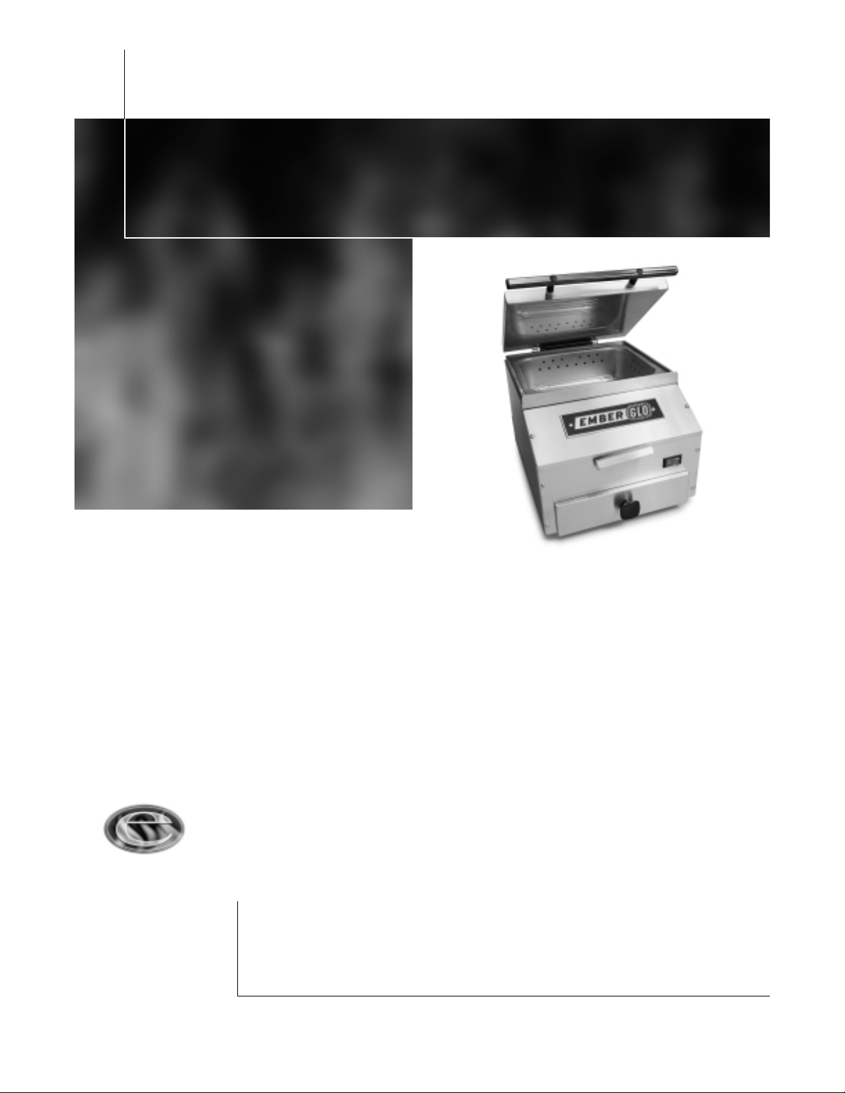
EmberGlo Model ES5M
Designed to Operate W ithout
Distilled Water
EmberGlo
A Division of Midco International Inc.
4140 West Victoria Street
Chicago, Illinois 60646
tel 773.604.8700
fax 773.604.4070
web www.emberglo.com
EmberGlo
Quality Designed for Proven Performance
Manual Operation Steamer
with Water Pan
PRINTED IN U.S.A.
299
8472-50
Items listed are replacement parts for the current Model ES5M Tap Water Steamer and its
components.
Model ES5M first construction May, 1983.
■■
■■ Original construction featured a non-counter balanced 90° opening lid. Steamers built
after January 29, 1990 (date code 0590) feature a counter balanced adjustable 60° or
90° opening lid.
■■
■■ Original patterns for early Sand Cast Aluminum Generators replaced by Semi
Permanent Molds August 27, 1992 (date code 3592). Refer to page 3, Generators.
AVOID ERROR IN PARTS SELECTION. When ordering use complete Ember•Glo part number
and description; furnish steamer model number, date code, bill of material number, serial
number and component nameplate data where available.
Page 2
2
Page 3

3
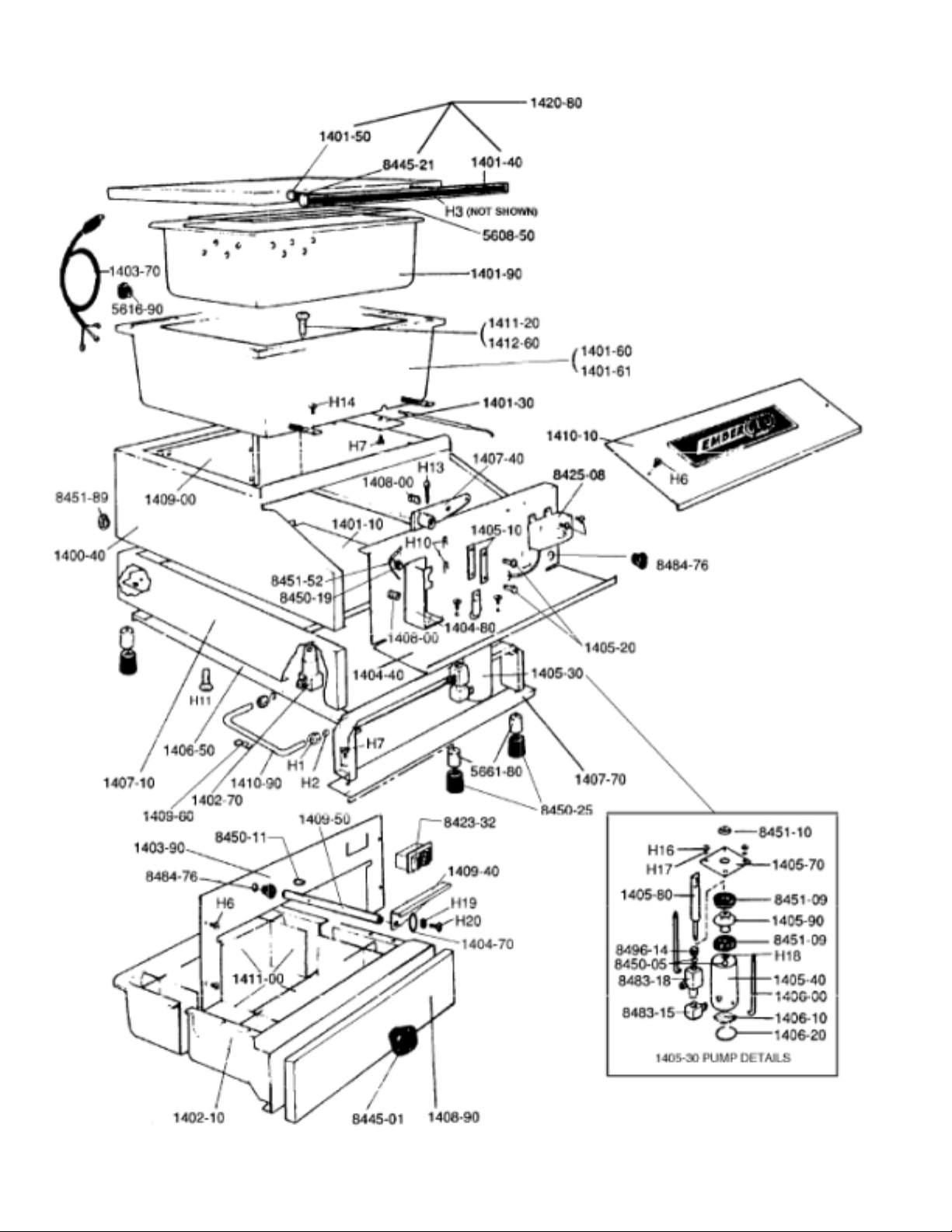
PART NUMBER DESCRIPTION
1400-20 Pump Handle Weldment
1400-40 Shell Weldment
1401-10 Rear Bottom
1401-30 Bulb Clamp
1401-60
1
Generator (120 volt)
1401-61
1
Generator (220 volt)
1401-90 Food Pan
1402-10 Water Pan Rivetment
1402-70 Water Inlet
1403-70 Power Cord (3 Prong, 120 volt)
1403-90 Switch Panel
1404-40 Front Bottom Panel
1404-70 Pump Handle Washer
1404-80 Pump Handle Support
1405-10 Pump Link (2-required)
1405-20 Pump Pin (2-required)
1405-30 Pump Assembly
1405-40 Pump Cylinder Assembly
1405-70 Pump Cylinder Mounting Plate
1405-80 Pump Piston Rod
1405-90 Pump Piston
1406-00 Pump Tie Rod (2-required)
1406-10 Pump Strainer
1406-20 Pump Retainer
1406-50 Water Pan Slide Weldment
1407-10 Water Pan Shell Weldment
1407-40 Pump Crank Assembly
1407-70 Leg Channel
1408-00 Spring Seat (2-required)
1408-90 Water Pan Front
1409-00 Stiffener
1409-60 Water Tube Clip (2 required)
1410-10 Control Box Cover and Nameplate Assembly
1410-90 Water Tube and Fittings
1411-00 Water Pan Baffle Set
1411-20 Water Nozzle with Spring
1412-60 Water Nozzle Spring only
1420-00 Hinge Spring Bar (2 required)
1420-40 Hinge Spring (2 required)
1420-80 Lid Assembly (Lid and Handle)
1421-00 Adjustable Lower Hinge
1421-50 Hinge Lid Stop Rivetment
1421-60 Adjustable Upper Hinge
1435-00 Lid Handle Replacement Kit
5608-50 Food Grid
5616-90 Strain Relief (SR-6P-4)
1. Refer to Generators below
PART NUMBER DESCRIPTION
5661-80 Aluminum Leg (4 required)
8423-14 On-Off Rocker Switch
8425-08 Thermostat
8432-08
5
/16" OD x 3/16" ID O-Ring (2 required)
8445-01 Water Pan Knob
8450-05
9
/32" Dia. Stainless Steel Ball (2 required)
8450-11 Woodruff Key
8450-19
3
/8Nyliner
8450-25 Socket Tip (4 required)
8451-09 Pump Cup (2 required)
8451-10
5
/16Nyliner
8451-52 Pump Spring
8451-89
9
/16" Dia. Plug Button
8483-15
1
/8Brass Street Ell
8483-18
1
/8Brass Adapter Tee
8484-76 Snap Bushing (B-500-375)
8496-14
1
/8" Slotted Brass Pipe Plug
The Following Are Not Shown
1410-50 Insulation Kit (Sides, Back, Front & Bottom)
1410-60 Electrical Wire Kit (less power cord)
1419-00 Adjustable Hinge Retrofit Kit and Hardware
1446-00 Thermostat Disc to Bulb Kit
PART NUMBER HARDWARE (obtain locally)
H1
1
/4Tube Compression Nut
H2
1
/4Tube Compression Sleeve
H3 10-32 x 2 Round Head Machine Screw
H4 10-32 x
3
/8Truss Head Machine Screw
H5
H6 8 x
3
/8Truss Head Type "B"
H7 10-24 x
3
/8Round Head Machine Screw
H8 6 x
1
/4Pan Head Type "AB"
H9 #10 Stainless Steel Lockwasher
H10 Hitch Pin
H11
1
/4-20 x 2 Round Head Machine Screw
H12
H13
1
/8x 1 Cotter Pin
H14 8-32 x
5
/16Pan Head Machine Screw
H15
H16 6-32 Hex Brass Nut
H17 #6 Stainless Steel Lockwasher
H18 10-32 Hex Brass Nut
GENERA TORS
Original patterns for Sand Cast Aluminum generators replaced by Semi Permanent Molds August 27, 1992 (Date Code 3592).
Generators from Semi Permanent Molds feature vertical ribs on each wall of Generator cavity. These ribs inhibit the food pan
from nesting against any wall. When replacing an early (without ribs) Generator, the two bolt holes in the REAR BOTTOM panel
must be filed to accommodate the new Generator. The distance between centers on the two 1/4-20 mounting bosses has been
reduced
1
/4inch (was 121/2" now 121/4"). If this is not acceptable, order 1401-10 REAR BOTTOM panel when ordering a
replacement Generator.
Note: Replacing the REAR BOTTOM panel is labor intensive. We recommend filing the existing REAR BOTTOM panel.
Page 4

ADJUSTABLE HINGE FOR 2-POSITION LID OPENING
(60° OR 90° OPEN)
First construction January 29, 1990 (date code 0590). Steamers built before this date featured a 90° opening lid. Replacement
parts for the early construction are no longer available. When replacing any parts on the early design or if converting to 2position lid opening, order Part Number 1419-00 ADJUSTABLE HINGE RETROFIT KIT.
TO REMOVE LID OR CHANGE OPENING
Remove lid stop rivetment by sliding it up and away from steamer. Raise lid as far back as it will go, remove springs. Remove lid.
Inverting lid stop rivetment changes lid opening from 60° to 90° or from 90° to 60°.
TO RESET LID
Remove lid stop rivetment and springs. Loosen four 10-32 x 3/8Phillips truss head screws in lower hinge. Place a coin under lid
and on top of generator rim at both rear corners. Hold lid down along front edge. Tighten screws. Reinstall springs and lid stop
rivetment.
4
 Loading...