

Page 1
Installation Service
Manual & Parts
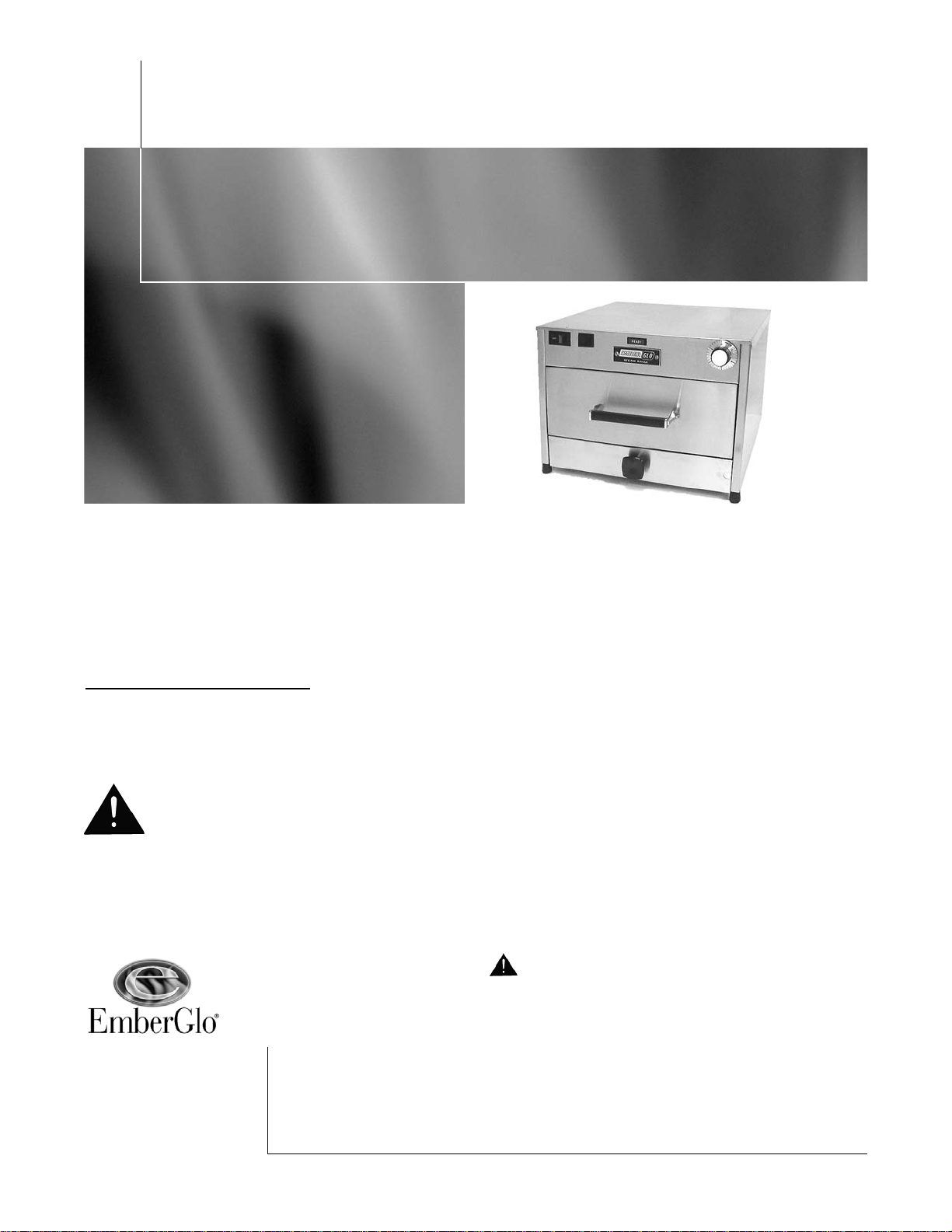
EmberGlo Model AR60T
EmberGlo
A Division of Midco International Inc.
4140 West Victoria Street
Chicago, Illinois 60646
tel 773.604.8700
fax 773.604.4070
web www.emberglo.com
e-mail sales@emberglo.com
Quality Designed for Proven Performance
PRINTED IN U.S.A.
101
8471-13
CAUTION:
This steamer to be used with distilled water only
(demineralized). Without treated water, deposits can build
up in steam generators causing reduced steam volume and
eventual stoppage of steam production. Clogged or limed
steam generators caused by use of non-distilled water will
not be covered under the terms of the warranty.
Warranty
All electrical equipment sold under the Ember-Glo trademark
is warranted against defects in material and workmanship for
a period of one year from date of original installation. Midco's
obligation under this warranty shall be limited to repairing or
replacing, at our option, any part of said equipment which
Midco's examination shall disclose to its satisfaction to be
thus defective.
Under the terms of this warranty , models considered portable
(devices with cords and plug caps such as Midco Steamers)
must be returned to the nearest service station,
transportation prepaid. Non-portable units with permanent
wiring will be serviced on the customer's premises. Under
these terms, Midco agrees within the terms of this Warranty,
to make all repairs at no charge. Portable units will be
returned, transportation collect.
This warranty does not apply to damages resulting from
accident, misuse, abuse or alteration.
No equipment may be returned without written authorization
from Midco. Returned goods must be shipped prepaid to the
factory.
WARNING: Improper installation and use of this
product could result in personal or property injury.
Warranty card must be filled in and returned to Midco to
validate warranty.
SAFETY INFORMATION TTERMS:
The following terms are used to identify hazards, safety
precautions or special notations and have standard
meanings throughout this manual. When you see the safety
alert symbol and one of the safety information terms, as
shown below, be aware of the hazard potential.
DANGER: Identifies the most serious hazards
which will result in sever personal injury or death.
WARNING: Signifies hazards that could result in
personal injury or death.
CAUTION: Identifies unsafe practices which
would result in minor personal injury or product
and property damage.
Specifications:
- 120 volts 60HZ AC 1500 watts 12.5 amp
- Automatic timer operation
- Single shot operation
- End of cycle buzzer (10 seconds)
Page 2

Installation
Operation
Maintenance
Daily
Service
1. Position steamer on level surface and plug power cord into 3-hole 120 volt AC
grounded receptacle. If an adapter is used, it must be grounded properly.
2. Pull out water pan and fill with distilled (NOT HOT OR BOILING) water to
1
/4" from the
top of the water pan baffles; then close drawer. Unit is now ready for operation.
1. Move rocker switch to ON position. The ready light will come on but you must allow 15-20
minutes to reach operating temperature.
2. Open food drawer, place food in pan; close drawer and turn dial of timer to time
required per cooking guide. Depress push button at center of timer (ready light will go
out) and cycle will proceed. When the cycle has completed, ready light will come on
and buzzer will sound for 10 seconds. At the end of the cycle open drawer and
remove food.
3. Manual Operation: Depress square switch approximately 1 - 2 seconds.
The food pan is removed by lifting up. Clean the inside thoroughly and wipe the outside to
remove any material which might have accumulated.
To remove the food drawer, pull the drawer out until it stops, release stop located at rear
underside of drawer to unlock, and pull out the frame. Wipe the drawer and frame clean and
return by inserting the drawer slide into the slide of the frame, then push the food pan to the rear
until the lock engages automatically.
DANGER: READ AND UNDERSTAND THIS BULLETIN THOROUGHLY BEFORE
STARTING ANY TROUBLE SHOOTING. AN INADVERTENT SERVICE ERROR COULD
RESULT IN SEVERE PERSONAL INJURY OR DEATH. ONLY A TRAINED EXPERIENCED
SERVICE TECHNICIAN SHOULD ATTEMPT ANY REPAIR PROCEDURE.
Qualified serviced agencies are available at most locations - Refer to EmberGlo listing of
AUTHORIZED SERVICE AGENCIES included in Standard Equipment Catalog.
Note: Before attempting service, unplug power cord. For service or examination, all "working
parts" of the steamer are exposed by removing first the cabinet top, then the back. The wiring
diagram and spare clean out gasket is located on inside of back.
Electric Switch/Thermostat
The on-off switch should audibly "click" when operated manually. To determine if electrically
operative, a continuity check should be made.
The thermostat is factory calibrated and non-adjustable and should not be repaired. Replace if
defective.
Pump System
The pump system is an electrical vibrator type which is controlled by the main timer. It supplies
power to the solid state (#606) recycle timer. A failure in this circuit may be traced from the main
timer thru the solid state timer. Please note that the "on" time of the solid state timer may be as
short as .1 second and then 10 seconds "off" . See the schematic for test points. If the pump is
operating but not pumping, check that the filter mounted on the inlet side of pump is not clogged,
if so, remove and clean. If still not streaming, refer to the “Steam Generator” section of this
manual.
Installation and Service
2
Page 3
Service
Continued
Timers
There are three timers in this system.
1. Push-button Automatic Reset - times length of cycle in minutes and supplies power to the
solid state timers. To determine if timer is functioning properly a volt meter or test lamp may
be used. See schematic for test points.
2. Solid State Programmable Recycle #606 - times length of shot (.1 second adjustable) and
time between shots (10 seconds adjustable). To determine if timer is functioning properly, a
volt meter or test lamp may be used. See schematic for test points.
3. Solid state delay interval programmable timer - 6013 - buzzer item delay and buzzer on time.
Factory set at .1 second delay and 10.0 second on time. To determine if timer is functioning
properly, a volt ohmmeter or test lamp may be used. See schematic for test points.
Dip Tube and Spring
If the dip tube does not enter the water pan properly it must be replaced. When replacing, the
open end or point of hook must be at the bottom and the eye must be in a vertical plane, like a
coin standing on edge.
Steam Generator
1. To Clean. Remove cabinet top and generator insulation. This will expose a square plate on
the generator, which is removable for cleaning water passages.
Check the three exposed holes when the clean-out cover is removed. If any of these
holes are clogged, clean them out by hand-twisting a
7
/ 64" drill for the center hole and a
3
/16" drill for the two side holes.
After thoroughly cleaning the three holes, plug in power supply and operate momentary
switch to steam unit. THE UNIT MUST BE HOT. Operate several times to blow out any
accumulation.
Replace the clean out cover, using new gasket. With the unit hot, operate pump with the
momentary switch. The unit should steam properly. If it does not, and the pump is operative
as detailed under PUMP SYSTEM, the entire generator assembly is probably limed and must
be disassembled and cleaned or replaced.
To clean generator assembly, separate casting from plate and clean lime from cavity in
casting.
Caution: Do not damage plate by scratching or polishing the finish.
2. To Remove.
Disconnect the water riser tube.
Disconnect electric wiring at the two terminals.
Remove 16 hex nuts. Note: Remove food drawer and hold screws up to prevent turning.
Separate generator from discharge plate.
3
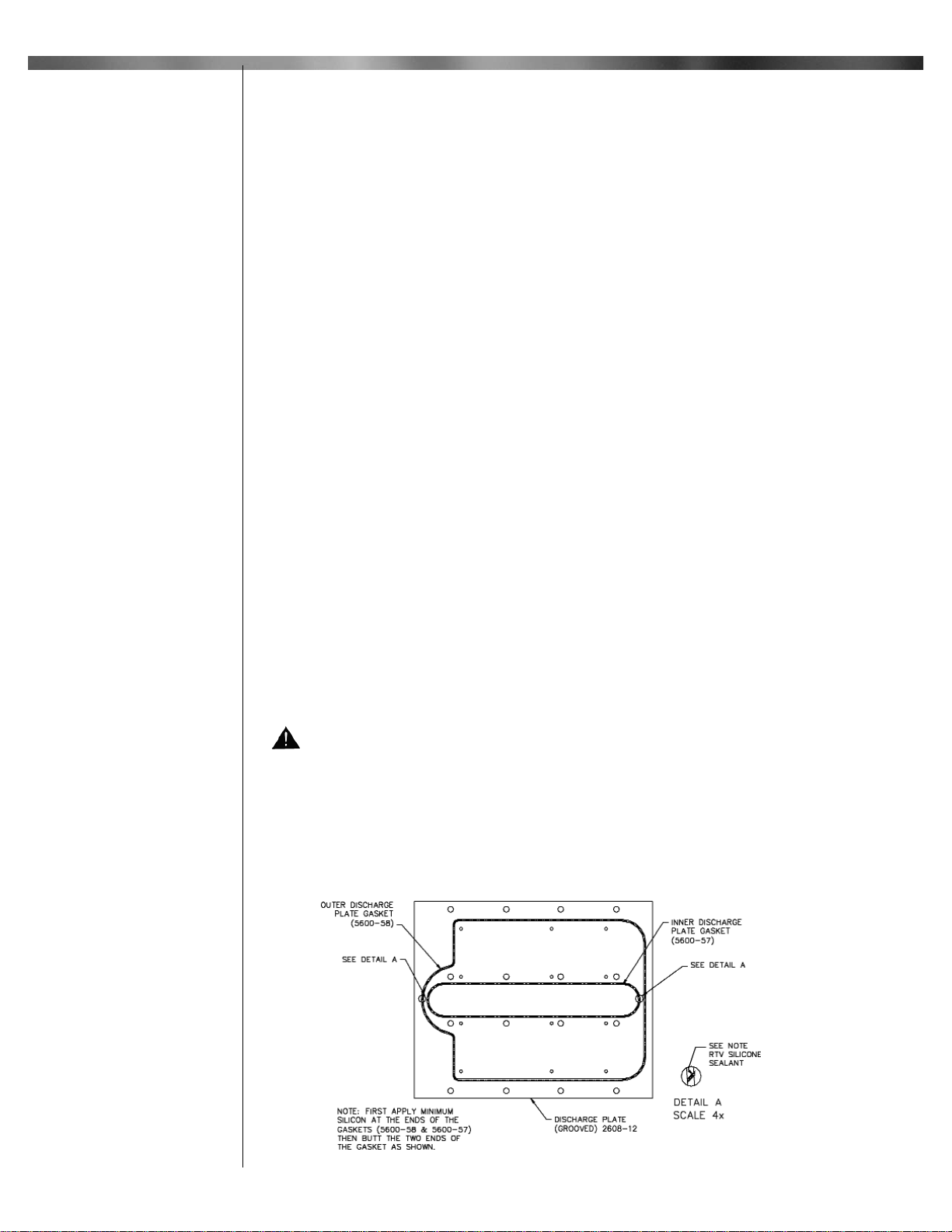
Figure 1. Generator Casting
Page 4

1. Unit will not heat up; light out.
a. No power.
b. Plug out.
c. Loose internal connection.
d. Defective switch.
2. Unit will not heat up; light on.
a. Defective thermostat.
b. Loose heating element connection.
c. Defective generator heater.
3. Unit heats up light will not light.
a. Defective light in switch.
b. Loose connection.
4. Unit heats up; does not steam.
a. No water in pan.
b. Defective pump.
c. Leak in inlet tube.
d. Dip tube spring assembly misaligned.
e. Clogged steam generator, or strainer.
f. Defective solid state timer.
g. Defective cycle timer.
Note: If electrical trouble is other than loose connections, it is recommended that parts be
replaced rather than repaired.
Trouble
Chart
4
Remove the old gaskets from the discharge plate and scrape residue silicon from the discharge
plate. Clean the groove of the discharge plate. To install the new gaskets in the discharge plate
grooves, as shown in Figure 1, first apply a bead of Dow Corning 732 or General Electric 159 RTV
silicon adhesive at the ends of the gasket then butt the two ends of the individual gasket. Place
discharge plate and silicon assembly on the steamer (gasket facing towards generator) so that
steam holes line up with the twelve round holes in steam chamber. Place the generator on the
above assembly so that mounting holes line up with the sixteen round holes in the discharge
plate. Tape the carriage bolts in place from inside steam chamber and then tighten the nuts with
lock washers. Remove all tape.
3. To Replace. Remove the old gaskets from the discharge plate and scrape residue silicon
from the discharge plate. Clean the groove of the discharge plate. To install the new gaskets in
the discharge plate grooves, as shown in Figure 1, first apply a bead of Dow Corning 732 or
General Electric 159 RTV silicon adhesive at the ends of the gasket then butt the two ends of the
individual gasket. Place discharge plate and silicon assembly on the steamer (gasket facing
towards generator) so that steam holes line up with the twelve round holes in steam chamber.
Place the generator on the above assembly so that mounting holes line up with the sixteen round
holes in the discharge plate. Tape the carriage bolts in place from inside steam chamber and
then tighten the nuts with lock washers. Remove all tape. Place casting on plate carefully so that
holes align properly. Replace screws and tighten securely. Allow the RTV to set approximately
24 hours before operating unit.
Page 5

Heating and Cooking Guide
These suggestions are made only to help the operator get started. Since each location will
have different portions and different requirements, each operator must determine his own
operation habits. Please remember that the steamer conserves its steam in the drawer and
therefore does not often need repeated shots. The main exception is when frozen product
must be defrosted.
If a product is at room temperature or refrigerated, start with 2 shots. This ensures that
the food pan is full of steam.
If a product is frozen, start with 3 shots because condensation on the cold product
eliminates the steam quickly.
Cooking Instructions
Meats
Sliced meats
Hamburger patties (precooked)
Cheeseburger (precooked)
patty with cheese
patty with cheese on bottom bun
Hot Dogs
Bacon (precooked)
Link Sausage (precooked)
1
/
2
Chicken (1lb)
Ribs (precooked)
Poached
Soft Boiled
Buns (open)
Buns (closed)
Rolls
Macaroni and Cheese (casserole)
Rice (precooked)
Spaghetti (precooked)
Vegetables (precooked)
Chop Suey (casserole)
Shrimp (unfrozen)
2
2
2
2
2
2
2
2
2
1
2
2
3
2
2
2
3
3
10-20
30
30
90
60-90
45
60
60
30
10
20
20
90-120
45-60
45-60
30-45
90-120
90
Shots Seconds
Eggs
Bread
Pasta
2 shots/60 sec. then
2 shots/30 sec.
2 shots/60 sec. then
2 shots/90 sec.
Excellent results can also be achieved with many other precooked or frozen foods such as
any non-breaded seafood… clams… lobster tails… scallops… red snapper… crab legs…
all breads and rolls… french bread loaves… hoagies… onion buns… many specialty
foods… tortillas… enchiladas… pizza slices… and much more!
5
Page 6

Parts
Avoid error in parts selection. When ordering, use complete Ember-Glo part number and description. Furnish model
number, bill of material number and date code or serial number from specification plate.
IMPORTANT: Availability of parts as well as specifications are subject to change without notice.
Please consult factory for item availability.
6
Item # Part # Description Qty
1 5600-22 Steam Chamber Weldment 1
2 5600-41 Left Cabine t Side 1
3 2608-12 Discharge Plate grooved 1
4 5655-00 120V Generator 1
5 5600-46 Bulb Clamp 1
6 5602-20 Clean Out Cover Gasket 1
7 5601-90 Clean Out Cover 1
8 8496-11 1/8 Brass Plug 1
9 5600-43 Upper Switch Panel 1
10 8423-14 On-Off Rocker Switch 1
11 8423-36 Push Button Switch 1
12 5601-40 Generator Insulation 1
13 5600-44 Cabinet Top 1
14 8408-66 Pil-Light Ready 120v 1
15 5677-50 Water Pan Blank 1
16 5682-50 Food Pan Grid 1
17 8445-04 Black Vinyl Grip Handle 1
18 5678-00 Food Door 1
19 5687-00 Door Linear/Gusset Weldment 1
20 5663-90 Food Drawer Nut Plate 2
21 5686-50 Food Drawer Rivetment 1
22 5682-00 Slide Channel Rivetment 1
23 5663-10 Slide Channel Stop 1
24 5622-00 Steam Range Nameplate 1
25 8406-71 Timer 5 Min 120/1/60 1
26 5600-42 Right Cabinet Side 1
27 5600-35 Shaft Extender 1
28 5600-34 Push Rod 1
29 5600-53 Retainer 1
30 5600-36 Collar 1
31 5600-27 Switch Mounting Bracket 1
32 5661-71 Right Water Pan Support 1
33 5691-00 Steam Chamber Bottom Rivetment 1
34 1425-00 Buzzer Assy 120V 1
35 8445-01 Water pan knob 1
36 5600-23 Latch Slide 1
37 5600-50 Latch Spring 1
38 5600-48 Latch Base 1
39 5600-30 Water Pan Weldment 1
40 5686-00 Water Pan Baffle 2
41 5661-80 Aluminum Leg 2
Item # Part # Description Qty
42 8450-25 Socket Tip 4
43 5600-28 Rear Leg Extension 1
44 8406-66 Delay Interval Timer Mod 6013 1
45 8406-70 Recycle Timer Mod 606 2
46 8425-08 Robershaw Thermostat 1
47 5604-30 Dip Tube Spring Assembly 1
48 5600-56 Dip Tube Assembly 1
49 1418-00 Pump Clamp 2
50 8451-74 Strainer (inside) 1
51 1423-01 Food Steamer Pump 1
52 5600-64 Tubing Assembly AR60T 1
53 5600-37 Drain Cup Assembly 1
54 5600-45 Cabinet Back (Back Panel) 1
55 5661-70 Right Water Pan Support 3"
56 8483-00 1/8M x 1/4T Compression El 1
57 5600-47 Power Cord Assembly 14"
H1 8451-36 #10-24x1-1/2 S.S Carriage Bolt 16
H2 #10 Flat Washer Zinc Plated 16
H3 #10-24 Hex Nut Zinc Plated 23
H4 #10-24x3/8 Slotted Round Head S.S 16
H5 #10 Split Lockwasher S.S 16
H6 #6-32x1 Slotted Oval Head Nickel Plated 2
H7 #6 Split Lockwasher S.S 2
H8 #6-32 Hex Nut Zinc Plated 2
H9 #8-32x3/8 Phillips Round Washer Head 14
H10 10-24x7/8 Slotted Round Head S.S 2
H11 10-32x3/8 Phillips Truss Head S.S 4
H12 10-24x1/4 Slotted Pan Head S.S 1
H13 10-24x1/4 Cup Point Set Screw 1
H14 10-24x1/4 Phillips Head S.S. 1
H15 5/16 Spring Clamp 3
H16 #8-32x1-1/4 Self-tap PHMS 2
H17 #6-32x1/8 Slotted Round Head Zinc Plated 6
H18 #8-32x5/16 Thumb screw 1
H19 #8 Large OD 11/64" ID x 3/4" OD 1
H20 #8-32 Hex Screw S.S. 3
H21 #8-32x3/8 Phillips Round Head S.S. 2
H22 #8-32x3/8 Phillips Round Head S.S. 2
Page 7

Exploded View
7
Page 8

EmberGlo A division of Midco International Inc. 4140 West Victoria Street * Chicago, Illinois 60646
tel 773.604.8700 fax 773.604.4070 web www.emberglo.com email sales@emberglo.com
101
8471 13
Printed in USA
 Loading...