

Troubleshooting
Guide
EmberGlo Model AR60
EmberGlo
A Division of Midco International Inc.
4140 West Victoria Street
Chicago, Illinois 60646
tel 773.604.8700
fax 773.604.4070
web www.emberglo.com
Quality Designed for Proven Performance
WARNING:
Unplug power supply cord before removing top
and back. Procedures described in this booklet are
to be done with unit disconnected from power source.
PRINTED IN U.S.A.
1098
8471-08

Operation overview
Operational guidelines 1
Problems
Unit will not heat up and light is out 1
Unit will not heat up and light is on 1
Unit heats up but does not steam—
water system problem 2
Unit Heats up but does not steam—
generator problem 3 & 4
Unit steams but food is wet or soggy 4
Unit steams but very slowly 4
Schematic drawings
AR60 Internal Wiring 4
AR60 Exploded View 5
Replacement parts
AR60 Parts and Hardware List 6
Contents
EmberGlo Model AR60
Operational Guidelines
For maximum performance of Model AR60 the following
recommendations should be followed.
1. Use distilled water only.
Most areas of the country require use of room temperature
distilled water otherwise the generator will become clogged
with mineral deposits. Do not use cleaners, de-limers or other
chemicals in the steamer.
2. Keep water pan clean.
Food particles and debris will restrict or stop the amount of
water reaching the generator. A strainer inside pump inlet tube
will collect any foreign matter and should be checked periodically
to see if water supply is being kept clean.
3. Allow steamer to heat up for 20 minutes before using.
This helps reduce condensate and poor performance.
4. Keep drawer closed when not in use.
This keeps the food pan hot and reduces condensation in the
steam chamber.
5. Avoid over-pumping.
The steamer is designed to steam once every 20 seconds.
Constant pumping more frequently than this will reduce
the performance or even cause generator flooding.
1
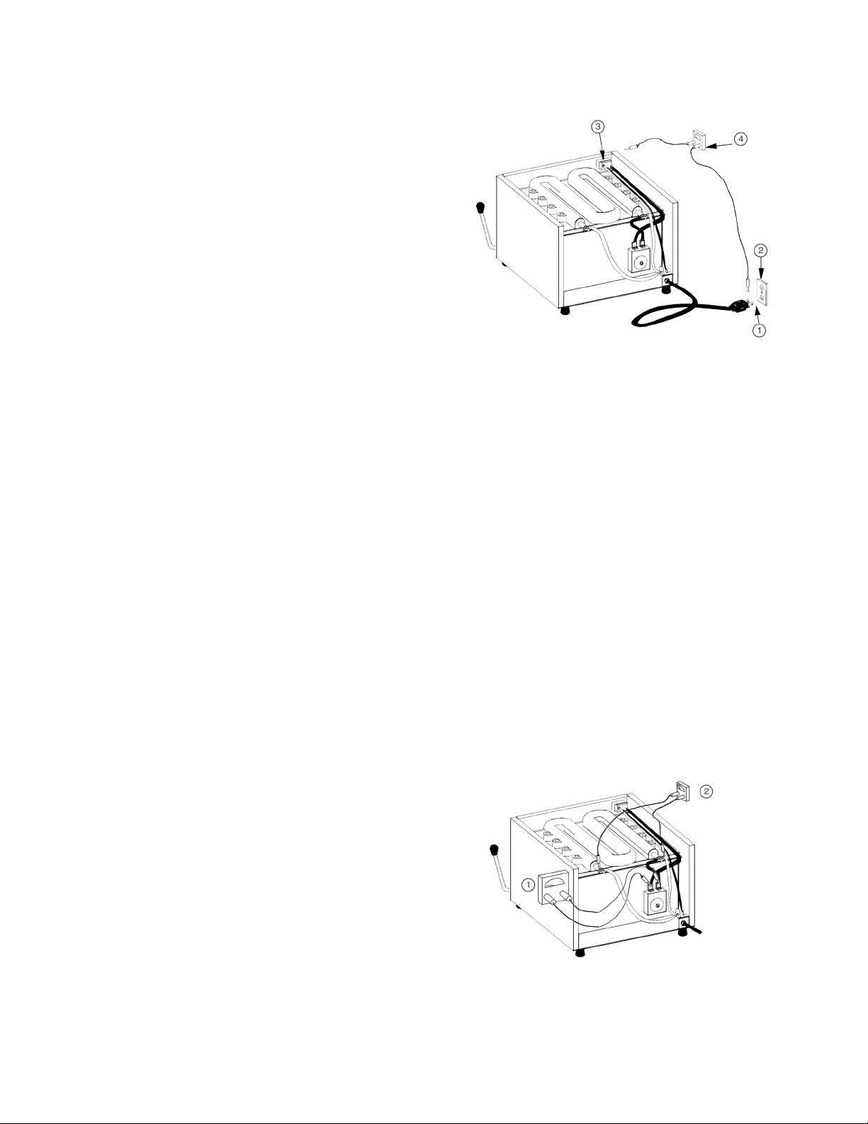
Unit Will Not Heat Up and Light Is Out
(See Figure 1)
1. Unit is unplugged.
Plug unit in.
2. No power to outlet.
Check voltage at outlet. It should be 115-120 volts.
If there is no voltage, then problem is in building circuit.
3. Defective switch.
Check continuity through switch. If there is no continuity,
then replace switch.
4. Loose or broken wire.
Check continuity from cord plug to switch, from switch to
thermostat, from thermostat to element, from element back
to plug. Tighten loose screws or replace defective cord or wire.
Be sure white (neutral) is connected to non-switched terminal
of power switch.
Figure 1
Unit Will Not Heat Up and Light Is On
1. Defective thermostat.
Check continuity across thermostat when unit is off and at room
temperature. If there is no continuity, then replace thermostat.
Thermostat is normally closed and opens at 350°F. Thermostat is not
repairable.
2. Defective generator element.
Check continuity at element terminals. An ohmmeter check
across element terminals should read about 10 Ω. If no continuity,
then replace generator.
3. Loose or broken wire.
Check continuity between switch and thermostat and thermostat
and element. Tighten screws or replace open wire.
(See Figure 2).
Figure 2

2
Unit Heats Up But Does Not Steam—
Water System Problem
1. No water in pan or water below inlet tube.
Fill water pan to about 1/4" of top of water pan baffles. The water
pan will comfortably hold about 3
1
/4quarts of water. This is enough
water to operate the steamer constantly at maximum capacity for
about two hours.
(See Figure 3).
Figure 3
Figure 5
Figure 4
2
4
3
2. Crank or linkage defective or disengaged.
(See Figure 4).
Remove top and rear panels, then operate pump handle and observe
pump shaft at rear of unit. Pump shaft should move about
7
/8" as
handle is depressed. Spring should return handle to upright position.
Replace defective or worn parts
or reconnect disengaged parts.
3. Clogged pump strainer.
Loosen inlet check nut and remove strainer. Clean strainer
and reassemble.
4. Leak in pump tube assembly.
Remove pump tube assembly and look for cracks or holes in plastic
tube. Replace if defective.
(Note: The open end of dip tube spring hook must be at
bottom of water pan.)
5. Defective pump.
(See Figure 5)
The pump is constructed with ball and spring check valves.
The valves may be inspected by removing pump from machine
and then disassembling valves. Look for broken springs, damaged
balls and damaged or worn seats. Sometimes just a tiny particle
on the ball seat can cause problems. Clean seats, replace defective
parts and reassemble.
(Note: Do not over tighten fittings. They should be just tight
enough to prevent leaking.)
• Test by assembling pump tube assembly to pump and immersing
end of plastic tube in water. Pull pump shaft out. Push pump shaft in
and a stream of water should shoot out of outlet fitting several feet.
Try pump several times in this manner to make sure it performs well.
If it does not, then replace entire pump (pump piston and cups are
not replaceable).

3
Figure 6
Unit Heats Up But Does Not Steam—
Generator Problem
(See Figure 6)
• If, after checking all preceding items, nothing wrong is found,
then disconnect the riser tube at the generator fitting and operate
the pump. A stream of water should shoot out of riser tube about
ten to fifteen feet.
• If it does not, then remove riser tube and check for blockage.
If riser tube is open, then recheck items on preceding pages. Water
must shoot out of riser tube before proceeding.
• If water shoots out of riser tube, but unit does not steam,
then check for blockage of steam holes at generator clean out.
Remove cover and gasket (replace old gasket with a new gasket
before reassembling). Center hole usually clogs first because
it is smaller.
(See Figure 7.)
6. Center hole cleaning.
Clean center hole with 7/64diameter drill and two side holes with a
3
/16diameter drill.
(See Figure 7.)
• If unit still does not steam, then generator is probably "limed"
and must be disassembled and cleaned.
(See Figure 8).
• To clean generator, first remove generator and discharge plate
from unit. Separate generator from discharge plate and clean "lime"
from generator cavity, holes, and distribution grooves.
(See Figure 8).
7. Steam hole cleaning.
Clean twelve steam holes in discharge plate. Remove loose "lime"
from discharge plate.
8. Discharge plate care.
Do not scrape away all "lime" from center of discharge plate.
A thin coat of "lime" promotes steaming. Polishing discharge plate
may reduce steaming.
Figure 7
• To reseal generator, first place discharge plate on steamer so that
the twelve steam holes line up with the twelve round holes in steam
chamber. From inside of steam chamber, insert two carriage bolts in
opposite corners and through discharge plate. Tape the bolts in place
from inside steam chamber.
Figure 8

Figure 9
9. Reassemble generator.
(See Figure 9).
Apply a
1
/16" to 1/8" diameter bead of RTV silicone sealant around
cavity in generator as shown. Use your finger to smooth out
the silicone, otherwise the generator will not seal properly.
Dow Corning 732 or GE 159 silicones are acceptable. The silicone
must be good to 450°F. Do not apply too much silicone because
it may block steam holes. Then put generator on steamer and
reassemble. Tighten generator nuts to fifty to sixty in/lbs. Allow
RTV to cure for about twenty-four hours before using steamer.
(Generator Gasket (5602-00) can be used instead of resealing with
RTV sealant. It requires no additional silicone and allows immediate
use of steamer since no cure time is needed).
• Check overheat indicator label on clean out cover to see if unit
has overheated. If triangle on Celsidot 450°F label has turned black,
unit has reached at least 450°F. Thermostat should be replaced.
4
Unit Steams But Unit Is Wet or Soggy
1. Check for excessive steam.
Excessive pumping may flood the generator and cause water to
"blow through" onto food. Steamer is designed to be pumped at
twenty second intervals. It is acceptable to operate pump once,
then wait a couple of seconds and operate again. More frequent
pumping than this may result in "wet" food.
2. Check food pan for water.
Operate pump once, without any food in food pan, then open food
drawer to look for water puddles. If you see one or two puddles of
water in the food pan and can see water run out of the steam hole
in the steam chamber then the generator is probably defective. Refer
to pages 3 and 4 to reseal generator.
Unit Steams But Very Slowly
1. Check water delivery system.
First check for a problem in the water delivery system. Review pages
2 and 3. If no water system delivery problems are found, then the
generator may be partially clogged. Pages 3 and 4 discuss steps to
check and reseal generator.
Internal Wiring of
EmberGlo Model AR60
All wiring is 16GA nickel plated copper
with silicone insulation and glass braid 200°C.
(See Figure 10 for wire locations.)
Figure 10

Model AR60 Exploded View
5
120V 12.5A 1500W

AR60 Replacement Parts List
PART NUMBER DESCRIPTION
1 1694-00 Caution Label
2 2618-00 Cord Set
3 5686-00 Water Pan Baffle (2-Required)
4 2625-30 Pump Spring
5 5601-40 Generator Insulation
6 5602-20 Clean Out Cover Gasket
7 5601-90 Clean Out Cover
8 5604-35 Dip Tube Spring Assembly
9 5604-83 Spacer
10 5682-00 Slide Channel Rivetment
11 5682-50 Food Pan Grid
12 5688-00 Water Pan Weldment
13 5676-50 Cabinet Top
14 5615-02 Pump Handle
15 5616-90 Strain Relief
16 5622-00 Steam Range Nameplate
17 5683-50 Food Pan 4" Deep
18 2608-10 Discharge Plate
19 5655-00 120V Generator
20 5685-00 Steam Chamber Weldment
21 5691-00 Steam Chamber Bottom Rivetment
22 5686-50 Food Drawer Rivetment
23 5687-00 Door Liner/Gusset Weldment
24 5617-90 Crank
25 5680-50 Rear Leg
26 5660-00 Pump/Check Valves
27 5617-20 Pump Chassis
28 5677-00 Cabinet Back
29 5678-50 Upper Switch Panel
30 5678-00 Food Door
31 5660-80 Left Cabinet Side
32 5660-81 Right Cabinet Side
33 5693-00 Riser Tube
34 5693-10 Dip Tube Assembly
35 5661-30 Bulb Clamp
36 5661-40 Heyco Mount
37 5661-50 Upper Switch Panel Spacer
38 5661-70 Left Water Pan Support
39 5661-71 Right Water Pan Support
40 5661-80 Rear Foot
41 5661-90 Steam Deflector
42 2636-10 Pump Rod End
43 5663-10 Slide Channel Stop
44 5663-90 Food Drawer Nut Plate (2-Required)
45 8423-14 Toggle Switch
46 8452-08 Thermostat
47 8445-00 Ball Knob
48 8445-01 Water Pan Knob
49 8445-04 Black Vinyl Grip Handle
50 8450-11
3
/32x 5/8Woodruff Key
51 8450-19
3
/8Nyliner
PART NUMBER DESCRIPTION
52 8450-25 Socket Tip (4-Required)
53 8451-36 10-24 x 1
1
/2Stainless Steel Carriage Bolt
(16-Required)
54 8451-44 Strainer
55 5617-80 Foot/Bolt
56 5655-20 Crank Stop Post
57 8480-17 74B Wire Nut (2-Required)
58 8483-00
1
/8M x 1/4T Compression El
59 8496-11
1
/8Brass Pipe Plug
60 6-32 x
1
/8Slotted Round Head Zinc Plated
(2-Required)
61 6-32 x 1 Slotted Oval Head Nickel Plated (2-Required)
62 6-32 Hex Nut Zinc Plated (2-Required)
63 No. 6 Split Lockwasher Stainless Steel (2-Required)
64 No. 8 x
3
/8Phillips Round Washer Head
65 10-24 x
3
/8Slotted Round Head Stainless Steel
(13-Required)
66 10-32 x
1
/4Slotted Pan Head Stainless Steel
(2-Required)
67 10-24 Hex Nut Zinc Plated (23-Required)
68 No. 10 Flat Washer Zinc Plated (16-Required)
69 10-24 x
7
/8Slotted Round Head Stainless Steal
(2-Required)
70 No. 10 Split Lockwasher Stainless Steel (16-Required)
71 10-24 x
1
/4Slotted Pan Head Stainless Steel
72 10-32 x 3/8 Phillips Truss Head Stainless Steel
(4-Required)
73 2626-00 Check Valve Pin
74 Pump End Clip
75
1
/8x 1 Cotter Pin Zinc Plated
76
1
/2-20 Pal Nut 1220 Zinc Plated
77
5
/16-24 Hex Jam Nut
78 Pump Shoulder Bolt
The Following Kits Are Available
2608-80 (16) 8451-36 Stainless Steel Carriage Bolts
with nuts and washers
5602-00 Generator Gasket
5604-35 (1) 5604-30 Dip Tube Spring Assembly with nut
5615-10 (1) 5615-02 Pump Handle with 8450-19 Nyliner,
8450-11 Woodruff Key and
1
/8x 1 cotter pin
5627-20 (1) 5601-90 Clean Out Cover, (2) 5602-20 Clean Out
Cover Gasket with (2) 10-24 x
3
/8slotted round head
screws, (2) No. 10 split lockwashers and Celsidot label
5652-70 (1) 8543-13 Wire Assembly Black, (1) 8543-14 Wire
Assembly Black, (1) 8551-17 Wire Set White, (1)
8551-18 Wire Set Black, (1) 8551-20 Wire Set White
 Loading...