

Page 1
Installation and Service Instructions
Warranty
See page 8 for warranty.
This warranty does not apply to damages resulting from accident, misuse, abuse or alteration.
No equipment may be returned without written authorization
from EmberGlo (or Midco) . Returned goods must be shipped
prepaid to the factory.
Warranty card must be fi lled in and returned to EmberGlo (or
Midco) to validate warranty.
CAUTION: EmberGlo Open Hearth Broilers are for
installation on non-combustible locations only.
This manual contains suffi cient information for installation of the
EmberGlo Broiler in normal locations.
In the United States, installation must conform with local codes,
or in absence of local codes, with National Fuel Gas Code,
ANSI Z223.1 /NFPA 54. In Canada, installation must be in
accordance with Natural Gas and Propane Gas Installation
code CSA B149.1 or .2 as applicable.
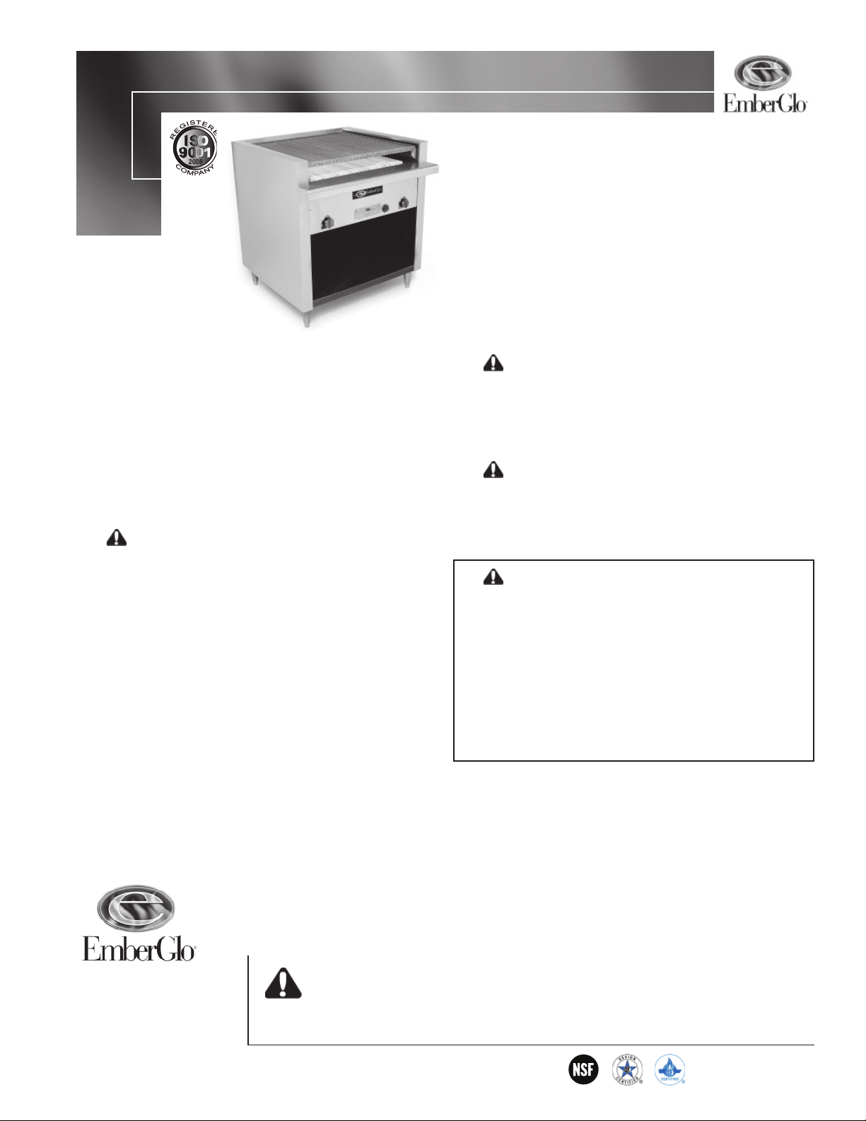
Open Hearth Broilers
Models 25, 31 & 41
PURCHASER: Retain these instructions for future use.
Post, in a prominent location near the broiler, instructions for
turning off gas valves in case gas odor is detected and any
other instructions as advised by your local gas supplier.
CAUTION: To avoid grease fi lter fi re hazard,
commercial kitchen exhaust hoods should be positioned at a
minimum of 3½ feet above the broiler cooking surface, as specifi ed by Commercial Grease Removal, Building Offi cials & Code
Administrators International Inc. and the National Mechanical
Code, 1990 Seventh Edition (or latest edition), Article 5, Section
M504.0, Table M504.3.2.
CAUTION: Cooking equipment should be used in
an environment protected by an automatic fi re suppression
system. Consult the National Fire Protection Association NFPA
Code 96 or the latest edition of Standards for Installation of
Equipment for Removal of Smoke and Grease-Laden Vapors
From Commercial Cooking Equipment.
WARNING: Improper installation, adjustment,
alteration, service or maintenance can cause property
damage, injury or death. Read the installation, operating
and maintenance instructions thoroughly before installing or servicing this equipment.
FOR YOUR SAFETY
Do not store or use gasoline or other fl ammable liquids
and vapors in the vicinity of this or any other appliance.
IF YOU SMELL GAS:
1. DO NOT TOUCH ELECTRIC SWITCHES
2. EXTINGUISH ANY OPEN FLAME
3. IMMEDIATELY CALL YOUR GAS COMPANY
AVOID ERROR IN PARTS SELECTION. When ordering use
complete EMBERGLO Part Number and Description. Furnish
Model Number, Bill of Material Number and Serial Number (if
available) from the specifi cation plate found on the product.
IMPORTANT: Availability of parts as well as specifi cations are
subject to change without notice. Please consult factory for
item availability.
SAFETY INFORMATION TERMS: The following terms are used to identify hazards, safety precaution of
special notations and have standard meanings throughout this manual. They are printed in all capital letters
using a bold type face as shown below, and preceded by the exclamation mark symbol. When you see the
safety alert symbol and one of the safety information terms as shown below, be aware of the hazard potential.
EmberGlo
A Div of Midco® International Inc.
4140 West Victoria Street
Chicago, Illinois 60646
toll free 866.705.0514
tel 773.604.8700
fax 773.604.4070
web www.emberglo.com
e-mail sales@emberglo.com
DANGER: Identifi es the most serious hazards which will result in severe personal injury or
death.
WARNING: Signifi es a hazard that could result in personal injury or death.
CAUTION: Identifi es unsafe practices which would result in minor personal injury or product and
property damage.
Quality Designed for Proven Performance
511
8448 24
Printed in USA
Page 2

Models 25, 31 and 41 - Installation
Gas Pressure
Requirements
Installation
GAS PRESSURE REQUIRED
Natural Gas Propane Gas
800 to 1,100 BTU/cu. ft 2,500 BTU/cu. ft.
5.0″ to 14″ W.C 11.0″ to 14.0″ W.C.
Table 1 - Gas Pressure Requirements
-------------------------------------------------------------------------
Clearance Instructions:
1. For use in non-combustible locations only - For use only on non-combustible counter tops,
where minimum clearance from sides and back is 6″ (153mm).
2. The appliance area must be free and clear of all combustible items.
3. The unit must be leveled before placing it in operation. Level the unit on an uneven surface
to prevent rocking, adjustable feet have been provided.
4. When using gas broiler, keep the appliance area free from obstructions that could block the
fl ow of fresh air for the ventilation and Flaretrol systems.
Floor model broilers are equipped with adjustable legs. Use an open-ended wrench on the bottom
hex of each leg to adjust the height and to level the broiler.
When an appliance is supplied on casters and is connected to the supply piping by means of a
connector for movable appliances, the operator must be aware of the restraints on the appliance and
if disconnection of the restraints is necessary to reconnect this restraint after the appliance has been
returned to its originally installed position.
For an appliance equipped with casters the following criteria must be met:
1. The installation shall be made with a connector that complies with the Standard or
Connectors for Movable Gas Appliances, ANSI Z21.69 - CSA 6.16, and a quick-disconnect
device that complies with the Standard for Quick-Disconnect Devices for Use With Gas
Fuel, ANSI Z21.41 - CSA 6.9.
2. Adequate means must be provided to limit the movement of the appliance without
depending on the connector and the quick-disconnect device or its associated piping to limit
the appliance movement
3 The location(s) where the restraining means may be attached to the appliance shall be
specifi ed.
The broiler is shipped with knobs unattached. To assemble knobs, align shaft fl ats with knob fl ats
and press on (no set screws are used). When pressing, reach under broiler and support valve shafts.
Do not hammer knobs as valve damage could occur.
Electrical Connections: The wiring diagram and electrical and gas connections are located behind the front plate of the broiler. To remove the front plate:
1. Slip the valve knobs from their stems (no set screws are used).
2. Remove the side screws holding the front plate.
3. Pulling from both sides at the bottom, snap out lower section and lift off.
Power supply for the Flaretrol system should be rated at 120 Volts, 60 Hz. with a current draw of
1.5 Amps maximum. Use rigid or fl exible conduit (fl exible type recommended for counter models);
splice each leg of the electrical supply line to one of the leads at the rear of the Flaretrol switch. Make
sure the broiler is electrically grounded using the grounding lug located adjacent to the conduit box.
Installation wiring and grounding of the broiler must conform to local codes or, in the absence
of local codes in the United States to National Electric Code, ANSI/NFPA 70 or latest edition; in
Canada, to Canadian Electrical Code, CSA Standard C22.2.
Gas Line Connection: Supplied loose with every broiler are a union, a Main Manual Shut-Off Valve
and a gas pressure regulator. The union is to be used for connecting the gas line to the unit and must
be located downstream of the Main Manual Shut-Off Valve and regulator. The Main Manual ShutOff Valve and the gas pressure regulator should both be mounted in an accessible location near the
broiler, with the Main Manual Shut-Off Valve located upstream of the regulator and the arrow on the
body of the regulator pointing in the direction of the fl ow. The Main Manual Shut-Off Valve must be
located so that the operator’s hand will not be exposed to fl ame or fl ue products when reaching for
the valve handle. Although the regulator may be mounted in any position, it is recommended that it
be located in a horizontal run of pipe with its diaphragm case level.
Supply line size should be suffi cient to provide full input at the broiler. For Model 25, use
1/2″ pipe for runs up to 100 ft. For Models 31 and 41, use 1/2″ pipe for runs up to 50 ft. and
3/4″pipe for runs of 50 ft. or more. For all broilers using PROPANE gas, 1/2″ pipe will be suffi cient for runs up to 100 ft.
2
EmberGlo A Division of Midco International Inc
8448 24
Page 3
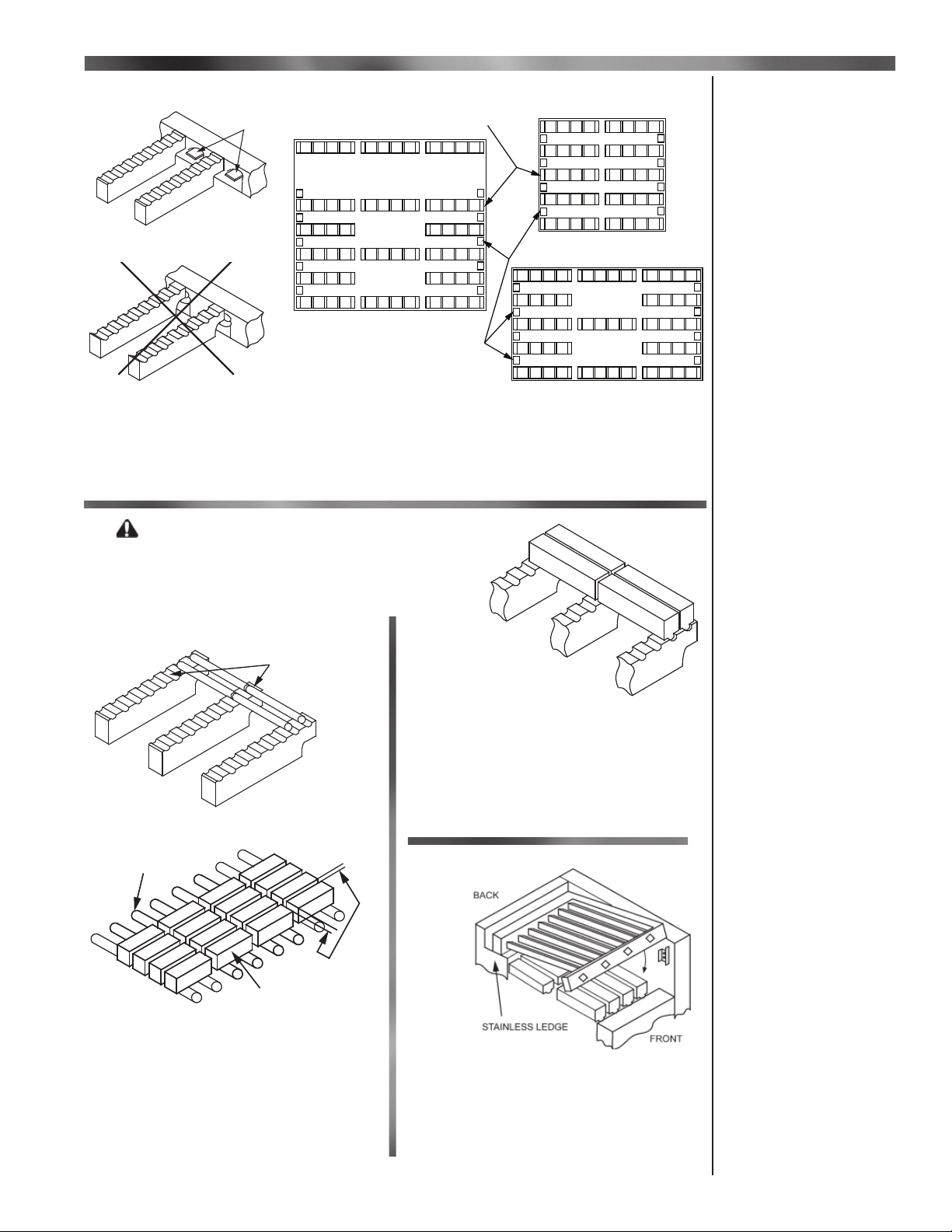
Models 25, 31 and 41 - Broiler Hearth Setup
IMPORTANT:
Placement of the Grate Support Bricks is identical for either Briquette or Barbriq set-up.
Burner Tips
(OPEN END TOWARD BURNER TIP)
CORRECT
INCORRECT
Figure 1
Grate Support Brick Placement
Grate Support Bricks
MODEL 25C, 25F
MODEL 41C, 41F
Burner Tips
MODEL 31C, 31F
Figure 2
Grate Support Brick Arrangements
Set grate support bricks in fi rebox. Be sure cut-out end of brick is placed midway between each
burner tip - NEVER directly in front of the tips.
Broiler Hearth Setup
Grate Support
Bricks Setup
CAUTION: When the Char Broiler
is HOT!! never attempt to change location
or remove grates during cooking. FlareUp can occur at anytime. Turn off the char
broiler and wait until it cools.
PLACE CERAMIC GRATE
RODS IN GROOVES
Figure 3
Ceramic Grate Rod
Placement
GRATE RODS
1/8" to 1/4"
SPACE
BRIQUETTES
Figure 4
Briquette Placement
Set ceramic briquette on grate rods. Be
sure to allow 1/8″ to 1/4″ space between
each briquette. Briquette should only cover
grate rod area of hearth. Briquette arranged
in columns (as shown) or staggered briquette
arrangements are acceptable.
Figure 5
Ceramic Barbriq
Placement
Place ceramic Barbriqs in grooves. The
featured design aligns automatically between
each Barbriq. Barbriqs should only cover
grate support brick area of hearth. Barbriqs
are arranged in columns (as shown) end to
end.
Figure 6
Cooking Grill ( All Models)
Install cooking grill by resting it on stainless ledge at rear and then lowering it onto
metal bracket at front.
Barbriq and
Briquette Setup
Grill Setup
8448 24
EmberGlo A Division of Midco International Inc
3
Page 4

Models 25, 31 and 41 - Installation
Installation
Continued
Use pipe joint compound resistant to Liquefi ed Petroleum Gases. Check the broiler piping and
valves for gas leaks by applying a weak liquid soap solution to unions and joints with the gas supply
on. Leakage will be indicated by the appearance of soap bubbles. Locate and correct all gas leaks
before proceeding.
WARNING: DO NOT USE OPEN FLAME.
During any pressure testing of the gas supply piping system at test pressures equal to or less
than 1/2 psi (3.45 ka), the Broiler must be isolated from the gas supply piping system by closing its
individual Main Manual Shut-Off Valve.
During any pressure testing of the gas supply piping system at test pressures in excess of 1/2 psi
(3.45 ka), the Broiler and its individual Main Manual Shut-Off Valve must be disconnected from that
system.
WARNING: EXPLOSION HAZARD. DO NOT USE OXYGEN FOR PRESSURE TESTING.
AN EXPLOSION COULD OCCUR DURING INITIAL START-UP
Manifold pressure taps are supplied for testing operating pressures and setting gas input. On
Model 25, the tap is located in the main manifold piping directly behind the Manual Burner Valve. On
Models 31 and 41, it is located in the pilot line behind the Manual Pilot Valve.
Each burner tip has been individually orifi ced for the correct gas input for NATURAL or PROPANE
gas.
BROILER MODEL 25C/25F 31C/31F 41C/41F
Number of burner tips 6 8 10
Capacity/Tip (BTU/Hr) 6,600 8,500 8,500
Max. BTU/Hr Input 39,600 68,000 85,000
NAT Gas Orifi ce Size #56 #54 #54
Manifold Pressure 4″ W.C. 4″ W.C. 4″ W.C.
PROP Gas Orifi ce Size #68 #65 #65
Manifold Pressure 10″ W.C. 10″ W.C. 10″ W.C.
Table 2 - BTU Capacity, Orifi ce Size and Manifold Pressure
USE OF PROPANE FOR GAS BROILERS
Model BTU/Hr LB of Propane Cylinder Hours of Use
Used/Hour Size Full On (approx.)
25* 39,000 0.48 lb 20# 9 Hr
40# 19 Hr
100# 48 Hr
31** 68,000 0.28 lb 40# 11 Hr
100# 28 Hr
41*** 85,000 0.22 lb 100# 22 Hr
Minimum size Cylinder: * Model 25 - 20# / ** Model 31 - 40# / *** Model 41 - 100#
Table 3 - Propane per Hour Usage
Ventilation: A suitable power or gravity ventilating system must be used in conjunction with the
EmberGlo Open Hearth Broiler.
Power Types: Either of the two types of power ventilators - the overhead hood type or under shelf
exhaust type - may be used. The latter offers simplicity of installation and minimum cleaning expense.
Both require fl ame-proof fi lters for grease removal. Connect the ventilator to a duct of suitable size.
The exhaust blower must be capable of removing a minimum of 325 CFM of air per square ft. of
broiler surface; specifi cally: a fan capacity of 2,000 CFM is required for the Model 41, 1400 CFM for
the Model 31, and 775 CFM for the Model 25.
Gravity Types: Since no power exhaust is used, the gravity ventilating system is adequate only in
certain conditions. It is only practical in single story buildings not surrounded by higher structures. A
large straight duct, equal to a minimum of half the grill area, must be carried upward from a hood over
the broiler to a height of four feet above the highest point of the roof. It should be equipped with a
rotary outlet. The hood must extend at least 12 inches beyond each side of the grill. Since no fi lters
are used, periodic inspection and cleaning of the hood and duct work is especially important.
4
EmberGlo A Division of Midco International Inc
8448 24
Page 5

Models 25, 31 and 41 - Operations, Installation & Maintenance
FOR PROPER OPERATION, ALL VENTILATING SYSTEMS REQUIRE
AN ADEQUATE SUPPLY OF FRESH AIR INTO THE ROOM.
SEE IMPORTANT NOTE REGARDING EXHAUST HOODS ON FRONT
PAGE OF THIS MANUAL.
-------------------------------------------------------------------------
Instructions for turning on the Broiler:
The two pilots are located under the front panel on the right and left hand sides.
1. Make sure that the Main Manual Shut-Off Valve is in the ON position and the
Manual Burner Valve(s) are in the OFF position.
2. Turn Manual Pilot Valve ON and use a match or long lighter to ignite the pilots.
3. Once the pilot(s) is lit turn on the manual burner valves.
4. If the fl ame fails to light or goes out, turn off the manual burner valves and the pilot
valves. Wait for 5 minutes. Repeat from step 2.
If necessary, a few briquettes may be removed from the hearth for easy access to the pilot; they
should be replaced before operating the broiler.
If the pilot fl ame is too short or too long, remove the Manual Pilot Valve handle and adjust the slotted
screw in the valve stem for a suitable fl ame.
Preheating: The Model 25 broiler has a single Manual Burner Valve which controls all six main burners. Models 31 and 41 have two Manual Burner Valves, one for each side of the broiler. Preheat the
broiler with the Manual Burner Valves wide open for a short period, until a dull red glow is visible on the
lower surface of the Barbriq. After preheating, reduce valve settings to the lowest fl ame required to
maintain the glow on each side of the broiler hearth - not necessarily in the center. DO NOT broil with
the Manual Burner Valves wide open, or with excessively bright Barbriqs on the hearth. Maximum
valve setting is used only for preheating.
Installation
Continued
Operation
Continued
Flaretrol: Turn the Flaretrol switch ON when an excessive grease fl are develops. When there is no
fl are, turn it OFF. Continuous operation of the Flaretrol will not damage the motor, but it will needlessly
lower the temperature at the grill.
If excessive fl are develops which cannot be adequately controlled by the Flaretrol, move meat to
another area of the grill. Do not overload the grill; leave suffi cient space between the pieces of meat to
allow the meat to be shifted and smoke to exit. If cooking during a power failure, the Flaretrol function
is lost; therefore take special care to avoid excessive grease fl are-up.
During heavy periods of broiling, reduce the valve settings to compensate for increased heat from
grease fl are.
To Shut Off: Turn the Manual Burner Valve(s) to the OFF position. Turn the Manual Pilot Valve to
the OFF position.
-------------------------------------------------------------------------
IMPORTANT: Disconnect power supply prior to cleaning or servicing.
Depending on the amount of use, periodic cleaning is necessary. Turn the Main Knobs on high for
30 minutes. Turn the broiler off and wait for a complete cool down. Brush or vacuum the heart. Be
sure that the pilot areas are clean and clear of ash and burned matches. Because of the incinerator
action of the hearth, grease does not normally accumulate under the grate; however, periodically the
Barbriqs or ceramic rods should be removed and the hearth cleaned, either by brushing or vacuuming. Wipe grease splatter from the top and adjacent surfaces.
The Flaretrol motor features permanently lubricated ball bearings and requires no routine
oiling.
Keep the area around the broiler free of combustible materials. Since the combustion and
Flaretrol air is taken from the front of the unit, do not obstruct the free fl ow of air to the front.
CAUTION: On the counter models, do not store cooking utensils, mitts, towels or anything
combustible between broiler and counter top. Restricting air fl ow, particularly on counter models,can
cause over-heating and premature motor failure.
CAUTION: On fl oor models, do not store combustible materials such as paper, fabric,
cooking oils, or any other fl ammable liquids in fl oor models’ stainless steel storage shelf.
Do not obstruct the fresh air supply into the room or the ventilating system. For maintenance
and service, refer to your local gas service or utility company.
-------------------------------------------------------------------------
Maintenance
8448 24
EmberGlo A Division of Midco International Inc
5
Page 6

Models 25, 31 and 41 - Broiling Techniques
Broiling Techniques
Open hearth broiling on the EmberGlo has great advantages over other methods of cooking
meats, fi sh, and poultry. It is fast and gives a seared surface to the food, improving both appearance
and taste. It uses no grease except that which is in the food itself.
The temperature at the grill surface, as in all cooking processes, is most important. It is possible
to create various zones of temperature ranging from 350°F to 750°F by adjusting the Main Knobs
on the EmberGlo Broiler. The higher temperatures impart the seared dark brown surface that some
customers prefer, and speed cooking time. The lower temperatures are for thick cuts of meat which
must be well done without excessive surface charring. Excessive grill temperatures should be avoided. The temperature at the grill surface is the determining factor in cooking-the hotter the grill, the
shorter the cooking time, and vice versa.
Start broiling by placing food products on the center of the cooking grill (hottest area) and fi nish
in the cooler zone (sides). Following are some helpful hints for getting the most from your EmberGlo
Broiler.
1. Thick pieces of meat, whole fi sh and half chickens should be broiled over lower
heat to prevent undue charring of the surface while the center is being cooked. This
should be done over a cooler zone on the grill.
2. In broiling large quantities of strip steaks simultaneously, excess fat should be
trimmed off. If thick steaks are being broiled, sear at high fi re and fi nish in a cooler
zone, particularly if medium or well done steak is desired.
3. Fillets Mignon and other lightly fatted meats may be brushed with butter or garlic
butter before broiling or when fi rst placed over the fi re. This gives a more even
browning to the meat, and prevents excessive surface charring.
4. Meat or fi sh should not be salted before broiling in order to prevent the rapid loss of
natural juices. However, poultry should be salted before placing on the grill to
prevent too charred a surface.
5. Raw pork must,of course, be cooked throughout. This means slow broiling at lower
temperatures. Ribs, chops, and other cuts are delicious when so broiled. Due to the
time involved, it is often advisable to partly cook the ribs and double chops on the
EmberGlo Broiler and then fi nish-broiling on a standard top broiler.
6. Fish requires basting two or three times during the broiling period. Butter, margarine
or salad (cooking) oil may be used. Some chefs prefer a basting sauce or lemon
juice and spices mixed with oil. Others recommend supplying the customer with
special sauces at the table. The purpose of basting with oils is to speed browning of
the quickly broiled, moist fl esh.
7. Lobster is often prepared by the open hearth method. Basting is required but the
use of lobster racks makes this simple. Many establishments feel this is the best
possible method of broiling lobster.
8. Veal is seldom broiled because the lack of fat tends to make the meat dry and
“chewy.” Connective tissue in veal usually requires a longer cooking time than is
desired with broiling.
-------------------------------------------------------------------------
6
EmberGlo A Division of Midco International Inc
8448 24
Page 7

Cooking Guide
This table gives the approximate times for broiling various cuts and thicknesses of different meats on
the EmberGlo Broiler.
Cooking time is given for raw meats.
Cooking Time in Minutes
Thickness Rare Medium Well
BEEF
Filet Mignon, Porterhouse 1″ 6 8 10
T-Bone, Club, Rib 1½″ 9 10 13
Sirloin 2″ 16 18 21
Strip Sirloin ¾″ 4 6 8
Hamburger, Ground Chuck,
or Round ½″ 2 4 8
LAMB*
Center cut loin, rib 1″ -- 10 15
Sirloin chops, double rib 1½″ -- 15 21
English chops 2″ -- 20 25
Shoulder chops and leg steaks 1″ -- 10 15
Lamb riblets or Mutton chops 1″ -- 12 18
Cooking Guide
PORK*
Spare ribs -- -- -- 30-40
Single chops ½″ -- -- 15
Double chops 1½″ -- -- 25
Thickness Well
FISH
Fillets (times are for one ¼″ 5
side of fi llet only do not turn) ½″ 6
1″ 8
Fish steaks ½″ 3
1″ 5
1½″ 8
Whole fi sh, dressed 3″ 5
Split (times are for one 1½″ 6
side of split only - do not turn) 2″ 9
POULTRY
Broiling chickens ¾ lb. 9
(Ready-to-broil weight 1 lb. 11
for half chickens) 1½ lbs. 14
8448 24
* These times can be shortened by partial pre-or post- cooking.
EmberGlo A Division of Midco International Inc
7
Page 8

Warranty
Warranty
Midco® International Inc Limited Warranty Policy
Exclusions Terms, Customer Requirements and Instructions
All claims should be fi led through Warranty Central.
Call factory for information (773 604 8700)
Only Authorized Service Providers are authorized to provide Limited Warranty service on all
EmberGlo
®
, a Division of Midco® International Inc., food equipment as described under and Midco®
International Limited Warranty Policy. A list of providers can be found on our web site: www.emberglo.com
Provisions:
In lieu of an implied warranty, all repairs and replacement parts furnished under our Limited Warranty
shall be f.o.b. point of distribution, but the owner must pay the necessary freight, delivery and labor
costs involved when required. Any Federal, State or Local taxes are also extra. This Limited Warranty
is effective for a period of one year from date of installation. EmberGlo
®
Char Broilers and EmberGlo®
Electric Food Preparation Equipment manufactured by Midco International, sold under the EmberGlo
trademark, are guaranteed to be free from defect in material and workmanship under normal use and
service for a period of 1 (one) year after the date of original installation. Midco’s obligation under this
Limited Warranty Policy shall be limited to repairing or replacing, at our option, any part of said equipment which Midco examination shall disclose to its satisfaction to be thus defective.
Exclusions:
This Limited Warranty Policy does not apply to damages resulting from accident, misuse, abuse or alteration, nor does it apply to limed steam generators, nor does it apply to any consequential damages.
Most geographical areas require the use of distilled or demineralized water. Tap water is permissible
only with ES Series Steamers. Nor does it apply to Barbriq’s
®
, briquettes, or rods used in gas broilers.
Midco’s obligation will be the replacement of the product or parts removed.
Terms:
Under the terms of this Limited Warranty Policy, models considered portable (devices with cords and
plug caps such as EmberGlo Steamers) must be taken or returned to the nearest service provider,
transportation prepaid, returned transportation collect. Non-portable units with permanent wiring will
be serviced on the customer’s premises. Under these terms, Midco agrees, within the terms of this
Limited Warranty period, to make all repairs at no charge by the authorized service provider. Labor
and mileage charges submitted by any other provider not authorized will be the responsibility of the
customer.
Customer Requirements:
All charges related to repairs made one (1) year after the date of original installation, during the Limited Warranty period will be the responsibility of the customer. The product registration information is
located on the product I.D. plate.
®
If a part is defective due to workmanship or materials and is removed from the product within the applicable warranty period and returned to Midco in accordance with the following procedure described,
Midco will, at its option, either repair or replace the part.
Call the factory for Instructions on returned goods.
No equipment may be returned without written authorization from MIDCO. Returned goods
must be shipped prepaid to the factory.
WARNING: Improper installation and use of this product could result in personal or
property injury.
8
toll free: 866 705 0515 - tel: 773.604.8700 - fax: 773.604.4070 - web: www.emberglo.com - e-mail: sales@emberglo.com
EmberGlo A Division of Midco International - 4140 West Victoria Street - Chicago, Illinois 60646
511
8448 24
Printed in USA
 Loading...