


Revision
1.0
user manual
AMOS-1000
Universal Compact
Chassis System, Supporting
Mini-ITX Embedded Boards

Copyright and Trademarks
Copyright © 2009 VIA Technologies Incorporated. All rights reserved.
No part of this document may be reproduced, transmitted, transcribed, stored in a
retrieval system, or translated into any language, in any form or by any means, electronic,
mechanical, magnetic, optical, chemical, manual or otherwise without the prior written
permission of VIA Technologies, Incorporated.
All trademarks are the property of their respective holders.
PS/2 is a registered trademark of IBM Corporation.
Disclaimer
No license is granted, implied or otherwise, under any patent or patent rights of VIA
Technologies. VIA Technologies makes no warranties, implied or otherwise, in regard to
this document and to the products described in this document. The information provided
in this document is believed to be accurate and reliable as of the publication date of this
document. However, VIA Technologies assumes no responsibility for the use or misuse of
the information in this document and for any patent infringements that may arise from the
use of this document. The information and product specifications within this document are
subject to change at any time, without notice and without obligation to notify any person
of such change.
Regulatory Compliance
FCC-A Radio Frequency Interference Statement
This equipment has been tested and found to comply with the limits for a class A digital
device, pursuant to part 15 of the FCC rules. These limits are designed to provide
reasonable protection against harmful interference when the equipment is operated in a
commercial environment. This equipment generates, uses, and can radiate radio
frequency energy and, if not installed and used in accordance with the instruction manual,
may cause harmful interference to radio communications. Operation of this equipment in a
residential area is likely to cause harmful interference, in which case the user will be
required to correct the interference at his personal expense.
Notice 1
The changes or modifications not expressly approved by the party responsible for
compliance could void the user's authority to operate the equipment.
Notice 2
Shielded interface cables and A.C. power cord, if any, must be used in order to comply
with the emission limits.
Tested To Comply
With FCC Standards
FOR HOME OR OFFICE USE
Battery Recycling and Disposal
Only use the appropriate battery specified for this product.
Do not re-use, recharge, or reheat an old battery.
Do not attempt to force open the battery.
Do not discard used batteries with regular trash.
Discard used batteries according to local regulations.
II
Safety Precaution
Do’s
o Always read the safety instructions carefully.
o Keep this User's Manual for future reference.
o All cautions and warnings on the equipment should be
noted.
o Keep this equipment away from humidity.
o Lay this equipment on a reliable flat surface before setting
it up.
o Make sure the voltage of the power source and adjust
properly 110/220V before connecting the equipment to the
power inlet.
o Place the power cord in such a way that people cannot
step on it.
o Always unplug the power cord before inserting any add-on
card or module.
o If any of the following situations arises, get the equipment
checked by authorized service personnel:
o The power cord or plug is damaged.
o Liquid has penetrated into the equipment.
o The equipment has been exposed to moisture.
o The equipment has not worked well or you cannot
get it work according to User's Manual.
o The equipment has dropped and damaged.
o The equipment has obvious sign of breakage.
Don’ts
o Do not leave this equipment in an environment
unconditioned or in a storage temperature above 60°C
(140°F). The equipment may be damaged.
o Do not leave this equipment in direct sunlight.
o Never pour any liquid into the opening. Liquid can cause
damage or electrical shock.
o Do not place anything over the power cord.
o Do not cover the ventilation holes. The openings on the
enclosure protect the equipment from overheating
III
IV
Box Contents
1 x Screws package for boards
1 x Screws package for mount bracket
1 x Cable tie and tie mount package
1x Left wall mount bracket
1x Right wall mount bracket
1 x 2-pin Phoenix connector to DC jack cable
1 x SATA HDD cable
1 x Washer rubber package
We have carefully inspected the product mechanically and
electrically before shipping. It should be free of cosmetic damage
and in perfect working order upon receipt. As you unpack the
product, check it for signs of shipping damage (e.g., damaged box,
scratches, dents, etc). If it is damaged or it fails to meet the
specifications, notify our service department or your local sales
representative immediately. Also, please notify the carrier. Retain
the shipping carton and packing material for inspection by the
carrier. After inspection, arrangements will be made to repair or
replace the unit
Note:
Note:
Note:Note:
If any of these items are missing or damaged, contact your
distributor or sales representative immediately.

V
Ordering Information
Model Number Description
AMOS-1000-1MZZA1 Embedded Chassis System for Mini-ITX
AMOS-1000-1MSZA1 Embedded Chassis System for Mini-ITX
AMOS-1000-1MRZA1 Embedded Chassis System for Mini-ITX
AMOS-1000-1MSRA1 Embedded Chassis System for Mini-ITX
boards, with 120W DC to DC power board,
rear Reserved Cutouts for 1 x DVI, 1 x DIO, 1
x D-sub 26 pin connector, 4 x COM, 4 x USB
boards, with 120W DC to DC power board,
storage chassis, rear Reserved Cutouts for 1
x DVI, 1 x DIO, 1 x D-sub 26 pin connector,
4 x COM, 4 x USB
boards, with 120W DC to DC power board,
riser chassis, rear Reserved Cutouts for 1 x
DVI, 1 x DIO, 1 x D-sub 26 pin connector, 4
x COM, 4 x USB
boards, with 120W DC to DC power board,
storage chassis, riser chassis, rear Reserved
Cutouts for 1 x DVI, 1 x DIO, 1 x D-sub 26
pin connector, 4 x COM, 4 x USB
Optional Accessories
Power Adapter
99G63-020106 AC-to-DC adapter, 19V 90W
Power cables for power adapter
99G33-02058C power cable, 180 cm, USA type
99G33-02057C power cable, 180 cm, Europe type

T
ABLE OF
C
ONTENTS
1 Product Overview............................................................................................... 1
Key Features...........................................................................................................2
Specification ...........................................................................................................4
Power Supply ........................................................................................................ 5
Environment Specifications ............................................................................ 5
AMOS-1000 Chassis Dimensions ................................................................ 6
The Front Plate......................................................................................................7
The Rear Plate........................................................................................................7
2 Accessories .............................................................................................................9
I/O Boards (Optional) .....................................................................................10
LPC-01/LPC-02...............................................................................................10
PUSB-01.............................................................................................................10
Cables......................................................................................................................11
LPC cable..........................................................................................................11
USB cable .........................................................................................................11
Power Cable ...................................................................................................12
Digital I/O cable............................................................................................12
DC Input connector converter cable .................................................13
Display Modules (Optional)..........................................................................14
DVI-03................................................................................................................14
DVI-04................................................................................................................14
DVI-05................................................................................................................15
Cable for DVI modules ...................................................................................16
DVI cable..........................................................................................................16
USB Module (Optional)..................................................................................17
WLAN USB......................................................................................................17
Cable for WLAN module...............................................................................17
WLAN USB cable .........................................................................................17
3 Basic installation .................................................................................................19
Removing the top Cover of the Chassis.................................................20
Replacing the Power Board .........................................................................22
Installing the Hard Disk Drive ......................................................................25
Installing the LPC-01 (or LPC-02) expansion module......................30
Installing the PUSB-01 expansion module ............................................32
Installing the WLAN USB module.............................................................34
Installing the Mainboard................................................................................36
VI

Installing the CF card or Mini-PCI card....................................................38
Installing the Riser and PCI Cards ..............................................................40
Installing the CD Drive (Optional).............................................................45
Installing the Hard disk drive in Bottom Casing (Optional)..........49
Installing the AMOS-1000 Wall Bracket .................................................53
A Exploded Diagram ............................................................................................55
B Compatible Mini-ITX boards ...................................................................57
C Cable Tie Location Illustration ......................................................................59
VII

VIII

1
Product Overview
1

The AMOS-1000 can be easily expanded to support application
specific requirements thorough its stackable sub-system chassis
expansion kits (riser chassis and storage chassis). The modularity
and expandability of the AMOS-1000 chassis makes it ideally
suitable for diversified embedded system applications requiring the
combination of high processor performance, expandability, and
low costs (such as machine automation, and industrial plant and
cabinet integration).
An optional PCI riser card and numerous additional interfaces can
be easily installed to the AMOS-1000 chassis through the PCI riser
sub-system chassis expansion kit. The storage sub-system chassis
expansion kit enables the AMOS-1000 to support up to two
additional 2.5” HDD and a slim Optical Disk Drive (ODD). The
storage sub-system chassis expansion kit can be mounted to the
bottom of the AMOS-1000 chassis.
The AMOS-1000 chassis is built with a DC 120W power board
that accepts a wide range of DC power input from 12V to 24V.
Developers can also choose to replace the default power board
with the optional 1U ATX PSU. The modularity and expandability
of the AMOS-1000 chassis and its stackable sub-systems, enables
longevity, easy maintenance and serviceability that protects the
customer’s investment.
KEY FEATURES
UUUUniversal
niversal compact embedded chassis compatible with a wide
niversalniversal
selection of
selection of Mini
selection of selection of
• Open front I/O area makes it easy to support a wide variety of
Supports additional sub
Supports additional sub----system chassis expansion kits
Supports additional subSupports additional sub
• An optional PCI riser sub-system chassis expansion kit can be
• An optional storage sub-system chassis expansion kit can be
compact embedded chassis compatible with a wide
compact embedded chassis compatible with a wide compact embedded chassis compatible with a wide
Mini----ITX
ITX embedded boards
MiniMini
I/O port configurations
added to support up to two PCI cards.
added to support up to two additional hard disks and one slim
optical drive.
embedded boards
ITXITX
embedded boards embedded boards
system chassis expansion kits
system chassis expansion kitssystem chassis expansion kits
2

Flexible configurations of I/O modules
Flexible configurations of I/O modules
Flexible configurations of I/O modulesFlexible configurations of I/O modules
• Abundant pre-punched removable I/O port cutouts at the rear
to support various I/O ports demands
• Available I/O modules include:
o LPC-01: four RS-232 ports
o LPC-02: two RS-232 and two RS-232/422/485
o PUSB-01: four ports Powered USB (5V power)
o DVI-03: DVI module (compatible with EPIA EK and EPIA EN)
o DVI-04: DVI module (compatible with EPIA SN)
Modular power supply design
Modular power supply design
Modular power supply designModular power supply design
• Removable default power board supports DC 12V ~ 24V
• Supports 1U ATX power supplies (3.25" W x 1 5/8" H x 6" D)
WiFi networking option
WiFi networking option
WiFi networking optionWiFi networking option
• Optional WLAN module
• Designated mounting and antenna holes in AMOS-1000
chassis
Multiple mounting solutions:
Multiple mounting solutions:
Multiple mounting solutions:Multiple mounting solutions:
• Secure wall mounting with special mounting bracket
• No-slip, shock resistant desktop mounting with special rubber
feet
3

SPECIFICATION
• Construction: heavy-duty steel
• Disk Drive Capacity: one internal 2.5 inch Hard Disk Drive bay
• LED Indicators on front panel: single-color LED for Power
(green) and HDD activity (red).
• Front I/O Interfaces: removable I/O plate
• Rear I/O Interfaces: pre-punched openings reserved for one D-
Sub 26-pin connector, one DIO port, one DVI port, four COM
ports, and four powered USB ports
• Cooling System: one 50 mm x 50 mm (13.0 CFM) cooling fan
• Weight: 2.3 kg (5.07lb)
• Dimensions (W x H x D): 287 x 70 x 245 mm (11.3" x 2.8" x 9.6")
4
POWER SUPPLY
The AMOS-1000 accommodates a DC 120W power board. The
detail specification is as follows:
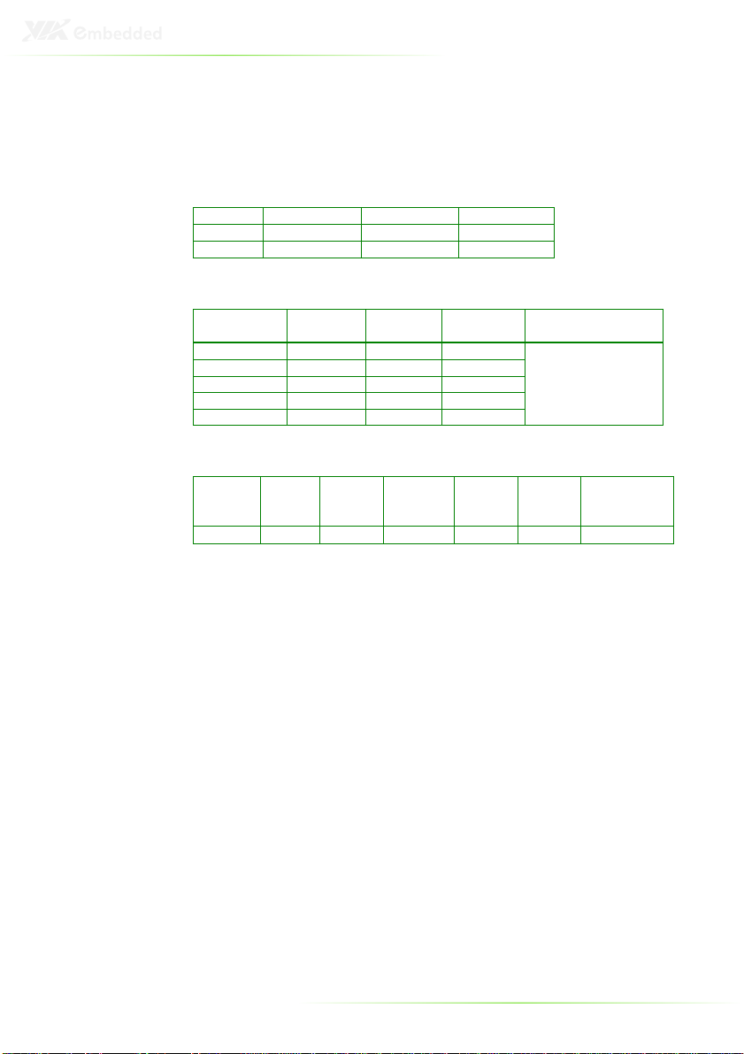
DC Input
DC Input
DC InputDC Input
Input Minimum Nominal Maximum
Voltage 11.4V ~ 22.8V 12V ~ 24V 12.6V ~ 25.2V
Current 5.24A ~ 10.84A
DC Output Voltage
DC Output Voltage
DC Output VoltageDC Output Voltage
Input Minimum Nominal Maximum
+5V_SB 4.75V 5V 5.25V
+3.3V 3.14V 3.3V 3.47V
+5V 4.75V 5V 5.25V
+12V 11.4V 12V 12.6V
Power Good 4.75V 5V 5.25V
DC Output
DC Output Current
DC Output DC Output
+5V_SB +3.3V +5V +12V -12V
2A 6A 6A 5A 200mA 0.1A 120W
Current
CurrentCurrent
Maximum
Combined Power
120W
Power
Good
Maximum
Combined
Power
ENVIRONMENT SPECIFICATIONS
• Temperature:
o Operating Temperature 0 to 45° C (32 to 113° F)
o Storage Temperature -20 to 65° C (-4 to 140° F)
• Relative Humidity: 0% ~ 90% @ 45° C (non-condensing)
• Vibration During Operation:
o Up to 1 Grms, IEC 60068-2-64, random, 5~500 Hz,1 oct./min.,
1hr/axis
• Shock During Operation:
o 20 G, IEC 60068-2-27, half sine, 11ms duration (Operation)
5

AMOS-1000 CHASSIS DIMENSIONS
6

THE FRONT PLATE
The front panel features an open I/O window that can support
various I/O configurations. There is also a system Power Button
and two LEDs. When the system power is on, the POWER LED is
always Green. When the Hard Disk Drive (HDD) is transmitting
data, the red HDD LED blinks.
THE REAR PLATE
The rear face features reserved cutouts for:
• Four USB PlusPower ports (PUSB-01) - P1~P4
• Four COM ports (LPC-01 or LPC-02) – COM1~COM4
• One 9-pin D-sub (DIO) - DIO
• One DVI port (DVI-03 or DVI-04) - DVI
• One 26-pin D-sub – PRINT
• One Wireless LAN Antenna - ANT
7

8

2
Accessories
9
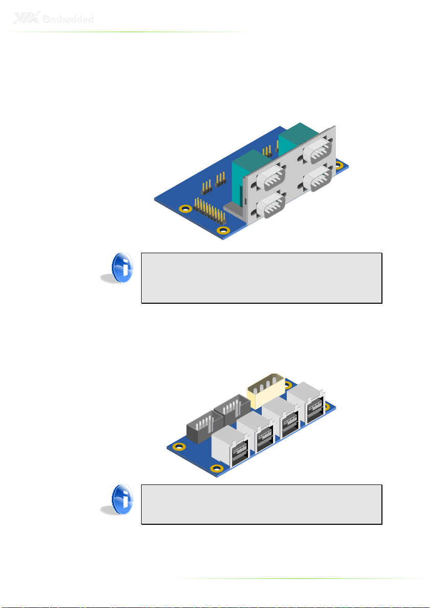
I/O BOARDS
LPC-01/LPC-02
Note:
Note:
Note:Note:
1. LPC-01: Expansion module for four RS232 ports (5V or 12V)
2. LPC-02: Expansion module for two RS232 ports and two
RS232/422/485 ports (5V or 12V)
PUSB-01
(O
PTIONAL
)
Note:
Note:
Note:Note:
PUSB-01: Expansion module for four USB PlusPower (12V)
connectors
10
CABLES
LPC cable
Part # 99G33-120091
USB cable
Part # 99G33-19022
11

Power Cable
Part # 99G33-02073F
Digital I/O cable
12

SATA cable
Part # 99G33-240103
DC Input connector converter cable
Part # 99G33-250073
13

DISPLAY MODULES
(O
PTIONAL
DVI-03
DVI-03 is compatible with EPIA-EK and EPIA-EN.
DVI-04
DVI-04 is compatible with EPIA-SN.
)
14
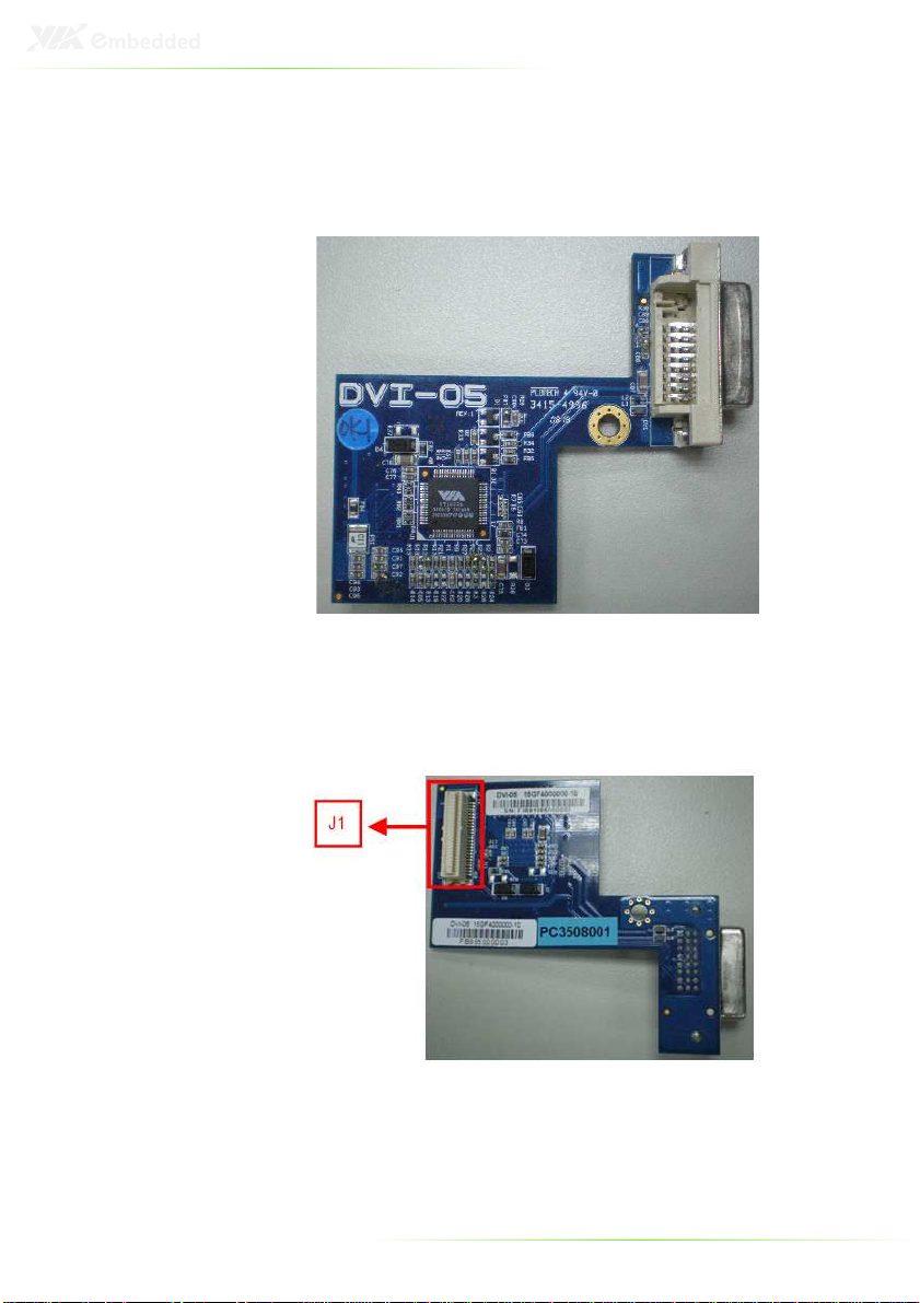
DVI-05
DVI-05 is compatible with M700.
Top View
Bottom View
15

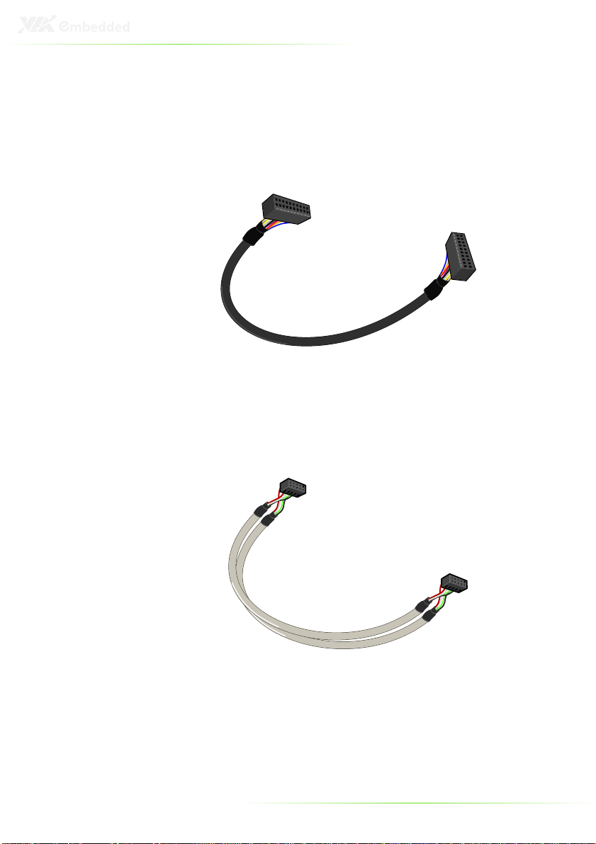
CABLE FOR DVI MODULES
DVI cable
Part # 99G33-150011
16

USB MODULE
(O
PTIONAL
)
WLAN USB
CABLE FOR WLAN MODULE
WLAN USB cable
17

18

3
Basic installation
19
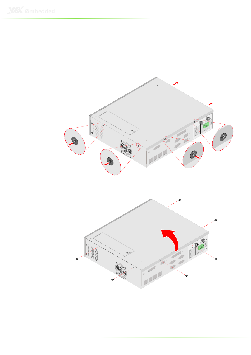
REMOVING THE TOP COVER OF THE
CHASSIS
Step 1
Step 1
Step 1Step 1
Remove the screws on the front, rear, right and left side.
20

Step
Step 2222
Step Step
Pull upwards from the rear side of top cover.
21

REPLACING THE POWER BOARD
The AMOS-1000 includes a VIA PWB-M120 120 Watt DC-to-DC
power board. An optional 1U Micro ATX power supply module is
also available. Two thumb screws on power supply tray provide
easy maintenance access to the power board or Micro ATX power
supply.
To exchange the power board or Micro ATX power supply,
proceed as follows:
Step 1
Step 1
Step 1Step 1
Ensure that the power cable is unplugged and remove the top
cover.
Step
Step 2222
Step Step
Unplug the 20-pin power connector from the main board.
22

Step
Step 3333
Step Step
Unscrew the two thumb screws of power tray then pull the
power tray out.
Step
Step 4444
Step Step
Loosen the four screws to pull up the power board. And remove
the pre-punched I/O cutouts on the face of the power tray
23

Step
Step 5555
Step Step
Put the 1U Micro ATX power supply module into the power tray.
Then fasten two screws through the bracket of power module
onto the power tray
Step
Step 6666
Step Step
Fasten four screws onto the rear plate of power tray to the 1U
Micro ATX power supply module.
Step
Step 7777
Step Step
Insert the power tray into the chassis and secure the tray with the
thumb screws.
Step
Step 8888
Step Step
Plug the 20-pin power connector to the main board
24

INSTALLING THE HARD DISK DRIVE
The AMOS-1000 comes with a shock proof bracket for installing a
SATA 2.5 inch HDD inside the chassis.
Step 1
Step 1
Step 1Step 1
To install the SATA 2.5” internal HDD, remove four screws of the
access cover on the bottom side of the chassis.
25

Step 2
Step 2
Step 2Step 2
Remove the chassis bottom cover plate.
26

Step
Step 3333
Step Step
On the inner side of the bottom cover is the HDD bracket.
Unscrew the four screws to remove the HDD mounting bracket.
27

Step 4
Step 4
Step 4Step 4
Insert the disk drive into the proper location of the bracket and
secure them with the provided screws.
28

Step
Step 5555
Step Step
Connect the SATA cable to the hard disk drive.
Step
Step 6666
Step Step
Connect the SATA power cable to the power board.
Step
Step 7777
Step Step
Mount the hard disk bracket onto the inside of the access cover
Step
Step 8888
Step Step
Replace the access cover and fasten it with four screws.
29

INSTALLING THE LPC-01 (OR LPC-02)
EXPANSION MODULE
The AMOS-1000 supports either the LPC-01 or LPC-02. The LPC01 adds four RS-232 COM ports. The LPC-02 adds two RS-232
COM ports and two RS-232/RS-422/RS-485 switchable COM ports.
To install the expansion module, please proceed as follows:
Step 1
Step 1
Step 1Step 1
Remove the pre-punched D-sub 9-pin I/O cutouts with the “COM”
label on the rear face of Chassis. File down any rough edges if
necessary.
Step 2
Step 2
Step 2Step 2
Fasten the expansion module onto the chassis with the four
screws provided.
30

Step
Step 3333
Step Step
Fasten the I/O connector onto the rear face of the chassis with the
eight nuts provided.
Step
Step 4444
Step Step
Connect the LPC cable to the expansion module and the LPC pin
header on the main board.
31

INSTALLING THE PUSB-01 EXPANSION
MODULE
The AMOS-1000 supports the PUSB-01 expansion module. The
PUSB-01 adds four USB PlusPower ports. To install the expansion
module, proceed as follows:
Step 1
Step 1
Step 1Step 1
Remove the pre-punched powered USB I/O cutouts printed with
“USB” on the rear face of the chassis.
Step 2
Step 2
Step 2Step 2
Fasten the expansion module onto the chassis with the four
screws provided.
32

Step 3
Step 3
Step 3Step 3
Connect the 4-pin power connector from the power board to the
expansion module.
Step 4
Step 4
Step 4Step 4
Connect the USB signal cable to the expansion module and USB
pin header on the main board
33

INSTALLING THE WLAN USB MODULE
The AMOS-1000 has a designated mounting space for the
optional WLAN module. Refer to the following instructions to
install the WLAN Module.
Step 1
Step 1
Step 1Step 1
Mount the WLAN module to the AMOS-1000 chassis.
Step
Step 2222
Step Step
Secure it with two screws. Connect the WLAN antenna cable to
the mini RF connector on the WLAN module.
34

Step
Step 3333
Step Step
Locate the WLAN antenna hole and install the WLAN antenna
Step
Step 4444
Step Step
Connect the WLAN USB cable to the Mini-ITX board and the mini
USB connector on the WLAN module
35
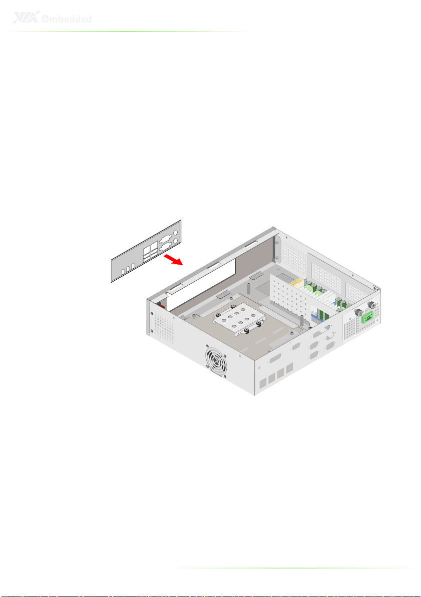
INSTALLING THE MAINBOARD
The AMOS-1000 supports a wide selection of VIA EPIA and VB
series Mini-ITX form factor boards. (see Figure 2.3)
Step 1
Step 1
Step 1Step 1
First, install all needed components to the mainboard (e.g., the
CPU cooler, RAM, CF card, mini PCI module, etc.)
Step 2
Step 2
Step 2Step 2
Remove the flat I/O shield plate in the front of chassis and replace
it with I/O shield of Mini-ITX main board
36
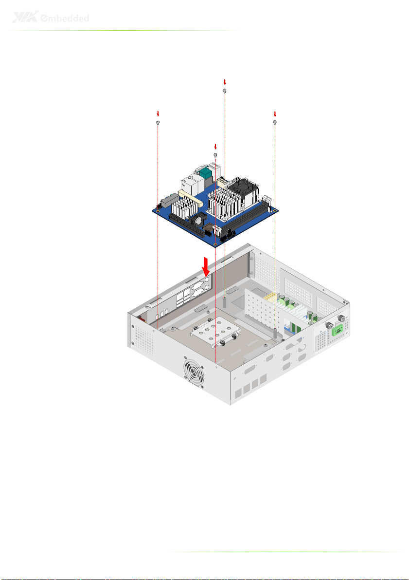
Step
Step 3333
Step Step
Fasten the Mini-ITX board onto the chassis with the provided
screws.
Ste
Step
p 4444
SteSte
p p
Connect the 20-pin power connector from the power board to
the Mini-ITX board.
Step
Step 5555
Step Step
Connect the power LED, HDD LED and power switch wire from
the chassis to the Mini-ITX board
37

INSTALLING THE CF CARD OR MINI-PCI
CARD
The AMOS-1000 bottom access cover enables quick access to the
CF and Mini-PCI socket locations on the bottom of various VIA
Mini-ITX boards. Refer to the following instructions to install the CF
card or Mini-PCI card.
Step 1
Step 1
Step 1Step 1
First remove the four screws from the bottom access cover.
38

Step 2
Step 2
Step 2Step 2
Remove the bottom access cover.
Step 3
Step 3
Step 3Step 3
Install or replace the CF card or Mini-PCI card.
Step 4
Step 4
Step 4Step 4
Replace the bottom access cover and fasten it with four screws.
39

INSTALLING THE RISER AND PCI CARDS
Step 1
Step 1
Step 1Step 1
Remove the riser card access cover.
Step 2
Step 2
Step 2Step 2
Insert the riser card into the slot.
40

Step 3
Step 3
Step 3Step 3
Stack the riser card layer and secure it to the top of the AMOS1000 with four screws.
41

Step
Step 4
4
StepStep
4 4
Secure the riser card into the riser layer casing with four screws
42
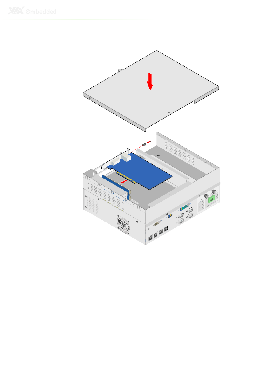
Step 5
Step 5
Step 5Step 5
Insert the PCI card and secure it with the screw.
43

Step 6
Step 6
Step 6Step 6
Install the riser layer case cover with five screws.
44

INSTALLING THE CD DRIVE (OPTIONAL)
Step 1
Step 1
Step 1Step 1
Remove the top cover CD drive and HDD casing by unscrewing
the six screws.
45

Step 2
Step 2
Step 2Step 2
Unscrew the four screws of CD drive bracket plate.
46

Step 3
Step 3
Step 3Step 3
Insert the CD drive into the bracket and secure it with four screws.
47

Step 4
Step 4
Step 4 Step 4
Secure the CD drive to the case.
Note:
Note:
Note: Note:
Make sure the drive’s cables are properly connected.
48

INSTALLING THE HARD DISK DRIVE IN
BOTTOM CASING
Step 1
Step 1
Step 1Step 1
Unscrew the four screws of the hard disk drive bracket then insert
the 2.5 hard disk drive. Secure the hard disk with four screws.
(O
PTIONAL
)
49

Step 2
Step 2
Step 2Step 2
Secure the hard disk drive to the casing and connect all the
necessary hard disk drives cables.
Step 3
Step 3
Step 3Step 3
Install the top cover and secure it with six screws.
50

Step
Step 4444
Step Step
Connect the SATA port and power ports of the storage casing to
the SATA and power ports of the AMOS-1000. Then stack the
AMOS-1000 on top of the storage casing and secure the AMOS1000 to the storage casing with four screws.
Note:
Note:
Note: Note:
When disassembling the AMOS-1000 and storage casing, you
can easily disconnect the SATA port and power port of AMOS1000 and storage casing.
51

Step
Step 5555
Step Step
Replace the cover of AMOS-1000.
Step 6
Step 6
Step 6Step 6
Secure it with six screws.
52

INSTALLING THE AMOS-1000 WALL
BRACKET
Step 1
Step 1
Step 1Step 1
Install the left and right wall bracket to the bottom of AMOS-1000.
53

Step 2
Step 2
Step 2Step 2
Secure the four screws to install the AMOS-1000 on the wall.
54

A
Exploded Diagram
55
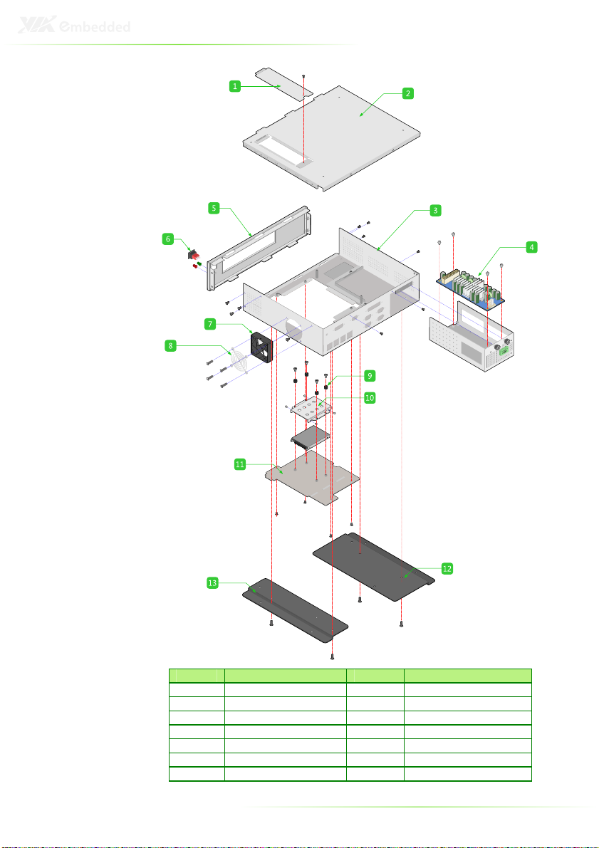
Item Parts list Item Parts list
1 PCI/PCI-E Cover 8 Fan Cover
2 Top Cover 9 HDD Damper
3 Bottom Chassis 10 HDD Bracket
4 Power Board 11 Bottom Cover
5 Front Bezel 12 Mounting Bracket Right
6 Power Switch 13 Mounting Bracket Left
7 System Fan
56

B
Compatible
Mini-ITX boards
57
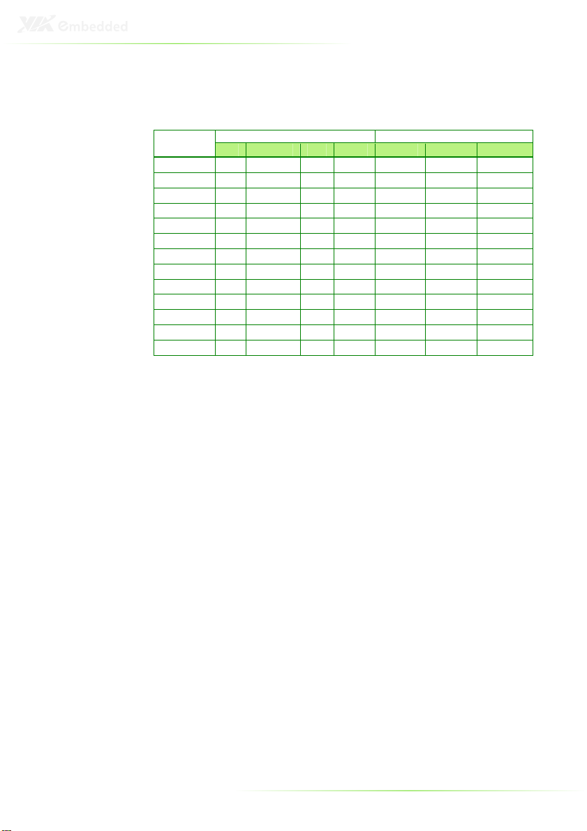
The AMOS-1000 supports a variety of VIA Mini-ITX boards as
shown below. Contact a local sales representative for detailed
information.
Model
EPIA-M700
EPIA-SN
EPIA-EX
EPIA-EK
EPIA-EN
EPIA-CN
EPIA-LT
EPIA-LN
VB8002
VB8001
VB7007
VB7002
VB7001
CF Mini-PCI PCI PCI-E LPC-01 LCP-02 PUSB-01
√ - √ - - - x
√ √ - √ √ √ x
- - √ - √ √ √
- - √ - - - √
- - √ - √ √ x
- - √ - - - x
- - √ - √ √ x
- - √ - √ √ √
- - √ - - - √
- √ - √ √ √ √
- - √ - - - √
- √ - √ √ √ √
- - √ - - - √
I/O Board Support
Slot
58

C
Cable Tie Location
Illustration
59

Location Cable Tie Purpose Location Cable Tie Purpose
Cable Tie Locations and Purpose
1 Fix Switch/LED Cable 9 Fix 3rd SATA HDD Cable
2 Fix SATA Power Cable 10 Fix Slim ODD SATA Cable
3 Fix 1st SATA HDD Cable 11
4 Fix 1st SATA HDD Cable 12 Fix Wireless LAN USB cable
5 Fix 1st SATA HDD Cable 13
6 Fix System Power Cable 14
7 Fix System Power Cable 15
8 Fix 2nd SATA HDD cable 16
Fix Storage Chassis Power
distribution cable
Fix Wireless LAN Antenna
cable
Fix PUSB-01, LPC-01, LPC-02
signal cable
Fix PUSB-01, LPC-01, LPC-02
signal cable
Fix PUSB-01, LPC-01, LPC-02
signal cable
Note:
Note:
Note: Note:
Cable Tie location 1 to 7 places to fix cable ties in AMOS-1000
chassis. Locations 8 to 16 are optional put in Accessory Box.
60
 Loading...