

Operators Manual
© E-max Gaming Corporation.
9900 Clinton Rd. Cleveland, Ohio 44144
Phone 216.961.3500 • Toll Free 800.321.0757
Part number: HH813
Revision 4
February, 2006
This manual should not be reproduced in any
manner without written consent from the E-max Gaming Corporation Inc.
E-max Gaming Corporation, Inc.

E-max Gaming Corporation, Inc.

Table of Contents
Introduction i.
CHAPTER 1
Getting Started 1.0
Unpacking 1.1
Contacting Service 1.2
CHAPTER 2
Installation 2.0
Console Installation 2.1
Console Devices 2.2
Basic Controls 2.3
Electrical Installation 2.4
Powering up the Console 2.5
Flashboard, Video and Audio
Installation 2.6
CHAPTER 3
Ball Handling 3.0
Handling and Calling Balls 3.1
Calling a Ball 3.2
Resetting a Ball 3.3
Ball Tray System Failure 3.4
Manual Mode 3.5
Calling a Ball in Manual Mode 3.6
Resetting a Ball in Manual Mode 3.7
Resetting the Flashboard in Manual Mode 3.8
CHAPTER 4
Console Security System 4.0
CHAPTER 5
Quick Tour 5.0
Tutorial 5.1
System Startup 5.2
Playing Bingo 5.3
Verifying a Winner 5.4
Using the Toolbar 5.5
E-max Gaming Corporation, Inc.
3

CHAPTER 6
System Programming 6.0
Creating and Editing a Bingo Session 6.1
Game Pattern Definitions 6.2
CHAPTER 7
Special Functions Wild Number Feature 7.0
Multimedia Functions 7.1
CHAPTER 8
Servicing & Cleaning 8.0
General Cleaning of your E-max Bingo System 8.1
Replacing the Graphics Panel Light 8.2
Replacing the Blower Air Filter 8.3
Replacing the Arm Rest 8.4
Cleaning the Ball Tray Chamber 8.5
CHAPTER 9
Troubleshooting & Diagnostics 9.0
UPS Status Indicators and Alarms 9.1
CHAPTER 10
Warranty Information
CHAPTER 11
System Utilities 11.0
Back up CD 11.1
Restore Lost Game Data 11.2
Configure the Operating System 11.3
Install Software Updates 11.4
Touch Screen Calibration 11.5
Set the date and time 11.6
Testing the Flashboards 11.7
Gaming Log 11.8
payout Report 11.9
Gaming Report 11.10
Ball Frequency Report 11.11
Hardware Settings 11.12
E-max Gaming Corporation, Inc.
4

APPENDIX A
Console Diagrams
Operator Console Block Diagram
Dell System Connectors for Video and Peripheral s
Video and Audio Connections Block Diagram
Peripheral Device Connections Block Diagram
AC Power Connections
Data Router Console Side Connections
Data Router Field Side Connectors
Data Router Field Connector Pin Definiti ons
RF Modulator Connectors
APPENDIX B
Specifications
APPENDIX C
Wiring Diagrams
AC Outlet
E-max Gaming Corporation, Inc.
5

E-max Gaming Corporation, Inc.
6

1.0 Getting Started
The E-maxTM Bingo Console was designed to have a distinctively attractive
appearance, using careful manufacturing and assembly techniques to insure
quality. The E-max
electronics console and a ball console. Each is packaged in a separate shipping
container. One system configuration uses two ball consoles with one electronic
console. In this case, you will receive three shipping containers. Each Ball
Console weighs approximately 165 pounds while the Electronics Console weighs
about 196 pounds.
TM
Bingo Console is modular in design comprising of an
Chapter
1
1.1 Unpacking Console
9 Inspect the shipping containers for possible signs of damage. If damage is detected, refer to the Damage
Action Process section (1.3) for procedures.
9 Use scissors or box cutter to cut the straps from the skid only, taking care not to cut the straps protecting the
console. With the help of at least one assistant, carefully slide the Ball Blower Section of the console from
the skid and place it on solid flooring. Cut the remaining four straps from the console and remove the
cardboard top.
9 Remove the foam packing inserts from inside the top and slide the cardboard tube up and off the console. A
minimum of two people are required to safely unpack the console. Never lift the Ball Blower section by the
arm rest or any part of the ball chamber or ball catcher assembly (lift only by the console top). With one
person lifting from each end of the console, raise the console up and out from the carton and foam inserts. Set
the unpacked Ball Blower section on solid flooring. Check that all casters are in place. Do not destroy or
discard carton or packing material until after final inspection and testing.
9 Next, carefully slide the Electronics cabinet carton from the skid. Cut the remaining four straps from the
carton and remove the cardboard top. Remove the foam packing inserts from inside the top and slide the
cardboard tube up and off the console. A minimum of two people are required to safely unpack the console.
Never lift the Electronics cabinet from the monitor arm or any part of the monitor. Ensure that all doors and
drawers are secure before lifting. With one person lifting from each end of the Electronics cabinet, raise the
console up and out from the carton and foam inserts. Set the unpacked electronics Cabinet section on solid
flooring. Check that all casters are in place. Do not destroy or discard carton or packing material until after
final inspection and testing.
9 Unpack the keyboard from the cardboard box. Place the keyboard on the electronics cabinet in front of the
touch screen monitor. Remove the mouse from the plastic bag and set next to the keyboard.
9 At this point, you should inspect the consoles for any obvious shipping damage. If any problems are found,
immediately contact your distributor for advice and refer to the Damage Action Process section (1.3) for
procedures.
E-max Gaming Corporation, Inc.
7
The following accessories should be found in the Ball Blower section of the console:
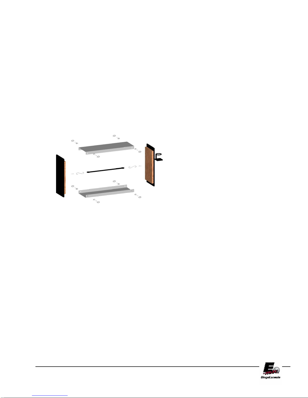
(1) Hardware Kit to join cabinets (two aluminum U channels and sixteen 5/16” – 18 x ¾” bolts
with washers) (Figure 1.1)
(1) Front Filler Panel
(1) Rear Filler Panel; with cup holder
(1) Rubber Bungee Cord
(1) Set of Bingo Balls
The following accessories should be found in the Electronic Cabinet of the console:
(1) Computer mouse
(1) Computer keyboard
(6) Keys for cabinet doors
(1) State configuration and application CD
(1) Recovery CD
(1) Blank CD for Backups
(1) Magnetic Reader Card
FIGURE 1.1
Hardware Kit to join cabinets (two
aluminum U channels, sixteen 5/16” – 18 x
¾” bolts with washers, bungee cord and two
filler strips)
1.2 Contacting Service
For Service information or technical assistance, contact the
E-max Technical Assistance Center 1-800-277-6214
1.3 Damage Action Process
Your E-max™ Bingo Console contains delicate electronic equipment. It is imperative that you thoroughly inspect the
contents of each package before accepting product delivery from the carrier.
In case of severe damage, refuse the equipment from the carrier. Contact your distributor for immediate replacement.
In case of damage, make a note on the bill of lading before accepting, take a photo of the damage, and keep the packaging to
aid in recovering the amount of claim against the carrier.
If the product is damaged but acceptable, take a photo before and after unpacking as a record of the damage and contact the
carrier’s agent immediately for inspection. Be sure to obtain a copy of the inspection report for your records.
If these precautions are not taken, we cannot assist you in recovering the amount of the claim against the carrier.
E-max Gaming Corporation, Inc.
8

2.0 Installation
Required Tools
1. 3/16 inch Allen wrench
2. ¼ Socket Driver (torque)
3. 5/16 Socket
4. Socket Extension 4”
Chapter
2
2.1 Console Installation
9 Roll both (or all three) cabinets into the approximate place they will be used.
Ideally you would like the console to be slightly elevated and centered in the hall. Position the two cabinets
as close together as you can with the Ball Blower on the side selected by the hall manager, or place the
electronics console in between the two ball consoles.
9 Slide the first aluminum U channel between the cabinets along the bottom. Use eight of the 5/16” – 18 x ¾”
bolts and washers to secure the bottom and sides of the two cabinets together (AT THIS POINT DO NOT
TIGHTEN BOLTS COMPLETELY WHICH WILL PREVENT PROPER U CHANNEL ALIGNMENT).
Next, install the top aluminum U channel using the same method described above. Next, Run the Ball tray
computer, USB and ball chamber power cables through the holes provided, into the Electronics cabinet.
(Refer to Section 2.4 for electrical installation procedures) Lastly, torque each bolt to between fifteen and
twenty foot pounds to secure U Channel’s in place.
9 Unlock the Electronics Cabinet drawer and open about one inch. Unlock and open the Graphics Panel door
on the Electronics cabinet. Using access provided by the graphics panel door, feed the three cables from the
Ball Blower Cabinet into the Electronics Cabinet. Insert the front Filler Panel between the cabinets in front of
the console (IF TWO BALL CONSOLES ARE PRESENT FEED SECOND GROUP OF THREE CABLES
FROM SECOND BALL CONSOLE INTO ELECTROICS CONSOLE). Attach the rubber bungee cord to
the eye hook. Next attach the other end of the rubber bungee cord to the rear Filler panel. (Note: Ensure
that the cup holder is facing up) (Figure 2.1)
9 Open the set of Atlas bingo balls. The E-max Gaming Corporation recommends ONLY Atlas bingo balls.
Atlas bingo balls are multi-colored and double numbered. Other balls may have been specified for your
system. Inspect each ball for damage and insert each ball into its corresponding slot in the ball tray to ensure
the set is complete. Any problems,
contact your distributor for a
replacement.
Figure 2.1
E-max Gaming Corporation, Inc.
9
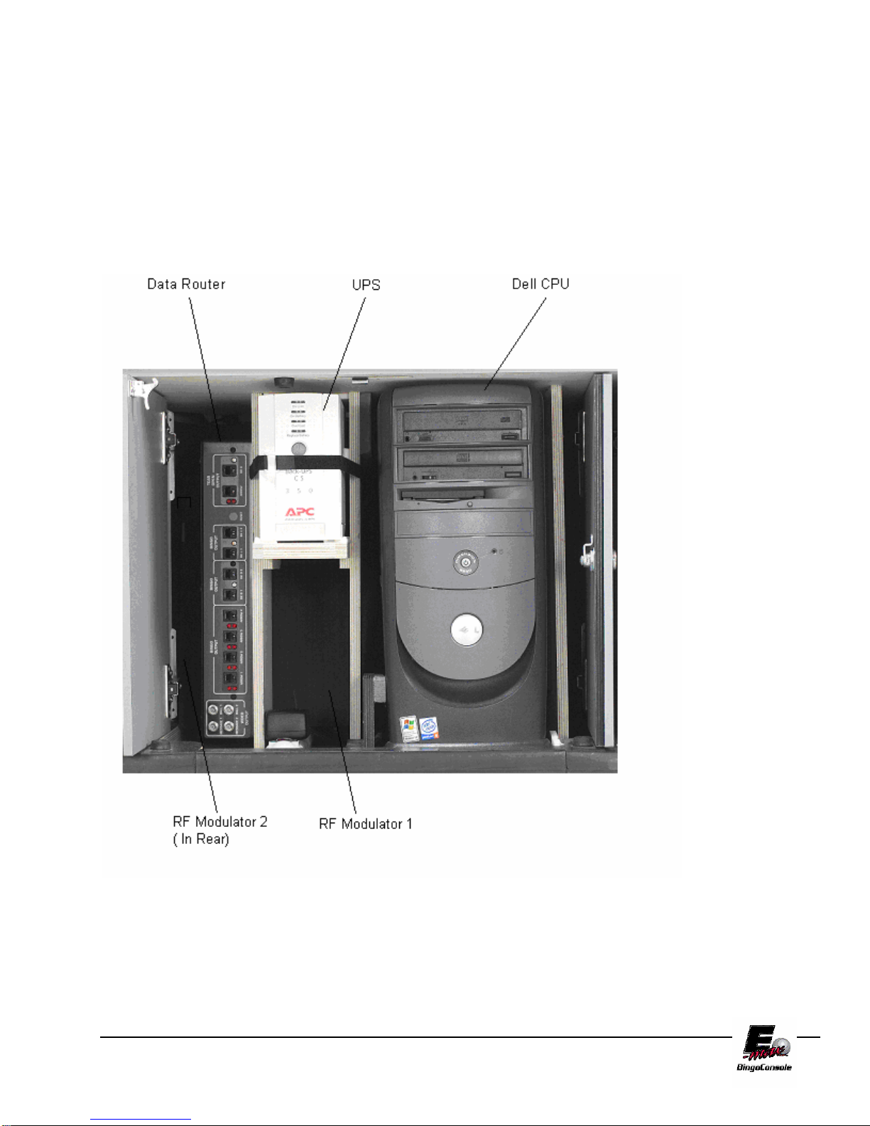
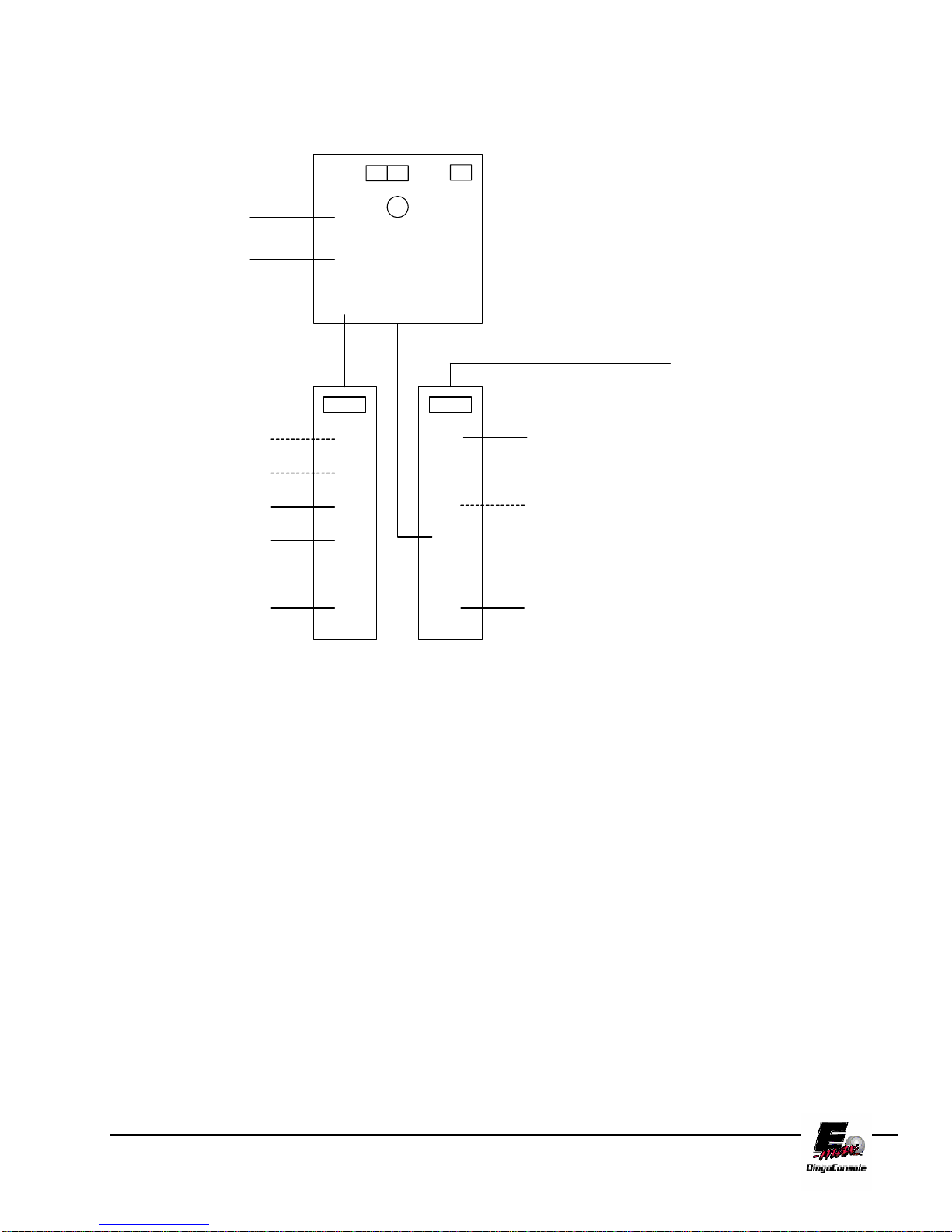
2.2 Console Devices
Electronics Cabinet Controls (Figure 2.2)
1. Dell CPU
2. UPS (Uninterruptible Power Supply) – Provides electrical power in the event of a primary power failure.
It contains the battery pack.
3. Data Router – This provides the external interface for flashboards and hall video.
4. RF Modulator 1 – For Ball Monitor
5. RF Modulator 2 – For Message Monitor
Figure 2.2
E-max Gaming Corporation, Inc.
10

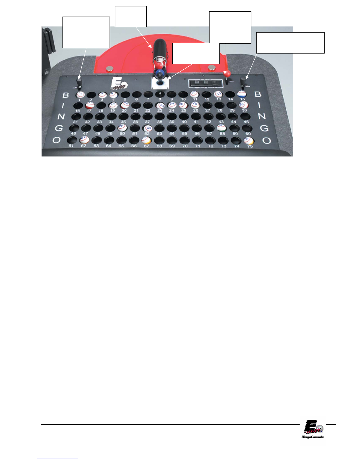
2.3 Basic Controls
Ball Blower Cabinet Manual Controls (Figure 2.3) & (Figure 2.4)
1. Blower Switch – This is the On/Off switch for the ball blower motor
2. Ball Reset Switch and LED – This switch cancels the last ball inserted into the ball tray. (only active in
Manual Mode when LED is ON)
3. Flashboard Reset Switch and LED – This switch clears all the called balls and flashboard. (only active in
Manual Mode when LED is ON)
4. Ball Tray Switches – Insert ball and press down on the ball to activate the switch.
5. Two black ball release knobs – Releases balls into ball tray chamber.
6. Red Door Release knob - Releases balls into mixer chamber.
7. Ball Camera with light – Embedded digital camera and white light ball illumination.
8. Ball Tube – Centers balls extracted from mixing chamber over camera.
Flashboard
reset switch
and LED
Ball reset
switch and
LED
Switch
Ball
Tray
switches
FIGURE 2.3
Blower
E-max Gaming Corporation, Inc.
11
Ball
Black Ball
Tube
Release
Knob
Ball Camera
Red Door
Release
Knob
Black Ball Release
Knob
with light
FIGURE 2.4
2.4 Electrical Installation
Refer to Appendix A for Diagrams
Connect three cables from the ball console to electronics console:
1. Plug ball console AC power cord into blower #1 socket on outlet strip #2
(Figure 2.5). If present, plug second ball console AC cord into blower #2 socket on outlet strip #2.
2. Plug in communications cable to the data router BT1 connector. Plug second communications cable into BT2.
3. Plug in camera cable into Dell computer USB5 connector. Plug in second camera into Dell USB1 connector.
NOTE: If you are installing a double blower configuration, you must configure the CPU for two ball chambers.
Refer to section 11.10 for hardware setting procedure.
CONNECT UPS TO POWER SOURCE:
The main AC power input to the E-max
cord to the E-max
circuit must be rated for at least 15A and no other hall equipment should share this power source. Do not run long
extension cords with inadequate wire gauge from the power source to the console.
CAUTION! A POWER SOURCE WITH ABNORMAL VOLTAGE OR EXCESSIVE NOISE CAN
RESULT IN IMPROPER CONSOLE OPERATION AND POSSIBLE DAMAGE NOT COVERED
UNDER WARRANTY.
1. Plug the cord from console Outlet Strip #2 (on the operator side of the electronics console) into the main
power source.
TM
Bingo Console should be wired with 12AWG or 14AWG with ground. The AC power input
TM
Bingo Console should be 115VAC, 60Hz. The power outlet or power
E-max Gaming Corporation, Inc.
12
E-MAX
AC POWER CONNECTIONS
UPS SOCKETS
1,2,3 ARE BACKUP
DELL
OPERATOR
DISPLAY
NETWORK DEVICE #1
NETWORK DEVICE #2
DON'T USE
FAN
DATA ROUTER
1
2
3
1
2
3
4
5
UPS
POWER
INPUT
4
5
6
1
2
3
4
5
UPS SOCKETS
4,5,6 ARE NON
BACKUP
DON'T USE
DON'T USE
DON'T USE
AC POWER IN
BLOWER #1
BLOWER #2
PRINTER OR VCR
RF MOD #1
LIGHT
OUTLET STRIP #1
(Graphics panel side)
6
6
OUTLET STRIP #2
(Operator side)
RF MOD #2
Figure 2.5
2.5 Powering up the Console
1. The main power “ON” switch for the electronic console is located on Outlet Strip #2 (Figure 2.5). After
turning on, press the button on the front of the UPS (Figure 2.6).
For maximum battery backup time allow the UPS to charge for a full eight hours prior to console
use.
E-max Gaming Corporation, Inc.
13

Figure 2.6
Observe that the following events occur after pressing and releasing the push-button:
• The green On Line indicator flashes.
• The yellow On Battery indicator lights while the Self-Test is being performed.
• When Self-Test has successfully completed, only the green On Line indicator will be lit and the Back-
UPS is ready for use.
WARNING!
If the internal battery is not connected properly, the green On Line indicator and red Replace Battery indicator
will light and the UPS will also emit a chirping sound. (Call for service if this occurs).
2. Once power is applied to the UPS, the red LEDs on the Flashboard Reset switch and the Ball Reset switch
should be blinking. This indicates the Dell computer is off and the system is waiting for Dell communications.
3. Turn on the Dell computer by pressing the power on button on the front of the computer. The system will
power up and a display will be seen on the monitor (Chapter 4). White lights on the camera ball illuminator
should be on. When the Dell computer communicates with the data router and the ball tray, the two red LEDs on
the manual switches will turn off.
4. Turn on the blower motor switch on the ball console. If the blower fails to start, check the blower motor
troubleshooting section (Chapter 9). If the motor is operational, turn it off. Release the balls into the ball tray
chamber by using two hands and pulling back on both black knobs. Now release the balls into the mixing
chamber by pulling back on the red door release knob and holding until all balls have entered the mixing
chamber.
2.6 Flashboard, Video and Audio Installation
The E-maxTM Bingo Console supports a wide variety of audio, video and flashboard systems. Each installation is
unique to your hall environment. Please refer to the E-max
how video, audio and flashboard systems interface to the E-max™. Your E-max™ distributor or factory
representative should be consulted and assist with these installations.
E-max Gaming Corporation, Inc.
TM
Bingo Console Installation Manual which describes
14

3.0 Ball Handling
3.1 Handling and Calling Balls
When the blower motor is turned on, the balls momentarily mix and then 4 to 6
balls will be extracted from the mixing chamber into the ball tube. The design of
the new console automatically insures that this first group of balls and all the
following balls are random in nature without the need of any special pre-mixing of
the balls.
The black plastic ball tube covering allows the audience to see the group of 4 to 6 balls but not pre-read the ball
numbers.
The first ball extracted will come to rest at the end of the ball tube and directly over the embedded camera. The
standard balls supplied with the console are double numbered. The camera views the bottom side of the ball and
the operator views the top side of the ball. To adjust the ball for proper viewing on the ball monitors do the
following:
1. Look at the ball, not the monitor
2. Simply rotate the ball with your fingers until the ball number is in the upright and straight position and is
readable.
3. The ball will automatically appear in the correct orientation for the monitors.
* NEW FEATURE *
Note that the E-max
Other systems require the operator to adjust the final position of the ball while viewing the monitor. The monitor
display is a mirrored image of the ball and it takes considerable operator training to be able to adjust the ball for
proper orientation. The E-max
intuitive manner.
TM
Bingo Console requires little training for the operator compared to other bingo systems.
TM
Bingo Console allows the operator to view and adjust the ball in a natural,
Chapter
3
3.2 Calling a Ball
1. To “call” the ball, remove the ball from the ball tube and insert the ball into its corresponding numbered
hole in the ball tray.
2. Momentarily depress the ball to activate the switch associated with that ball.
3. The new console will update the operator monitor, remote monitors, and flashboard accordingly.
NOTE: Depressing the ball and activating the switch again has no effect on the system for the remainder of that
game. When the system advances to the next game, the switch becomes active again.
NOTE: The E-max ball chamber uses a special antistatic mat and anti-static coated bingo balls. The anti-static
properties of the E-max Bingo Console are dependant on the use of these balls. It is recommended that only the
balls that are supplied with the E-max Bingo Console be used.
E-max Gaming Corporation, Inc.
15

3.3 Resetting the Ball
If the ball was inserted in the wrong hole then:
• Remove the ball from the hole
• On the operator monitor, touch the ball number of the wrong hole. This will reset the ball and the system
will be updated.
• Insert the ball in the proper hole and depress it to active the switch. The system is updated and correct.
3.4 Ball Tray System Failure
If the ball tray switches stop working, the ball should still be placed in its proper hole. The ball can be “called”
by touching the ball number on the operator monitor. The system will be properly updated.
3.5 Manual Mode
1. In the event of the Dell computer fails and the operator monitor is not operational, there is a system
Manual Mode that allows for only fundamental bingo operations.
2. The console is designed to automatically detect a Dell failure and switch to Manual Mode. This results in
the two red LEDs on the Flashboard Reset switch and Ball Reset switch to turn on. These two switches
now become active.
3.6 “Calling” a Ball in Manual Mode
1. To “call” the ball, remove the ball from the ball tube and insert the ball into its corresponding numbered
hole in the ball tray.
2. Momentarily depress the ball to activate the switch associated with that ball.
3. The Flashboard will be updated.
3.7 Resetting a Ball in Manual Mode
If the ball was inserted in the wrong hole then:
• Remove the ball from the hole
• Hold down the switch in the wrong hole and then momentarily depress the Ball Reset switch.
• Release the switch in the wrong hole.
3.8 Resetting the Flashboard in Manual Mode
To advance to the next game:
• Hold the Flashboard Reset switch down for at least 2 seconds until the flashboards clear.
• All of the individual ball switches are now active again for calling new balls. All previous ball
information is lost.
E-max Gaming Corporation, Inc.
16

4.0 Console Security System
Why is there security on the E-max™ console?
Regulatory agencies and hall owners are requiring more security and tracing of
system operations. Some of the items tracked by the E-max™ during gaming are:
1. Operator key stroke logs
2. Balls called and game patterns for each game
3. Winning cards for each game
4. Payouts for each game
5. Person running the console during gaming
Each of these reports can be printed or store them on a CD.
There are three levels of security on the new console system:
1. Console Operator
2. Organization/Hall Manager
3. System Administrator
Each operational feature available on the
console is assigned to one or more of these
levels. The System Administrator, with the
highest security clearance, has access to all
features, while the Game Operator has
access to a more limited set of features.
For some security levels, entire features or
screens are disabled and not even presented
to the user. In other cases, certain buttons
and selections on the screen are “grayed
out” or disabled.
For each user, the system stores:
1. Name
2. Password
3. Security level
4. An association of the user to one or
more organizations
The last item is required since a single console may be used by several organizations. The system security can
therefore be set up such that a given user is only allowed access to their related organization’s gaming schedules
and set ups.
There is a screen available for entry, editing, and removal of these four user items under “Utilities”. There is also
a security level associated with the entry of user data into the system:
1. There is only one System Administrator assigned to the console. The System Administrator can enter and
edit user data for multiple Organizations/Hall Mangers and Console Operators. They can also change the
Name and Password for the System Administrator. The System Administrator automatically is associated
with all organizations in the database.
2. Organization/Hall Manager can enter and edit user data for multiple Console Operators and also change
their own Name and Password.
Chapter
4
E-max Gaming Corporation, Inc.
17

3. A Console Operator cannot change their password without an Organization/Hall manger.
The system requires a user to “Log On” to the system before access is granted. Only one user can be logged on
the system at a time. Therefore, a current user must “Log Off” the system for a new user to take control of the
system.
To log on to the E-max Bingo Console:
1. Slide your user Magnetic card through the reader (future Upgrade) or
2. Enter your user password
a. With finger touch
b. With mouse curser and clicks on the video keypad
c. With the Dell keypad
3. Touch the ENTER button.
Note: The Magnetic Card included with your E-max Bingo Console is the “system Key”. You must not loose this
card! Keep the card in a safe place and protect it from damage. (Future Upgrade)
Initial Factory Security:
On a factory new console, a default name and password are entered into the database for a System Administrator.
The loaded information will be given to the proper personnel when installing the new console. The System
Administrator can log on the console to set up gaming and play games, however the system administrator must
enter user data for the Organization/Hall Mangers and Console Operators before they can use the console. An Emax™ service representative or authorized distributor can provide assistance in the set up.
When assigning passwords for a Console Operator, use an easy to remember number since many volunteer
operators may use their password infrequently.
Passwords are a minimum of 4 and a maximum of 10 numeric digits.
E-max Gaming Corporation, Inc.
18

5.0 Quick Tour
Quick Tour takes you through the steps required to play a simple bingo session. A
preloaded bingo game called DEMO has been installed to help you simulate an
actual bingo game. This quick tour will show you:
How to select a bingo schedule
Playing a bingo game
Verifying a winner
How to change game parameters using the toolbar
How to cycle through sessions
5.1 Tutorial
NOTE:
To create your own
sessions see
Chapter 6
Chapter
5
5.2 System Start Up
To start the quick tour program you
must first apply power to the console.
The system will take a few moments
to boot up which will bring you to the
Login screen (Figure 5.0) Slide your
magnetic card through the card
reader(future upgrade) or Enter your
pin number and touch the ENTER
button. The Main Menu Screen will
appear. From this screen touch the
PLAY BINGO button. (Figure 5.1)
NOTE: Use the factory supplied
password 13629 when starting a new
console.
Figure 5.0
E-max Gaming Corporation, Inc.
19
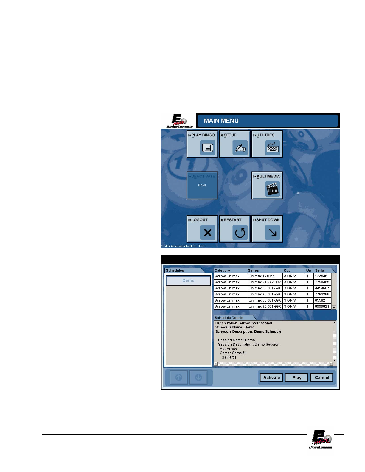
5.3 Playing Bingo
After touching the PLAY BINGO button the Choose Schedule screen will appear. (Figure 5.2) This screen
displays a list of preprogrammed schedules on the left, details about those schedules in the middle and serial
numbers (optional) on the right. To begin the tutorial, touch the Demo button on the left side of the screen and
then touch the Activate button. This will bring you back to the Main Menu Screen. Touch the Play Bingo
button. This will take you to LIVE GAME SCREEN
manager or system administrator before it can be played by a console operator.
. NOTE: A schedule must be activated by a
Figure 5.1
Figure 5.2
E-max Gaming Corporation, Inc.
20

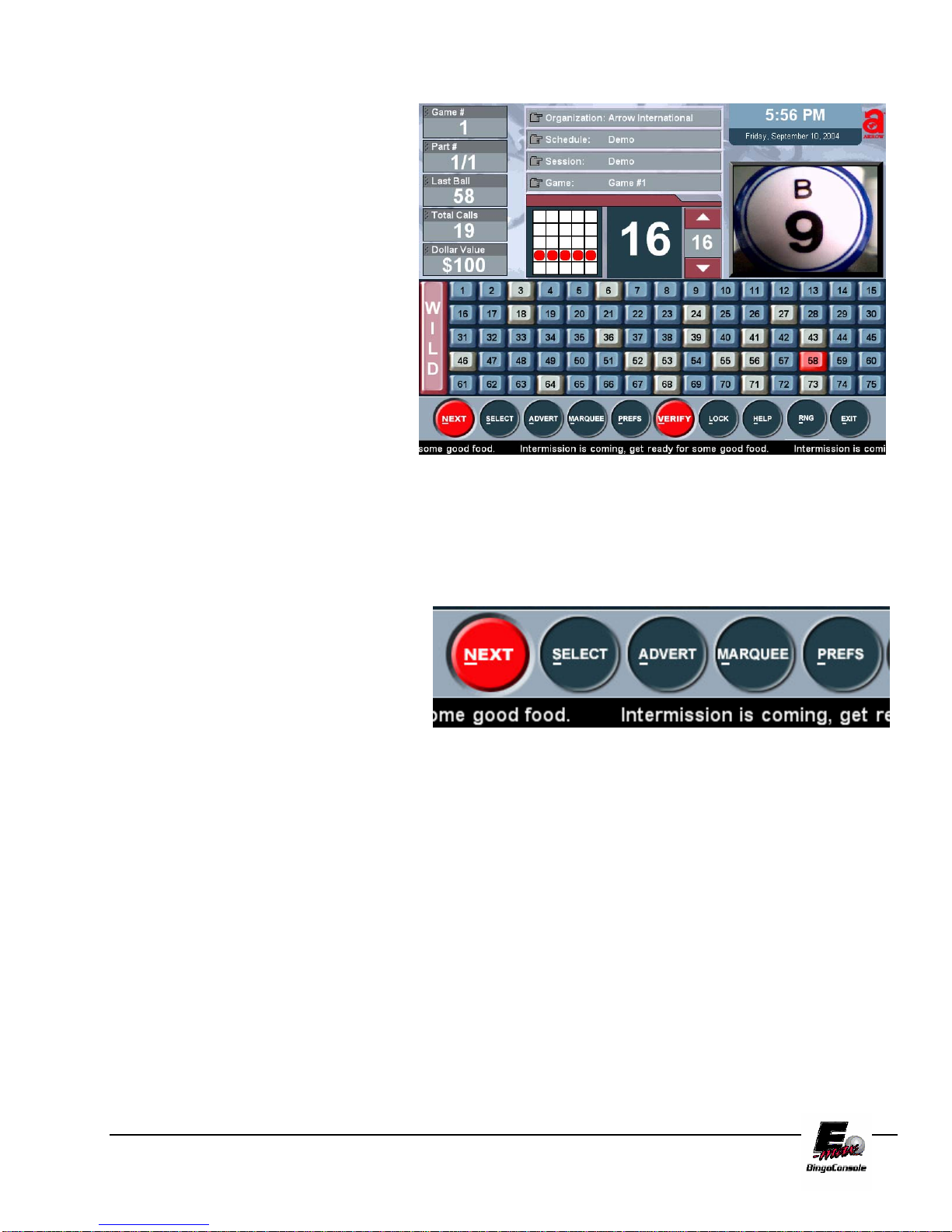
The Live Game Screen (Figure 5.3) is now displayed with the Demo Schedule as the preloaded session. There
are several items that make up this screen:
• Session / Game Info Upper left corner – The first line displays the Game # of the current Game, Next line
displays the Part # of the current Game, Next line displays the Last Ball called, then Total Calls in real
time for current game and the last line displays the Dollar Value for the current game.
• Clock Display – Displays the current time and date in the upper right corner.
• Flashboard Screen – Displays the same data output as the external flashboards.
• Ball Call Timer – Displays a timer that counts down the number of seconds between ball calls.
• Current Ball Status – Displays the number of calls, the last ball called and the ball activated timer count.
• Game Pattern – Displays the current game pattern being played.
• The Live Video Window – Is shown to help the caller place and align the last ball called in the center of
the hall monitor. When the game is set to the RNG mode a graphical representation of the last ball called
is shown. This window will also display an advertisement when selected from the advertisement screen.
• Marquee –The current marquee will be displayed scrolling at the bottom of the Game Screen. Marquees
can be attached when a session is built or they can be selected from the Marquee screen.
• Toolbar – The Live Game Screen Toolbar has buttons that can be selected during every bingo game.
Each of these selections will only affect the current game. Any permanent changes to the session’s
parameters should be programmed in SETUP located at the Main Menu screen. (See Chapter 6 System
Programming – Creating a Bingo Session)
E-max Gaming Corporation, Inc.
21
From this screen you may now play a
demo game. Turn on the Blower Power
Switch. You will see the game pattern for
the tutorial displayed on the Live Game
Screen. Start calling balls as you would
in a regular session. The ball timer will
reset to a preprogrammed limit and start
counting after each ball is placed into the
ball tray. The timer can be manually
adjusted during game play by using the
up/down arrow keys on the touch screen
or the up/down arrow keys on the
keyboard. The next step of the tutorial
will show you how to verify a winning
bingo.
Hot Key Feature
You will notice that each selection button in
the E-max™ toolbar has the first letter
underlined. The E-max™ features a “hot
key” function that allows the caller to select
options from the touchscreen or by pressing
the first letter of the option on the keyboard.
Figure 5.3
E-max Gaming Corporation, Inc.
22

5.4 Verifying a Winner
To verify a winner, touch the VERIFY button located on the
toolbar. This will bring up the Enter New Card (Figure
5.4) screen.
NOTE: (Optional AUTO SEARCH FEATURE) the
paper categories for the session being played will appear on
the top of the category list and will not have parenthesis
around them. If more than on category is programmed for a
bingo session the E-max™ will perform an auto search of
all the programmed categories in order to determine a valid
winner.
If you are playing a different category of paper from
the one that is programmed, you can choose a
Category on the left side of the screen to specify the perm
you wish to verify. Next enter the card number then touch
Enter.
The Verify / Payout screen is now displayed (Figure 5.5).
Winner (Figure 5.6) or Not a Winner will be displayed on
the lower left portion of the card with the last ball number
flashing. By touching the NEXT button you may enter in
another card number to verify. By touching the CHANGE
button you may change the dollar value for the selected
winning payout.
Touching the SAVE button will save the payouts and take you back to the Live Game Screen
for the current game. Touching the DONE button will save the payouts for the current game and take you to the
next game or next part of the current game. The CANCEL button will cancel any payouts you have input and
take you back to the Live Game Screen.
.
E-max Gaming Corporation, Inc.
23
Figure 5.4
Figure 5.5

The Verify/Payout screen allows you to quickly verify
winning cards for your bingo session. You can verify
multiple winners, calculate the payout and remove the
winning cards from progressive games.
The Serial number window on the right hand side of the
screen allows you to enter the serial numbers of the books
sold for your session. This adds another dimension to your
games security and integrity.
NOTE: If no valid winner is detected, the payout
screen will display the first card type with the entered
free space number.
Figure 5.6
E-max Gaming Corporation, Inc.
24
5.5 Using the Toolbar
The system Toolbar located at the bottom of the Live Game Screen allows you to change games,
advertisements, marquees and caller preferences. First, let’s navigate to a new game in this schedule.
Touching the NEXT on the toolbar will move you
forward to the next game or the next part of the
current game. The NEXT button will become
disabled when you reach the last part of the last
game in the schedule.
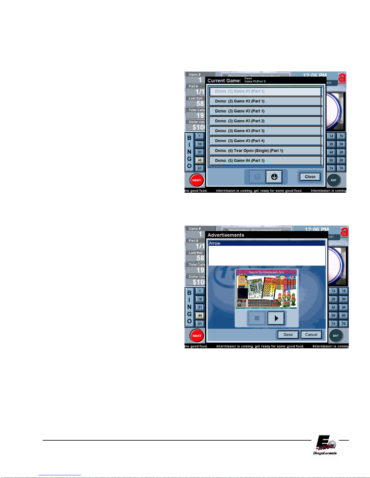
Touch the SELECT button on the Live Game
Screen. This will bring up the Game Selection
screen. This screen is a scrollable list of all the
games in the schedule. The current game being
played is displayed at the top of the screen. To
change the current game, scroll the game you wish
to play using the arrow buttons at the bottom of
the screen, and select the desired game from the
list. (Figure 5.7)
The ADVERT button brings up the
Advertisements screen where you can select an
advertisement to be played immediately. (Figure
5.8). The advertisement will be displayed on the
Live Video Window in real time when the SEND
button is touched. (To add advertisements see
Chapter 6 System Programming)
Figure 5.7
Figure 5.8
E-max Gaming Corporation, Inc.
25

The MARQUEE button brings up the Marquee
Screen (Figure 5.9). From the Marquee Screen,
you can select an existing marquee, add a new
marquee, edit an existing marquee or delete a
marquee.
Existing messages are shown in the list at the top of
the screen. The lower list is the list of marquee
messages that are currently playing. To play a
message, select it from the existing message list and
touch the down arrow to move it to the currently
playing list.
You do have the option of adding multiply marquees
to the Live Video Window by simply adding as
many as you like to the currently playing list.
Figure 5.9
To stop a message that is currently playing, select the message in the currently playing list and touch the up arrow
to remove it.
Touching the OK button will accept any changes you have made. Messages added to the currently playing list
will start scrolling, and any removed from the list will be removed from the scrolling marquee.
To add a new marquee, touch the NEW button, and enter your new message on the Keyboard screen. Touch the
OK button to add the new marquee. To edit an existing marquee, touch the marquee you wish to edit. Next touch
the EDIT button which will bring up the Keyboard screen. You may edit your marquee then touch OK to save
your new marquee message. To delete a message, select it in the list, and touch the DELETE button.
The PREFS button brings up the Preferences (Figure
5.10) screen. Five choices are displayed on the right of
the screen. You can make changes to audio volume by
touching VOLUME, to the game itself by touching
CALLERS CHOICE; to the way external flashboards
are set up by touching FLASHBOARD; if you have a
double blower you can change which ball camera will
display by touching Camera Settings and you can
display an external video source on your hall monitors
by touching Video.
Figure 5.10
E-max Gaming Corporation, Inc.
26

The VOLUME page will allow the user to choose one of five speaker output volumes ranging from VERY
LOUD to MUTE.
The CALLERS CHOICE page allows you to change bingo options for the current game before the game starts.
Once the first ball has been called, the game options can not be changed. (These options are discussed in
chapter 6, System Programming)
The Flashboard page allows you to changed Flashboard output (Game Pattern Numeric and Dollar Value
Numeric) for the current game automatically by selecting them from the drop down list box and touching the OK
button (Figure 5.11).
You can also disable the flashboard for the current game by placing a check mark in the Disable Flashboard box.
Figure 5.11
The Camera settings button is used in a double blower configuration. This feature allows the caller to switch
between the bingo camera and the tear open camera. (Figure 5.12)
Figure 5.12
E-max Gaming Corporation, Inc.
27
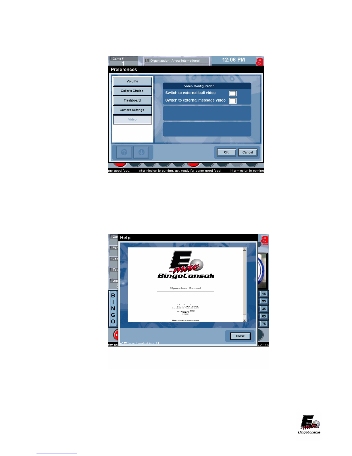
The VIDEO Screen (Figure 5.13) allows you to send an external video source (such as a DVD, VCR or Cable
TV) to the halls external monitors.
Figure 5.13
Touching the HELP button brings up the electronic copy of this manual (Figure 5.14). The manual is
hyperlinked and indexed for quick reference.
Figure 5.14
E-max Gaming Corporation, Inc.
28

6.0 System Programming
This chapter covers the E-maxTM Bingo Console programming and advanced
features.
6.1 Creating and Editing a
Bingo Session
To create bingo session(s) touch the SETUP button from the Main Menu
(Figure 6.0). The Organizations screen is displayed (Figure 6.1)
Figure 6.0 Figure 6.1
From the Organization Screen you can EDIT an existing organization (if present) or you can create a new
organization by touching the NEW button. This will display the keyboard screen. From the keyboard screen type
in a new organization name you wish to create by touchscreen or keyboard. (Figure 6.2)
Figure 6.2
Chapter
6
E-max Gaming Corporation, Inc.
29

The following demo session will explain the tabs and the settings in those tabs. In this demo session we will
examine the Arrow Organization and then step through each setting. Touch Arrow International in the
Organizations table. This will select Arrow International and fill in the default settings as shown in Figure 6.3.
In the Settings area of the organizations screen are several default settings that can be changed (Figure 6.3).
Touch the EDIT button to edit settings. Touch the SAVE button to save changes when finished.
The Verification drop down list box displays No Last Ball and Last Ball Required. This allows you to select
the verification method for all games in the organization. The Marquee scrolling speed can be adjusted from
slow to medium to fast.
The Number Parts box when enabled (check mark in box) will increment the session game #’s whenever a new
part is created. This feature allows the creation of progressive or multiple part games.
The RNG (Random Number Generator) feature must be installed by maintenance personnel before it can be
activated. This feature can be disabled (shaded out) from the Operator’s Console Playing Bingo screen by leaving
the selection box blank. Placing a check mark in the RNG box allows you to select Random Number Generator
during a bingo game from the Operator’s Console Screen.
The Caller’s Choice feature must be installed by maintenance personnel before it can be activated. When
selected (check mark in box), the Caller’s Choice option from PREFS (Preferences) menu on the Operator’s
Console Playing Bingo Screen will be enabled. To disable the Caller’s Choice option, un-check the Caller’s
Choice box.
To display the marquee in the Camera monitor place a check mark in the Show Marquee box by the Camera
Monitor. To turn off the marquee in the Camera Monitor uncheck the box. To show the marquee in the
Message Monitor place a check mark in the Show Marquee box by the Message Monitor. Uncheck the Show
Marquee box to turn off the marquee from displaying in the message monitor.
To display advertisements on the Message Monitor
select ADVERT
from the Message Monitor drop
down box. To display the flashboard on the
Message Monitor, select FLASHBOARD from the
Message Monitor drop down box.
Depending on the type of Flashboard you are using,
GAME PATTERN NUMERIC or DOLLAR
VALUE NUMERIC, you can change the output
values by selecting the drop down box of each. This
selection will output the selected value to your
flashboard if it supports the display value you
selected.
Figure 6.3
E-max Gaming Corporation, Inc.
30

To create a schedule(s) touch the Schedules tab.
The Schedules screen is now displayed (Figure
6.4).
To create a new schedule, touch the NEW button
and type in Arrow Schedule in the Schedule Name
Screen and touch the OK button.
To select the previously loaded Quick Tour session
Demo, touch it then touch the right arrow button
and touch SAVE. This will move the Demo session
to the available sessions for Arrow International
Organization (Figure 6.5).
To edit and or create new sessions touch the
Sessions tab (Figure 6.6). This will display the
Sessions screen. In the sessions screen you can
create a new session, edit an existing session or
delete a session.
Figure 6.4
Figure 6.5
Figure 6.6
E-max Gaming Corporation, Inc.
31

Under the Sessions screen on the left displays your selected organization and all available sessions associated
with that organization. The Quick Tour Demo is displayed in (Figure 6.6) with previously loaded settings.
To create a new session, touch the NEW button.
The SESSION NAME screen now appears. Next,
type “Saturday Afternoon” in the SESSION
NAME field. Since all new sessions MUST have
an activity associated with it, type in Early Birds
in the Activity field. This will create a new
activity called Activity1 with default settings
shown in (Figure 6.6). Use the drop down box at
the right of the Advert and Marquee to add an
Advert or Marquee to Activity1. Since all new
activities are by default Game activities, the
Game checkbox is selected. Touch the SAVE
button at the bottom of the Sessions Screen to save
Saturday Afternoon (Figure 6.7).
Figure 6.7
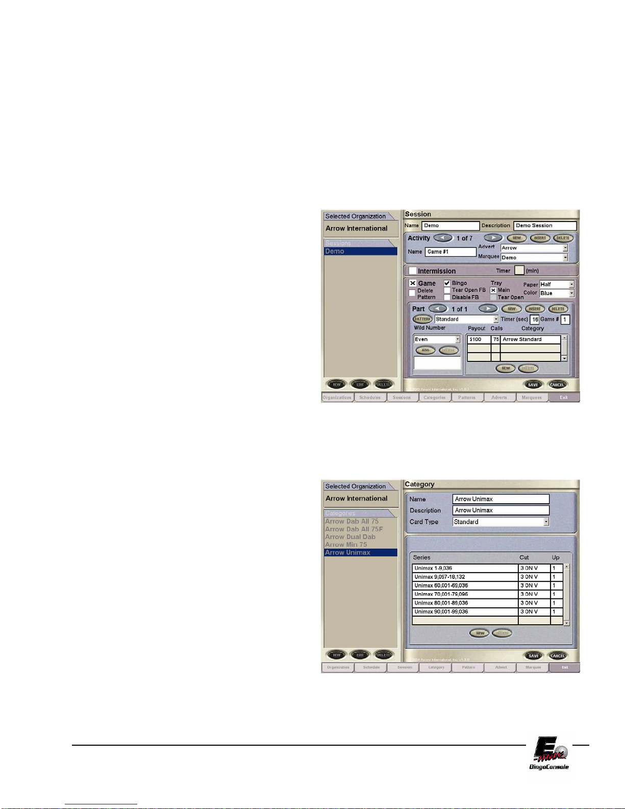
We will now step through and edit the Saturday
Afternoon session. Touch the EDIT button to edit
Saturday Afternoon session Activity1 game settings
(Figure 6.8). Currently, Saturday Afternoon has one
activity called Early Birds, to create additional
activities for Saturday Afternoon session select the
NEW button in the Activity panel. This allows you
to add new activities in sequence. To insert a new
Activity, touch the INSERT button, this will insert
an activity before your active activity shown. To
delete the currently selected activity, touch the
DELETE button to delete the current activity. To
change the activity from a Game to an
Intermission, place an X in Intermission box. A
Timer box (in minutes) allows you to define the
amount of minutes the intermission will run for.
Figure 6.8
For Activity1 the Game panel area has several settings that we will cover now. The Delete Pattern check box
when checked enables you to play delete
pattern games on the console. The Bingo and Tear Open checkbox’s enables you to select the output of that
game to a Bingo Flashboard or Tear Open or even both.
The Tray checkbox’s, Main and Tear Open, are enabled only when you are using multiple ball trays. If you
have a configuration of two ball tray’s attached to your electronic console, the Main and Tear Open checkbox’s
enables you to select which ball tray you will be using for your selected game. The Tray’s Main and Tear Open
selection also affect what camera will be operational for that game.
The Paper drop down box contains selections on how the cards will be displayed out to the monitor.
The Color drop down box will define color of face cards that you will be using for the selected activity.
The Pattern drop down box will define the pattern that you will be using for the selected activity.
E-max Gaming Corporation, Inc.
32
NOTE: To see the pattern as it will appear on the flashboard, touch the Pattern Button. When you are finished,
touch the Close button on the preview window.
The Part Panel displays the number of parts associated with the selected session. You may cycle through Parts
by touching the left and right arrow keys. To add a new part, touch the NEW button.
To insert a new Part touch the INSERT button, this will insert a part in between your selected Part showing. To
delete a Part touch the DELETE button, this will delete the select Part showing on the screen. To select a
different pattern for a selected Part touch the Pattern drop down list box and select it from the list. Touch the
pattern Button to preview the selected pattern.
To select a different time for the Ball Timer touch
the number in the Timer (Sec) box which will bring
up the Ball Timer keypad where you can enter the
new time and touch the OK button to save it.
To select a different Game # (Play Number) for a
particular Part touch the Game number and enter in
the new Play Number and touch OK to save.
The Wild Number can be changed for a particular
Part by selecting the drop down list box under Wild
Number. Touch the ADD to add more than one
Wild Number to a Part. Touch the DELETE
button to delete the selected Wild Number for the
selected Part.
To add more payouts for a particular Part touch the NEW button at the bottom of the payout
Figure 6.9
section and enter in new Value Payout number then touch OK. To delete a payout touch the
payout category you wish to delete then touch the DELETE button.
The Categories tab (Figure 6.10) defines the card
types; series; cuts and ups associated with them. To
add a new category touch the Categories tab. The
categories tab list the categories on the left then
name, description and the card type for that selected
category.
To change the Card Type for a selected category,
touch the EDIT button and then touch the Card
Type Arrow key. The different card types will
appear in a drop down menu. Select the card type by
touching it. The series window will clear and allow
you to add the desired series. Touch the New button,
Touch OK, touch the desired slot located in the
series window. This will bring up a drop down
menu that lists the card type and series available.
Touch the desired card type and series to select it. Next, touch the cut window to select the
cut of your bingo paper. Now you can touch the up window to select the number of sheets
in your paper package.
Figure 6.10
E-max Gaming Corporation, Inc.
33
These new features allow for even more security and integrity to your players gaming experience. To save
category and card type selections touch the SAVE button at the bottom right of the categories window.
To create a new Category, touch the New button. This will bring up the Keyboard screen. Type in the name of
your new category and touch the OK button. After you have named your new category
To delete a category select the category you wish to delete from the categories list on the left then touch the
DELETE button.
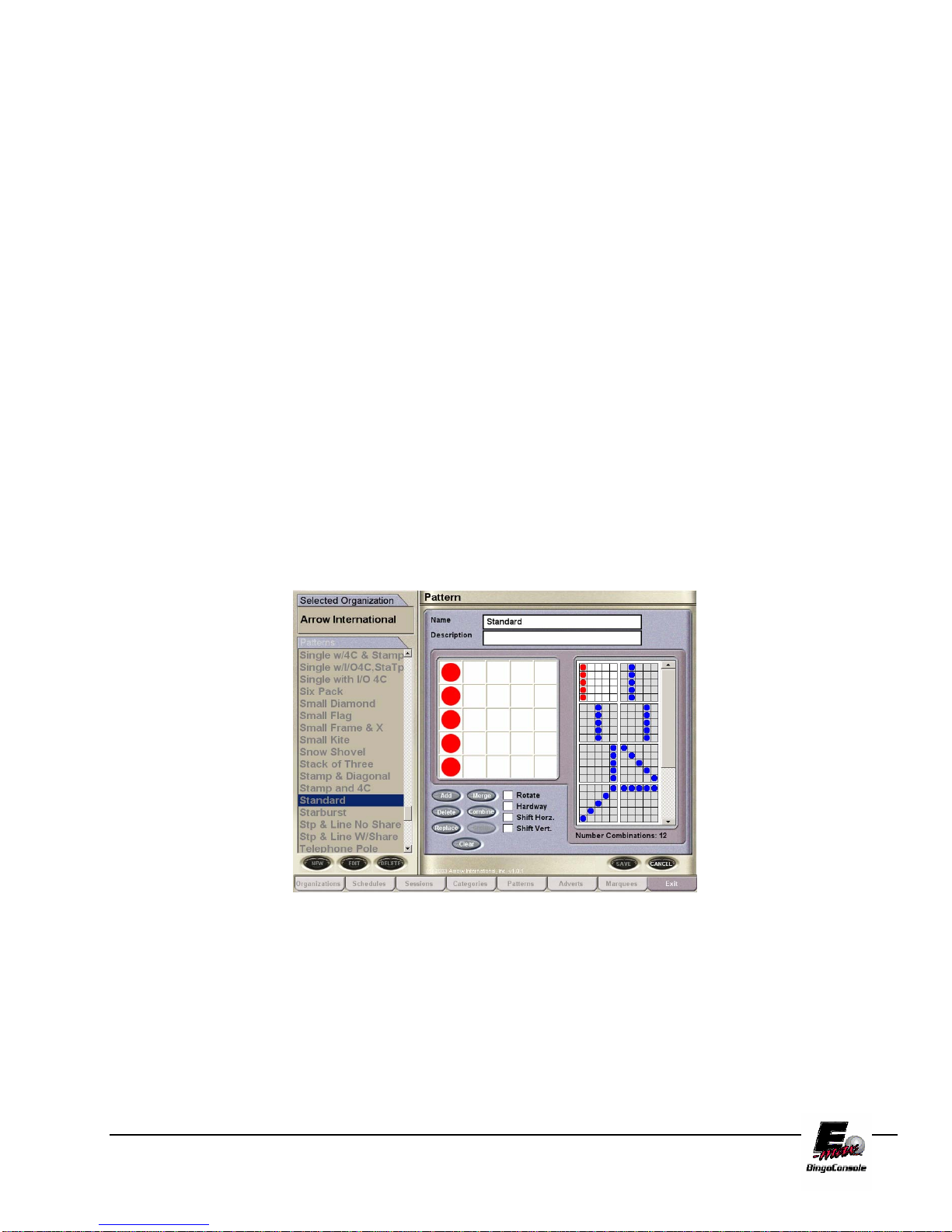
6.2 Game Pattern Definitions
The Pattern Screen in (Figure 6.11) allows you to define pattern types. A catalog list of patterns is displayed on
the left of the screen. The name of the highlighted pattern and its description is displayed in the Name and
Description fields. The pattern itself is shown in the pattern area below the name and description fields. The
Number of Combinations for the selected pattern will be displayed to the right of the selected pattern area. In
Figure 6.11 the pattern (Standard) is displayed with its 12 number of combinations.
Figure 6.11
E-max Gaming Corporation, Inc.
34

Touching – patterns are next
to but do not share any cells.
Any Line with Block of 4.
O
O
O
O O O
O O O
Overlap – must share two or
more cells between patterns.
Any Line with Block of 4.
O
O
O O
O O
O
Options:
Touch – True
Share – False
Overlap – False
Definition: Patterns must be next to but do not share any cells.
Touch – False
Share – True
Overlap – False
Definition: Patterns must share one and only one cell between patterns.
Touch – False
Share – False
Overlap – True
Definition: Patterns must share two or more cells between patterns.
Touch – True
Share – True
Overlap – False
Definition: Patterns that are next to but do not share any cells and patterns that share one and only one cell.
Touch – True
Share – False
Overlap – True
E-max Gaming Corporation, Inc.
Sharing – share one and only
one cell between patterns.
Any Line with Block of 4.
O
O
O
OO
OOO
Separate – have one or more
cells between patterns.
Any Line with Block of 4.
O
O
O
OO O
OO O
35

Definition: Patterns that are next to but do not share any cells and patterns that share two or more cells.
Touch – False
Share – True
Overlap – True
Definition: Patterns that share one or more cells.
Touch – False
Share – False
Overlap – False
Definition: Patterns with one or more cells are between patterns.
There are 214 preprogrammed patterns
included with your E-max™ Bingo Console.
You can use these patterns or create your own.
You can also combine any number of
programmed patterns to create multiple bingo
patterns.
Figure 6.12
E-max Gaming Corporation, Inc.
36

Special Functions
This chapter will take you through the steps to use the E-max™ System special
gaming features. In this chapter you will learn about:
Calling wild numbers
E-max Multimedia Functions
Chapter
7
7.0 Wild Number Feature
The following wild number options are available to select from:
• EVEN – All even numbers will be called.
• ODD – All odd numbers will be called.
• Trailing Number – Any number ending with that
number will be called.
• Leading Number – Any number beginning with that
number will be called.
• Day- All odd or all even numbers will be called based
on the calendar date.
• Double Reverse- Calls the reverse of the last number
called.
• Even/Odd Ball- Calls Odd or Even balls based on the
first ball called
1. Touch the SETUP button from the Main Menu.
2. Touch the desired Organization from the
Organization Screen.
3. Touch the Sessions tab.
4. Touch your desired Session from the list of available
sessions.
5. Touch the EDIT button.
6. Touch the Wild Number drop down list box from the
PART area.
7. Select the desired Wild Number and touch the ADD
button. This will place the selected Wild Number in the
Wild Number list box (see Figure 7.0)
Figure 7.0
E-max Gaming Corporation, Inc.
37

7.1 Multimedia Functions
The following options are available to select from:
• External Video- Provides switching for VCR/DVD.
Touch the Multi Media button from the Main Menu screen. This will bring up the Multimedia Options screen.
(Figure 7.1)
• Power Point – Runs Microsoft PowerPoint™
Presentations.
• Macro Media – Runs full Audio/Video Flash
Presentations.
Figure 7.1
E-max Gaming Corporation, Inc.
38

7.2 External Video
This section will take you through the steps to use the External Video feature. To Play Videos or DVD’s from an
external source you must first install the device. Refer to the appendix of this manual for installation information.
Once you have your player installed, follow the procedures listed below:
1. From the Multi Media Options Screen, touch the External Video button. This will bring up
External Video Window.
(Figure 7.2)
2. Select the monitor (monitors)
on which you wish to display
the video by touching the
check boxes and then the “ok”
button.
3. Press the play button on your
device.
NOTE: To stop the video, press the stop button on
your device and return to the External Video
window. Deselect the monitor outputs and touch
OK. This will return the video outputs to their
normal settings.
Figure 7.2
7.3 Power Point
Presentations
The E-max Bingo Console can run Microsoft®
Power point presentations in either .PPT or .PPS
files. To run a power point presentation; follow the
procedure below:
1. Insert your CD into the DVD (top)
drive of the Dell CPU.
2. From the Multi Media Options
Screen, touch the Power Point
button. This will bring up the
Power point window. (Figure 7.3)
NOTE: This may take several minutes depending on the size of the files.
E-max Gaming Corporation, Inc.
39
Figure 7.3

3. Select the presentation you wish to run from the list of files displayed in the window.
4. The Message Monitor is the default monitor for the presentation and cannot be changed. You can select
the camera monitor if you wish to use it.
5. Touch the Play button to start the power point presentation.
6. Touch the stop button to stop the presentation
7. To exit the power point window, touch the close button.
NOTE: Files with the .PPS extension will run as timed slide shows while files with .PPT extension can be run manually by
using the up and down arrow keys on the keyboard. At the end of the show, the Power Point options window reappears on
the callers monitor.
7.4 Macro Media
Presentations
The E-max Bingo Console can run macromedia®
Flash Media presentations in .SWF files. To run a
Macro Media presentation; follow the procedure
below:
Insert your CD into the DVD (top)
drive of the Dell CPU.
From the Multi Media Options Screen, touch the
Macro Media button. This will bring up the
Macromedia Flash window. (Figure 7.4)
NOTE: This may take several minutes depending on the size of the files.
1.
Select the presentation you wish to run from the list of files displayed in the window.
2. The Message Monitor is the default monitor for the presentation and cannot be turned off. You can select
the Camera Monitor if you wish to use it.
3. Touch the Play button to start the presentation
4. To stop the presentation, touch the stop button
5. To exit the macromedia flash window, touch the close button
NOTE: To exit the Multimedia Options screen; close the current window and touch the Main Menu button on the
Multimedia Options screen.
Figure 7.4
E-max Gaming Corporation, Inc.
40

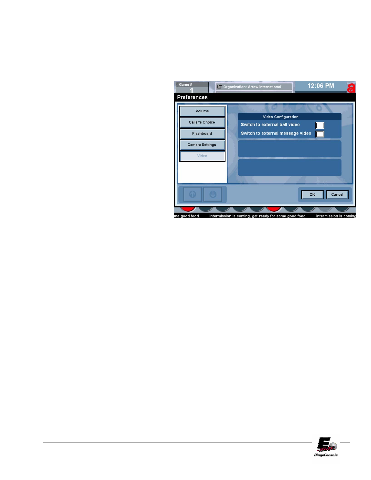
7.5 Playing Videos during a Session
The E-max Bingo Console can play videos/ DVD’s during an active gaming session. To do this; follow the
procedure below:
1. Insert your media (VHS tape/
DVD) into your player.
2. Press Play on your device
3. On the Live Game Screen,
touch the Prefs button. This
will bring up the caller
preferences screen. (figure
7.5)
4. Touch the video button. This
will bring up the video
configuration screen.
5. Select the monitors that you
wish to display the video on
by touching the appropriate
check box and then touch
OK.
NOTE: to stop the video you must press the stop button on your device and return to this screen and uncheck the monitors
then touch OK.
Figure 7.5
E-max Gaming Corporation, Inc.
41
7.6 Recording a Session
The E-max Bingo Console can record an active gaming session with the (optional) VCR installed. To do this;
follow the procedure below:
1. Insert your media (VHS tape
into your player).
2. Press REC on the VCR
3. Play your Session
4. To View the recorded
Session, go to the Live Game
Screen, touch the Prefs
button. This will bring up the
caller preferences screen.
(figure 7.6)
5. Touch the video button. This
will bring up the video
configuration screen.
6. Select the monitors that you
wish to display the video on
by touching the appropriate
check box and then touch OK.
NOTE: Your VCR is factory preset to work with the E-max™ Bingo Console. During shut down or power failure the
VCR may loose the setting memory. If this happens, set the VCR channel to channel 4 and set the video
input to LINE 1. Please refer to the owner’s manual of the VCR for further information about the
operation and care of the VCR.
CAUTION! THE CONSOLE SYSTEM MUST BE POWERED DOWN WITH THE UPS SWITCH
BEFORE SWITCHING OFF OUTLET STRIP #2. FAILURE TO SHUT THE UPS SYSTEM OFF FIRST
WILL RESULT IN INCOMPLETE UPS BATTERY DISCHARGE AND PREMATURE BATTERY
FAILURE NOT COVERED UNDER WARRANTY.
Figure 7.6
E-max Gaming Corporation, Inc.
42

8.0 Servicing and Cleaning
8.1 General Cleaning of Your E-
Chapter
8
max
Periodic servicing of your bingo equipment should include cleaning, polishing,
and light bulb replacement. Doing so will prolong the life of the equipment, increase trade in value, and reduce
breakdowns. Recommended cleaning agents and methods for the console and flashboard are as follows:
Monitor Touch Screen
Pour rubbing alcohol on a clean soft cloth and gently rub the screen to remove greasy finger prints. CAUTION:
Do not pour alcohol, water or any other liquid directly on the screen.
Console Painted Metal Surface
Use a mild soap solution or mild cleanser on a soft cloth. Harsh cleansers or solvents may damage the paint or
lettering. Follow with an automotive style polish for additional protection. CAUTION: Do not pour alcohol,
water or any other liquid directly on the surface.
Console Laminate Panels
Use a mild soap solution or Kitchen style cleaner on a soft cloth. Harsh cleaners or solvents may damage the
laminate surface.
Console and Flashboard Acrylic Surfaces
Use only a mild soap solution such as a liquid detergent solution on a clean soft cloth. Do not use solvents,
aromatic spirits, mild cleansers or paper towels since they may scratch the surface. CAUTION: Do not pour
alcohol, water or any other liquid directly on the surface.
Camera Lens
Use a vacuum cleaner to remove major dust and debris. Use a soft cloth to wipe lens.
Bingo Balls
Clean with a soft cloth and mild soap solution such as a liquid detergent and warm water (not hot water) or a
solution of 25% rubbing alcohol and 75% warm water. Harsh cleansers or solvents may damage the finish or
lettering. Dry the balls thoroughly using a cloth towel. Do not submerge the balls in liquids or use automatic
washing machines.
TM
Bingo Console
8.2 Replacing the Graphics Panel Lamp
HARZARD! Before replacing the light, turn off the switch on outlet strip #1.
The Graphics Panel fluorescent light is located just inside the electronic console above the graphics panel door.
Remove the Light fixture from the console and gently squeeze the diffuser lens to remove it from the fixture. The
fluorescent lamp should be replaced with the lamp specified in Appendix B.
E-max Gaming Corporation, Inc.
43

8.3 Replacing the Blower Air Filter
CAUTION! Insure that the ball console
power switch for the blower motor is in the
off position before servicing the filter.
The air filter is located in the Ball Console
behind the access panel (Figure 8.0) Unscrew
the two turn button screws on each side of the
access panel to remove the access panel. Slide
each air filter locking retainer away from the
filter then pull filter up to remove. Air filter
should be replaced with the filter specified in
Appendix B. Air filter replacement interval
varies depending on hall air conditions and
number of hours played. Check filter once a
month. A dirty filter can cause motor
overheating and poor ball action.
8.4 Replacing the Arm Rest
Figure 8.0
Call for Service to replace Arm Rest.
8.5 Cleaning Ball Tray Chamber
Call your authorized E-max™ distributor for all ball chamber maintenance
FOR ALL OTHER SERVICE NEEDS CONTACT YOUR LOCAL DISTRIBUTOR OR E-max™
REPRESENTATIVE.
E-max Gaming Corporation, Inc.
44

9.0 Troubleshooting and
Chapter
Diagnostics
HAZARD!
Note that when trouble shooting electrical systems, be aware of
the potential dangers of coming in contact with 120VAC line
voltages. Use caution when handling AC power cords and
devices. When feasible, during the trouble shooting procedure,
turn off the AC power input when handling these devices if you
are concerned with safety or call your service personnel for assistance.
When working with fuses or circuit breakers, call for service.
The trouble shooting guide is broken down into four main sections:
1. System Power
2. Electronics Console
3. Ball Console
4. Bingo System
Isolate your particular problem to one of these sections and then refer to that section for guidance.
9
E-max Gaming Corporation, Inc.
45
System Power Issues:
Problem Possible Cause What to do or check
Electronics and Ball
consoles have no power
Outlet strip #2 power cord
Hall power not available Check hall fuses or circuit
breakers
Plug cord into 120 VAC,
not plugged into hall power
grounded power source
or outlet switch not on
UPS power switch not ON Depress power ON switch
UPS circuit breaker tripped Depress UPS circuit breaker
button on the back of the
UPS
Power available, but
Electronics console
equipment not powered
Dell AC cord unplugged
from UPS
Plug in Dell power cord to
UPS1 socket as shown in
the Appendix
correctly
Dell computer turned off Depress power ON button
on Dell computer
Operator Monitor AC cord
unplugged from UPS
Plug in Operator Monitor
AC cord to UPS2 socket as
shown in the Appendix
Operator Monitor turned off Depress Monitor ON switch
on the front panel of the
monitor
AC Outlet Strip 1 not
plugged into UPS
Plug strip into UPS as
shown in the Appendix.
Note that strip 1 must go
into UPS3 socket.
AC Outlet Strip 1 or 2
circuit breaker tripped
Reset outlet power switch to
ON position
Power available, but Ball
console equipment not
powered correctly
Blower motor unplugged or
AC power cord to Ball
console not plugged into
Electronics console
blower motor circuit
breaker tripped
Plug in power cord to
Outlet strip #2 socket as
shown in the Appendix
Inside the blower motor
compartment, check that the
AC power cord is plugged
into the outlet. Reset the
breaker switch on the outlet
Blower motor switch OFF Place the switch on the ball
tray to the ON position
UPS did not work properly
when AC power failed
UPS defective or battery
pack worn or defective
Call for service to replace
the UPS
UPS is beeping Low AC line voltage Specification in Appendix
E-max Gaming Corporation, Inc.
46
Electronics Console Issues:
Problem Possible Cause What to do or check
Operator Monitor touch panel
not operating properly
Touch panel calibration Calibrate the touch panel
using Utilities provided
Touch panel defective Call for service
Touch panel cable unplugged Plug in cable to Dell and/or
Monitor as shown in
Appendix
Dell computer defective Call for service
Operator Monitor video image Monitor data cable unplugged Plug in cable to Dell and/or
Monitor as shown in
Appendix
Display defective Call for service
Dell computer defective Call for service
Operator Monitor audio Monitor audio cable
unplugged
Monitor speakers defective Call for service
Dell computer defective Call for service
Magnetic card reader Cable unplugged Plug in cable to Dell as shown
in Appendix
Defective reader Call for service
Dell computer defective Call for service
Data Router status LEDs not
on
Data Router AC adapter
Data Router software Depress the Data Router Reset
switch
Plug Adapter into Outlet 1 as
unplugged
shown in Appendix
Data Router fuse blown If the power ON LED is off,
check or replace the fuse
Defective AC adapter If the power ON LED is off,
and fuse is good, call for
service
Communications cable to Dell
unplugged
Plug in cable to the Data
Router and/or to Dell COM1
as shown in Appendix
Dell computer defective Call for service. In the
meantime, try Manual Mode
operations
E-max Gaming Corporation, Inc.
47

Electronics Console Issues (continued):
Problem Possible Cause What to do or check
Particular Data Router
flashboard LED and
associated flashboards not
working
Individual flashboard driver
fuse blown
Transfer flashboard cable to
an unused connector, if
available. If not available, call
for service
Dell computer not operating
properly
Program misoperating Exit the program and do an
orderly shutdown of the Dell.
Power the Dell OFF with its
power switch.
Shut off the UPS with the UPS
OFF switch. Power the UPS
back ON. Power the Dell back
ON. If still not operating
properly, call for service and
try Manual Mode operations.
Excessive noise on the AC
power line
Provide cleaner AC power to
the system
Corrupted hard drive Place Operating System CD
Disk #1 in CD drive and
restart Dell computer. Follow
instructions on screen loading
all Operating System CDs
then Applications CD and last
the Console Backup CD of
your database.
Dell computer defective Call for service.
Cooling fan not operating AC power unplugged Plug in power cord to Outlet
strip as shown in Appendix
Defective fan Call for service
Monitor arm Defective or broken Call for service
Light on graphics panel Blown bulb Replace bulb
AC power unplugged Plug in power cord to Outlet1
strip as shown in Appendix
Defective equipment Call for service
Mouse or keyboard Cable(s) unplugged Plug in cable(s) to Dell as
shown in Appendix
Defective equipment Call for service
E-max Gaming Corporation, Inc.
48
Electronics Console Issues (continued):
Problem Possible Cause What to do or check
Printer (optional equipment) AC power cord unplugged Plug in power cord to Outlet
strip as shown in Appendix
Communications cable
unplugged
Plug in cable to Dell and/or
Printer as shown in Appendix
Print quality, ink cartridge Replace cartridge
Defective equipment Call for service
VCR (optional equipment) AC power cord unplugged Plug in power cord to Outlet
strip as shown in Appendix
Video cable unplugged Plug in cable as shown in
Appendix
Defective equipment Call for service
Ball Console Issues:
Problem Possible Cause What to do or check
Blower motor No AC power, On/Off switch,
circuit breaker tripped
Check procedures under
System Power
troubleshooting
Poor bingo ball action Clogged blower air filter Replace filter
Low line voltage Specification in Appendix
Excessive static Make sure anti-static band is
installed in the bottom of the
ball chamber. If it is installed,
call for service
Lid on inner ball chamber
misaligned
Check for proper seating of the
lid and that ball extraction tube
is centered over blower hole
Defective blower motor Call for service
None of the ball tray switches
work
Communications cable
Data Router or Ball Tray
software
unplugged
Depress Reset switch on the
front of the Data Router
Plug in Ball Tray cable to Data
Router as shown in Appendix
Defective Ball Tray Call for service. In the
meantime, use the touch panel
on the Operator Monitor to call
and reset balls
Defective Data Router Call for service
One or a few of the ball tray
switches do not work
Defective Ball Tray Call for service. In the
meantime, use the touch panel
on the Operator Monitor to call
and reset balls
E-max Gaming Corporation, Inc.
49
No camera image, and no
camera white LEDs are on
Communications cable
unplugged
Plug in Camera cable to Dell
USB port as shown in
Appendix
Dell computer not turned on Depress Dell ON switch
Dell computer defective Call for service
Led board defective Call for service
Camera does not display ball
image on Operator Monitor
Camera lens is blocked by
Ball tube not centered over
Program is not on the main
Operator gaming screen
foreign material
camera
Use touch panel to display the
main Operating gaming screen
Remove material from the
camera lens area
Rotate the ball tube until it is
centered over the camera
Camera defective Call for service
Manual Mode switches do not
operate, switch LEDs are off
When the Dell computer is
normal, the switches are
System OK
disabled and LEDs are off.
Manual Mode switch(s) do not
Defective switch(s) Call for service.
operate when Manual Mode is
enabled and LEDs are on.
Defective Ball Tray Call for service.
Defective Data Router Call for service.
All bingo balls do not return to
Dirty ball tray chamber Call for service.
mixing chamber when the red
Door release knob is used
Ball Tray release (two black
knobs) do not return to their
normal position after releasing
Improper ball tray return
spring tension or dirt
accumulation
Call for service.
balls into the ball tray chamber
Depressing the bingo ball on
the ball tray switch works the
first time, but not the second
During a given game, the
system disables all repeat
actuations of a ball tray switch
System OK. The switch will
become active again on Next
Game.
time
E-max Gaming Corporation, Inc.
50

Bingo System Issues (as they relate to a Console problem):
Problem Possible Cause What to do or check
No video image on the hall
Ball Monitor or Message
Monitor
Video cable between the Dell
Video cable not plugged into
the console’s RF Modulator or
Data Router
video card an the RF
Check video cabling as shown
in the Appendix
Check video cabling as shown
in the Appendix
Modulator or Data Router or
VCR not plugged in
RF Modulator power cord
unplugged
Plug in power cord to the
Outlet strip as shown in the
Appendix
VCR turned OFF Turn on the VCR
VCR power cord unplugged Plug in power cord to the
Outlet strip as shown in the
Appendix
Defective RF modulator or
Call for service.
Data Router
Defective VCR Call for service.
Flashboards not operating Flashboard cable not plugged
into the Data Router
Check that cabling is plugged
into the correct RJ connector
on the Data Router as shown
in the Appendix
Data Router problem Check Data Router
troubleshooting procedures
shown above
Dell computer problem Check Dell troubleshooting
procedures shown above
Flashboard type not
Call for service.
compatible with new Console
Add on Electronic gaming unit
system does not work properly
Not certified by Arrow as
compatible
Call for service.
with new Console
E-max Gaming Corporation, Inc.
51

9.1 UPS Status Indicators and Alarms
There are four status indicators (lights) on the front of the UPS.
On Line (GREEN) – is lit whenever utility power is powering the
Battery Backup outlets.
On Battery (YELLOW)
powering equipment connected to the Battery Backup
Outlets.
Four Beeps Every 30 Seconds – this alarm is sounded
whenever the UPS is running on Battery. There is approximately 10 minutes of run time on batteries.
Suggest waiting 1-2 minutes in case the main power is restored then start shutting the Dell computer
down in an orderly manner.
– is lit whenever the battery of the UPS is
Continuous Beeping – this alarm is sounded whenever a low battery condition is reached. Battery run-
time is very low. The Dell must be entirely shut down by this time.
Overload (RED)
Continuous Tone – this alarm is sounded whenever the Battery Backup outlets are overloaded.
Circuit Breaker – the circuit breaker button located on the rear panel of the UPS will stick out if an
overload condition forces the UPS to disconnect itself from utility power. Reset the circuit breaker by
pushing the button inward.
Replace Battery (RED) – is lit whenever the battery is near the end of its useful life, or if the battery is
not connected. A battery that is near end of its useful life has insufficient runtime and should be
replaced. (CALL FOR SERVICE IF THIS OCCURS!)
Chirps for 1 Minute Every 5 Hours – this alarm is sounded whenever the battery has failed the
automatic diagnostic test.
– is lit whenever power demand has exceeded the capacity of the UPS.
E-max Gaming Corporation, Inc.
52

Warranty Information
E-max™ BINGO EQUIPMENT LIMITED
WARRANTY
Set out below are the terms of the Limited Warranty made by Emax™ Gaming Corporation, Inc. (EGC) in connection with the sale
of the Capitol Bingo Equipment (the “Equipment”).
1. Limited Warranty
EGC warrants to the original purchaser ('Purchaser') that the
Equipment will, for a period of ONE (1) YEAR from the date of original purchase of any Equipment in
the 'E-max™' product line from an authorized EGC dealer, be free from manufacturing defects in
material and workmanship. Purchaser represents to EGC that no employee, agent, or representative of
EGC (or an EGC dealer) has made any representation or warranty regarding the Equipment except as
set out herein.
This Limited Warranty applies to normal commercial use and does not cover failures or damage which
(a) occurs in shipment; (b) are caused by products not supplied by EGC; or (c) result from accident,
misuse, abuse, neglect, mishandling, misapplication, alteration, set-up-adjustments or modifications.
This Limited Warranty also does not cover any damage resulting from failure to install the Equipment in
strict conformity with both local fire and building codes and regulations, or if the installation does not
comply with the installation instructions provided by EGC.
2. Disclaimer of Warranties
EGC MAKES NO WARRANTIES, EXPRESS OR IMPLIED (INCLUDING, WITHOUT LIMITATION,
MERCHANTABILITY, FITNESS FOR PARTICULAR PURPOSE, OR AGAINST INFRINGEMENT OF
ANY PATENT), EXCEPT AS EXPRESSLY PROVIDED HEREIN. THE EXPRESS WARRANTIES
PROVIDED HEREIN ARE IN LIEU OF AND EXCLUDE ALL OTHER WARRANTIES, GUARANTEES
OR REPRESENTATIONS, EXPRESS OR IMPLIED, WHETHER ARISING BY OPERATION OF LAW
OR OTHERWISE.
3. Limitation of Remedies
If the Equipment supplied does not conform to the Limited Warranty set out above, EGC will, at
its option, (a) repair or replace the Equipment, or part thereof, which is defective, or (b) refund
so much of the purchase price as Purchaser has paid for the defective equipment, less 1/24th of
the purchase price for each month between the date of the purchase from an authorized EGC
dealer and the date of the discovery of the defect, provided that written notice of the defect and
its nature is given to EGC as soon as practical after discovery of the defect, but in no event later
than 90 days from the date of the discovery of the defect.
4. Limitation of Liability
The remedy of repair, replacement, or refund of the purchase price is Purchaser's sole and
exclusive remedy and will satisfy all of EGC's liabilities, whether based on contract, negligence,
tort, product liability, strict liability or otherwise. IN NO EVENT WILL EGC BE LIABLE FOR
INCIDENTAL OR CONSEQUENTIAL DAMAGES, NOR WILL ITS LIABILITY IN CONNECTION WITH
ANY EQUIPMENT OR SERVICE SOLD (INCLUDING NONDELIVERY OR LATE DELIVERY
THEREOF) EXCEED THE SALE PRICE OF SUCH EQUIPMENT OR SERVICE.
10
Chapter
E-max Gaming Corporation, Inc.
53

5. Warranty Voided
Any obligations of EGC under this Limited Warranty will be deemed to have been satisfied if
anyone other than an authorized Capitol Bingo Equipment Dealer services the equipment.
6. Transfer of Limited Warranty
Purchaser may transfer its rights under this Limited Warranty, subject to the terms and conditions
hereof, to a buyer (“Buyer”) from Purchaser of the Equipment. Thereafter, the rights under this Limited
Warranty are not transferable.
For the transfer by Purchaser of the Limited Warranty to be effective, the following conditions must
have occurred no later than the 30th day following the date of resale to Buyer:
A. Purchaser must have complied with all requirements to make the Limited Warranty
effective as to Purchaser; and
B. The Equipment (as an entire unit and as purchased by Purchaser) must be transferred to
Buyer.
Upon an effective transfer of this Limited Warranty, Buyer will be considered to be 'Purchaser' for
paragraphs 1, 4 and 8 hereof.
7. Inspection
With respect to any claim that the Equipment is defective, EGC will be allowed a reasonable time to
inspect the Equipment, in place. If the Equipment is altered or removed before EGC has made such
inspection or waived its right to do so, the obligations of EGC under this Limited Warranty will be
deemed to have been satisfied.
8. Proof of Purchase
Notwithstanding anything to the contrary in this Limited Warranty, Purchaser must, upon The EGC's
request, submit proof of original purchase (satisfactory to EGC) of the Equipment. The Limited
Warranty set out above shall not apply to, nor cover, any Equipment for which Purchaser is unable,
upon the EGC's request, to supply such proof of purchase.
9. Limitation of Actions
Any legal action against the EGC for a default of its obligations under this Limited Warranty must be
commenced within two (2) years from the date the Equipment was sold by an authorized dealer of the
Equipment.
E-max Gaming Corporation, Inc.
54

10. How to Obtain Service
If a problem with this Equipment develops during or after the warranty period, proceed as follows:
A. Refer to your Operator's Manual and follow the Troubleshooting Table within the 'Service
Section'.
B. Contact the authorized Capitol Bingo Equipment Distributor from whom you purchased the
Equipment.
C. Contact the Capitol Bingo Equipment Service Manager at the most convenient phone number
listed below:
1 (800) 321-0757 outside Ohio, but within the U.S.A.
1 (800) 537-3479 within the State of Ohio
1 (216) 961-3500 within the 216 area code or outside the continental U.S.A.
1 (216) 961-3641 fax number in Cleveland, Ohio
1 (800) 387-7621 within Ontario
1 (519) 770-4621 outside Ontario, but within Canada
1 (905) 670-0324 fax number in Canada
SERVICE CALLS WHICH DO NOT INVOLVE DEFECTIVE MATERIALS OR WORKMANSHIP AS
DETERMINED BY EGC IN ITS SOLE DISCRETION ARE NOT COVERED. COSTS OF SUCH
SERVICE CALLS ARE THE RESPONSIBILITY OF THE PURCHASER.
EGC wants you to remain a satisfied customer. If a problem occurs that cannot be resolved to your
satisfaction, please contact us immediately, Phone one of the numbers listed above or write to:
E-max Gaming Corporation
C/o National Service Manager
9900 Clinton Road
Cleveland, Ohio 44144
Please be sure to include the name, model number, serial number, date of original purchase, and the
distributor from whom you purchased the Equipment, as well as any actions taken to correct the
problem.
E-max Gaming Corporation, Inc.
55

E-max Gaming Corporation, Inc.
56

Chapter
11
11.0 System Utilities
System Utilities takes you through the system administrator and maintenance operations of the E-max
Bingo Console. In this section you will learn how to:
Create a back up CD of user programming (sessions and games)
Restore lost game data
Configure the operating system
Install software updates
Calibrate the touch screen
Set the Date and Time
Print/save gaming logs
Flashboard lamp test
11.1 Back up CD
To Create a back up CD follow the procedure below and refer to figure 11.0
It is highly recommended that backup operations be performed after initial in stallation, making any changes to the game
program or after a software upgrade of the E-max™ operating system.
1. Power up the outlet strip
2. Power up the Back UPS
3. Power up the Dell CPU
4. Log in as the system administrator
5. select Utilities from the Main Menu
6. Open the CDRW drive and insert the Arrow Backup CD PN: HH815. (this is the bottom of the
two drives)
7. Touch the Backup button
8. The backup operation screen will appear
9. Touch the Backup button in the center of the screen
10. The time stamp window will appear and ask you if you wish to continue?
11. Touch yes
E-max Gaming Corporation, Inc.
57

12. The backup operation will run.
NOTE: This may take several
minutes
13. The Backup completed
successfully window will appear
when the backup operation is
complete.
14. Touch OK
15. You will be returned to the
Utilities screen
16. Remove CD from drive and store
in a safe place.
Figure 11.0
11.2 Restore lost game data
To restore the user programming, follow the procedure below and refer to figure 11.1
Restoration of user programming is needed
after a CPU change, operating system load or
other system failure that results in the game
information being lost.
1. Power up the outlet strip
2. Power up the Back UPS
3. Power up the Dell CPU
4. Log in as the system
administrator
5. select Utilities from the Main
Menu
6. Open the CDRW drive and
insert the Arrow Backup CD
PN: HH815. (this is the
bottom of the two drives)
7. Touch the restore button
8. The restore operation window
will appear
Figure 11.1
E-max Gaming Corporation, Inc.
58

9. Touch the refresh button
10. A list of the available backups will appear on the screen
11. Select the file you wish to use for the restore by touching the filename
12. Touch the Restore button
13. The restore operation will operation will run
14. When the restore is complete the Arrow Recovery window will appear
15. touch OK
16. This will take you back to the system login screen
17. remove the backup CD from the drive
11.3 Configure the operating system
To configure the E-max™ console for RNG or Caller’s Choice features, follow the procedure below and
refer to figure 11.3
Caution: Check with the local and state laws regarding caller’s choice and random
number generator before installing these features on the E-max™ Bingo Console
1. Power up the outlet strip
2. Power up the Back UPS
3. Power up the Dell CPU
4. Log in as the system administrator
5. select Utilities from the Main Menu
6. Open the CDRW drive and insert the Arrow configuration CD.
(this is the bottom of the two drives)
7. Touch the Upgrade Software button
8. The upgrade software operation window will appear Figure 11.3
9. Touch the refresh button
10. A list of the available software updates will appear on the screen
11. Select the file you wish to install by touching the filename
12. Touch the Install button
13. The install window will appear
14. Touch yes
15. The setup wizard window will appear after a few seconds.
16. Touch Next
17. The configuration options window will appear
18. select the options you wish to install by touching the check boxes
19. touch Next
20. touch Finish when the set up wizard window appears
21. When the configuration is complete the system will reboot and the security login screen will
appear
22. remove the configuration CD from the drive
E-max Gaming Corporation, Inc.
59
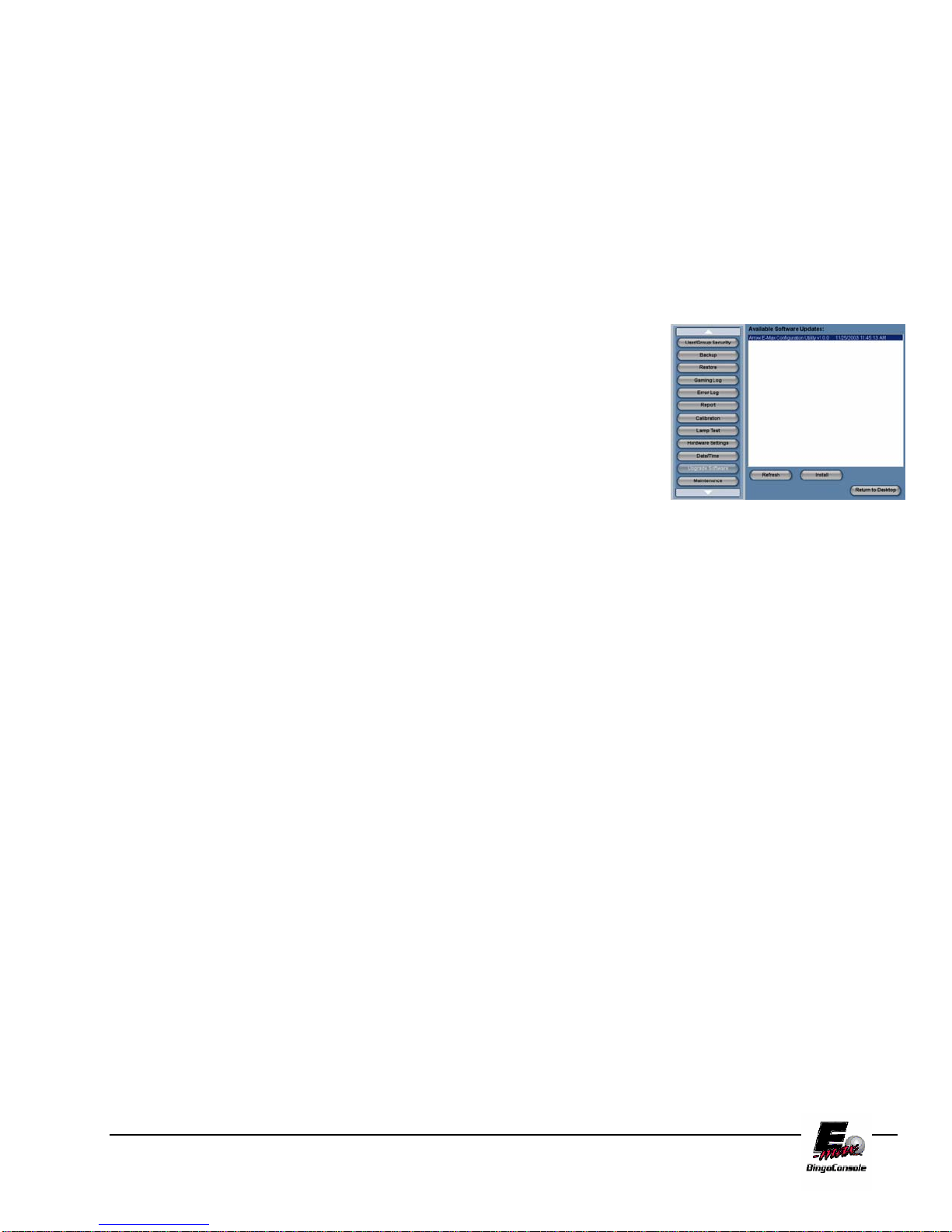
11.4 Install Software Updates
To update the E-max™ consoles operating system, follow the procedure below and refer to figure 11.4
Caution: Read the upgrade data sheet provided with the update CD carefully
before updating the OS on the E-max™ Bingo Console
1. Power up the outlet strip
2. Power up the Back UPS
3. Power up the Dell CPU
4. Log in as the system administrator
5. select Utilities from the Main Menu
6. Open the CDRW drive and insert the Arrow Update CD. (this is
the bottom of the two drives)
7. Touch the Upgrade Software button Figure 11.4
8. The upgrade software operation window will appear
9. Touch the refresh button
10. A list of the available software updates will appear on the screen
11. Select the file you wish to install by touching the filename
12. Touch the Install button
13. The install window will appear
14. Touch yes
15. The setup wizard window will appear after a few seconds.
16. Touch Next
17. The configuration options window will appear
18. select the options you wish to install by touching the check boxes
19. touch Next
20. touch Finish when the set up wizard window appears
21. When the configuration is complete the system will reboot and the security login screen will
appear
22. remove the configuration CD from the drive
E-max Gaming Corporation, Inc.
60
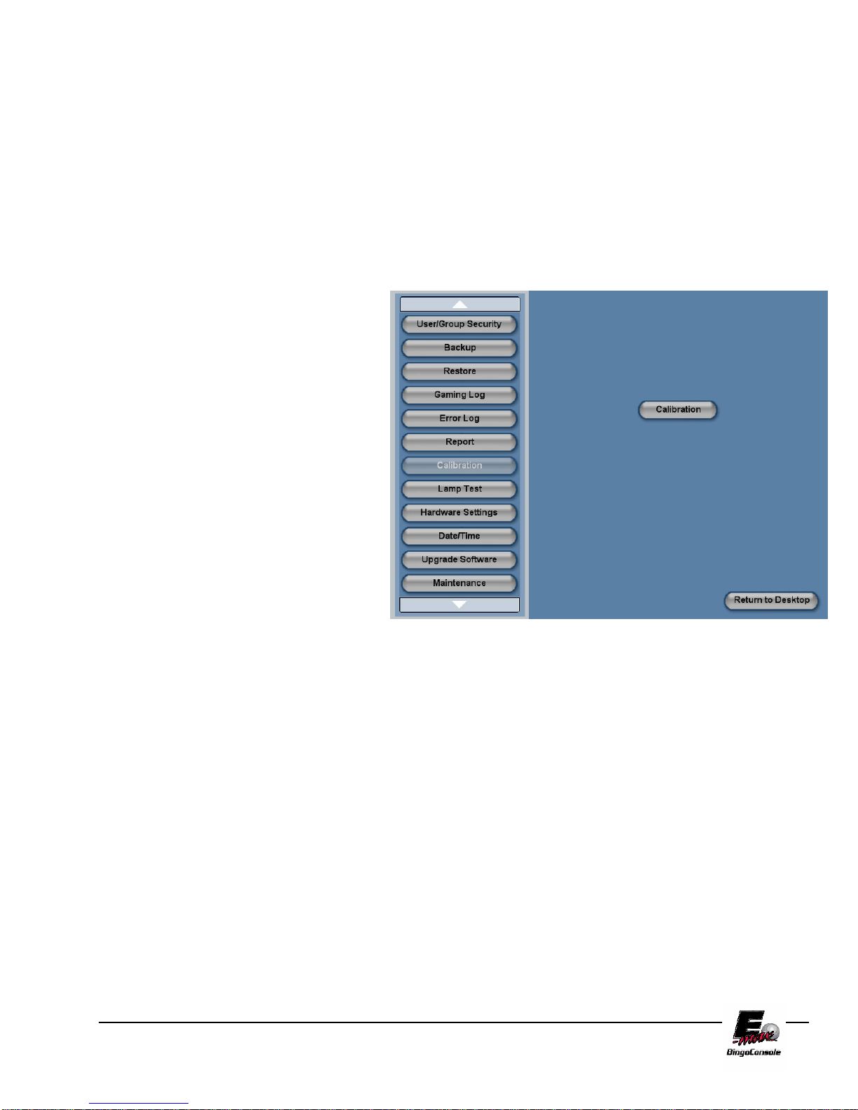
11.5 T ouch Screen Calibration
To calibrate the E-max™ touch screen, follow the procedure below and refer to figure 11.5
Caution: It is recommended that a small object (a pen tip) be used when calibrating
the touch screen. This will ensure the best possible control of the screen for the
console operator.
1. Power up the outlet strip
2. Power up the Back UPS
3. Power up the Dell CPU
4. Log in as the system
administrator
5. select Utilities from the Main
Menu
6. Touch the Calibration button
7. The calibration screen will
appear
8. Touch the Calibration button in
the center of the screen
9. The calibration screen will run
through 9 points on the screen
10. Touch each calibration point as it
appears on the screen
11. When all the points are finished
you will be returned to the
Utilities screen
Figure 11.5
E-max Gaming Corporation, Inc.
61

11.6 Setting the Date and Time
To set the E-max™ Date and Time, follow the procedure below and refer to figure 11.6
NOTE: The date and time are automatically updated from the CPU clock.
1. Power up the outlet strip
2. Power up the Back UPS
3. Power up the Dell CPU
4. Log in as the system administrator
5. select Utilities from the Main Menu
6. Touch the Date/Time button
7. The Date/Time settings screen will appear
8. Touch the Date drop down menu to adjust the date
9. Touch the Time (arrow up/Down) to adjust the time
10. Touch the time zone drop down menu the set the time zone
11. Select the check box to allow for daylight savings time
Figure 11.6
E-max Gaming Corporation, Inc.
62

11.7 T esting the Flashboards
To test the hall flashboards, follow the procedure below and refer to figure 11.7
NOTE: Lamp test is performed from the console utilities menu.
1. Power up the outlet strip
2. Power up the Back UPS
3. Power up the Dell CPU
4. Log into the system
5. select Utilities from the Main Menu
6. Touch the Lamp Test button
7. The lamp test screen will appear
8. Touch the Test button. (all flashboard lamps should turn on)
9. Touch the Reset button to turn the test off
Figure 11.7
E-max Gaming Corporation, Inc.
63

11.8 Gaming Log
The E-max Bingo Console keeps a gaming log of all operator actions during a session. To access these logs,
refer to the procedure below and figure 11.8
NOTE: If you are going to put these logs on a CD, please ensure that you have a
properly formatted, writable media disk in drive #2 of the Dell CPU.
1. Power up the outlet strip
2. Power up the Back UPS
3. Power up the Dell CPU
4. Log in as the system administrator
5. select Utilities from the Main Menu
6. touch the Gaming Log button
7. Touch the Schedule name drop down menu and select the session you want a log for
8. Touch the Date drop down menu to select the date you want a log for
9. Touch the Print button. (This will print out the log)
10. Touch the write to disk button if you want the log burned to a data CD
11. Touch the Delete button to delete the report
Figure 11.8
E-max Gaming Corporation, Inc.
64

11.9 Payout Report
The E-max™ Bingo Console keeps a gaming report of all games played, faces verified and winner payouts
during a session. To access this report, refer to the procedure below and figure 11.9
NOTE: If you are going to put these Reports on a CD, please ensure that you have
a properly formatted, writable media disk in drive #2 of the Dell CPU.
1. Power up the outlet strip
2. Power up the Back UPS
3. Power up the Dell CPU
4. Log in as the system administrator
5. select Utilities from the Main Menu
6. touch the Payout Report button
7. Touch the Schedule name drop down menu and select the session you want a report for
8. Touch the Date drop down menu to select the date you want a report for
9. Touch the Print button. (This will print out the report)
10. Touch the write to disk button if you want the report burned to a data CD
11. Touch the Delete button to delete the report
Figure 11.9
E-max Gaming Corporation, Inc.
65

11.10 Gaming Log
The E-max™ Bingo Console keeps a gaming report of all games played, faces verified, Ball Tray Activity
and winner payouts during a session. To access the Gaming Log, refer to the procedure below and figure
11.10
NOTE: If you are going to put these Reports on a CD, please ensure that you have
a properly formatted, writable media disk in drive #2 of the Dell CPU.
1. Power up the outlet strip
2. Power up the Back UPS
3. Power up the Dell CPU
4. Log in as the system administrator
5. select Utilities from the Main Menu
6. touch the Gaming Log button
7. Touch the Schedule name drop down menu and select the session you want a report for
8. Touch the Date drop down menu to select the date you want a report for
9. Touch the Print button. (This will print out the report)
10. Touch the write to disk button if you want the report burned to a data CD
11. Touch the Delete button to delete the report
Figure 11.10
E-max Gaming Corporation, Inc.
66
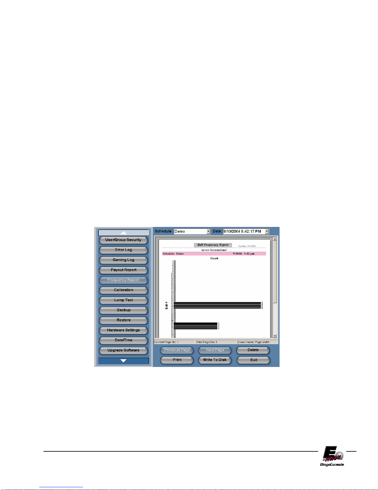
11.11 Ball frequency Report
The E-max™ Bingo Console keeps a gaming report of all games played, faces verified, Ball Tray Activity
and winner payouts during a session. To access the Ball Frequency Report, refer to the procedure below
and figure 11.11
NOTE: If you are going to put these Reports on a CD, please ensure that you have
a properly formatted, writable media disk in drive #2 of the Dell CPU.
1. Power up the outlet strip
2. Power up the Back UPS
3. Power up the Dell CPU
4. Log in as the system administrator
5. select Utilities from the Main Menu
6. touch the Frequency Report button
7. Touch the Schedule name drop down menu and select the session you want a report for
8. Touch the Date drop down menu to select the date you want a report for
9. Touch the Print button. (This will print out the report)
10. Touch the write to disk button if you want the report burned to a data CD
11. Touch the Delete button to delete the report
Figure 11.11
E-max Gaming Corporation, Inc.
67

11.12 Hardware Settings
The E-max™ Bingo Console can be installed as a single or double blower unit. If your installation is a
double, you must configure the Dell CPU to recognize the two ball cameras. Refer to the procedure below
and figure 11.12
1. Power up the outlet strip
2. Power up the Back UPS
3. Power up the Dell CPU
4. Log in as the system administrator
5. select Utilities from the Main Menu
6. Touch the Hardware Settings button
7. Touch the Double Blower setting
8. Touch the Save button
Figure 11.12
This Screen also displays the revision level and release date of the Data Router and the revision level of the
operating system.
E-max Gaming Corporation, Inc.
68

A
Console Diagrams
This Section contains diagrams to help you configure the Emax™ Bingo Console.
In this section there are diagrams for:
Operator Console Block Diagram
Dell System Connectors for Video and Peripherals
Video and Audio Connections Block Diagram
Peripheral Device Connections Block Diagram
AC Power Connections
Data Router Console Side Connections
Data Router Field Side Connectors
Data Router Field Connector Pin Definitions
RF Modulator Connectors
Operators Console Block Diagram
OPERATOR CONSOLE BLOCK DIAGRAM
Appendix
AC
LINE
UPS
AC-
bkup
AC
AC-
bkup
AC
AC
HP
PRINTER
PARALLEL
POWER
SUPPLY
BALL
CONSOLE 1
CAMERA
AC-
bkup
ADAPTER
USB 5
RJ45 2 PS2
MOUSE KEYBRD
BALL
TRAY
BALL
CDRW
DRIVE
CONSOLE 2
BALL
TRAY
DIAL-UP
MODEM
USB
2,3,4,6
CAMERA
USB 1
AC-
bkup
FLASH
BOARDS
Data
Router
COM 4
DELL COMPUTER
HARD
DRIVE
PS2 COM 5COM 1
AC
BALL
MONITOR
RF MOD
VIDEO1
MAIN VGA
LCD DISPLAY
15", 800x600
Data
Router
MESSAGE
MONITOR
RF MOD
VIDEO2
MAG
READER
ACAC
RJ45 1
AUDIO
AUDIO
OUT
TOUCH
PANEL
Data
Router
IN
E-max Gaming Corporation, Inc.
69

Dell System Connectors Peripherals Diagram GX270
DELL I/O
CONNECTIONS
COM 1
MAG CARD READER
PRINTER
PARALLEL
DO NOT USE
MOUSE
USB4
KEYBOARD
USB 1
TEAR OPEN
CAMERA 2
USB 5
MAIN
CAMERA 1
MIC IN
AUDIO
OUTPUT
VGA VIDEO
OPERATOR DISPLAY
USB 6
ETHERNET 1
DO NOT USE
VIDEO 2
MESSAGE MONITOR
VIDEO 1
BALL MONITOR
(USES PIGTAIL CABLE)
DO NOT USE
ETHERNET 2
COM 4
DATA ROUTER
MODEM LINE
UPS
C0M 5
TOUCH PANEL
MODEM PHONE
DO NOT USE
E-max Gaming Corporation, Inc.
70

Video and Audio Connections Block Diagram GX270
RF MOD 1
ANT IN
VIDEO
TV OUT
R
AUDIO
L
HH808
HH806
3.5MM
2 RCA
RF MOD 2
ANT IN
VIDEO
TV OUT
R
AUDIO
L
PANEL SIDE OF
NOTE:
F
F
BALL TV
OPTIONAL
VCR PLAYER
VIDEO IN
AUDIO
R
L
AUDIO OUT
F
F
MESSAGE
(GRAPHIC
CONSOLE)
ELECTRONIC OR
LINKED GAMING
VIDEO FEED
TO
IN
R
L
ANT IN
TV OUT
HH814
TO
TV
(NO VCR)
VIDEO OUT 1
SOUND CARD
SOUND CARD
SPKR OUTPUT
VIDEO OUT 2
VGA VIDEO
HH440
OPERATOR
DISPLAY &
E-MAX
VIDEO AND AUDIO CONNECTIONS
DATA ROUTERDELL
MIC INPUT
VGA TO VGA
SPKRS
HH807
RCA TO RCA
(3.5MM)
MIC INPUT
HH594
3.5MM TO 3.5MM
STEREO
HH807
RCA TO RCA
HH594
3.5MM TO 3.5MM
STEREO
VIDEO IN
BALL
AUDIO OUT
AUDIO IN
SOUND CARD
VIDEO IN
MESSAGE
AUDIO OUT
LCD MONITOR
VIDEO OUT
BALL 1
BALL
VIDEO OUT
BALL 2
VIDEO OUT
MESSAGE 2
VIDEO OUT
MESSAGE 1
AUDIO OUT
MESSAGE
IF BALL AND/OR MESSAGE MONITOR(S)
ARE COMPOSITE VIDEO, REMOVE THE
VIDEO AND AUDIO CABLES FROM THE RF
MOD AND CONNECT TO THE MONITOR(S)
HH808
BNC TO RCA
HH806
3.5MM STEREO
TO 2 RCA
BNC TO RCA
PA
TO
OR
PA
STEREO TO
HH808
BNC TO RCA
HH806
3.5MM STEREO
TO 2 RCA
F
F
OR
FEED
TO
PA
TV
FEED
F TO F
TV
E-max Gaming Corporation, Inc.
71

Dell System Connectors Peripherals Diagram GX280
E-max Gaming Corporation, Inc.
72

Peripheral Device Connections Block Diagram GX280
E-max Gaming Corporation, Inc.
73

Peripheral Device Connections Block Diagram GSX 270
E-MAX
PERIPHERAL DEVICE CONNECTIONS
DELL
WALL OUTLET
1
2
3
CABLE PROVIDED
WITH UPS
MODEM/PHONE/FAX
DATA
PORT
4
UPS
5
6
MODEM
LINE
GREEN PS2
PURPLE PS2
RED PARALLEL
COM 4
BLUE COM 1
USB5
USB1
ETHERNET #1
ETHERNET #2
MOUSE
KEYBOARD
PRINTER
HH545
HH444V0001
HH444
TOUCH PANELCOM 5
MAG READER
CAMERA #1 (FROM BLOWER #1)
CAMERA #2 (FROM BLOWER #2)
NETWORK DEVICE #1
DSL OR CABLE MODEM
OR NETWORK DEVICE #2
DATA ROUTER
HOST
HH438
BT1
BT2
BALL TRAY #1
(FROM BLOWER #1)
BALL TRAY #2
(FROM BLOWER #2)
HH514
HH514
HH512
HH512
E-max Gaming Corporation, Inc.
74

AC Power Connections
E-MAX
AC POWER CONNECTIONS
UPS SOCKETS
1,2,3 ARE BACKUP
DELL
OPERATOR
DISPLAY
NETWORK DEVICE #1
NETWORK DEVICE #2
DON'T USE
FAN
DATA ROUTER
1
2
3
1
2
3
4
5
UPS
POWER
INPUT
4
5
6
1
2
3
4
5
UPS SOCKETS
4,5,6 ARE NON
BACKUP
DON'T USE
DON'T USE
DON'T USE
AC POWER IN
BLOWER #1
BLOWER #2
PRINTER OR VCR
RF MOD #1
LIGHT
OUTLET STRIP #1
(Graphics panel side)
6
6
OUTLET STRIP #2
(Operator side)
RF MOD #2
E-max Gaming Corporation, Inc.
75
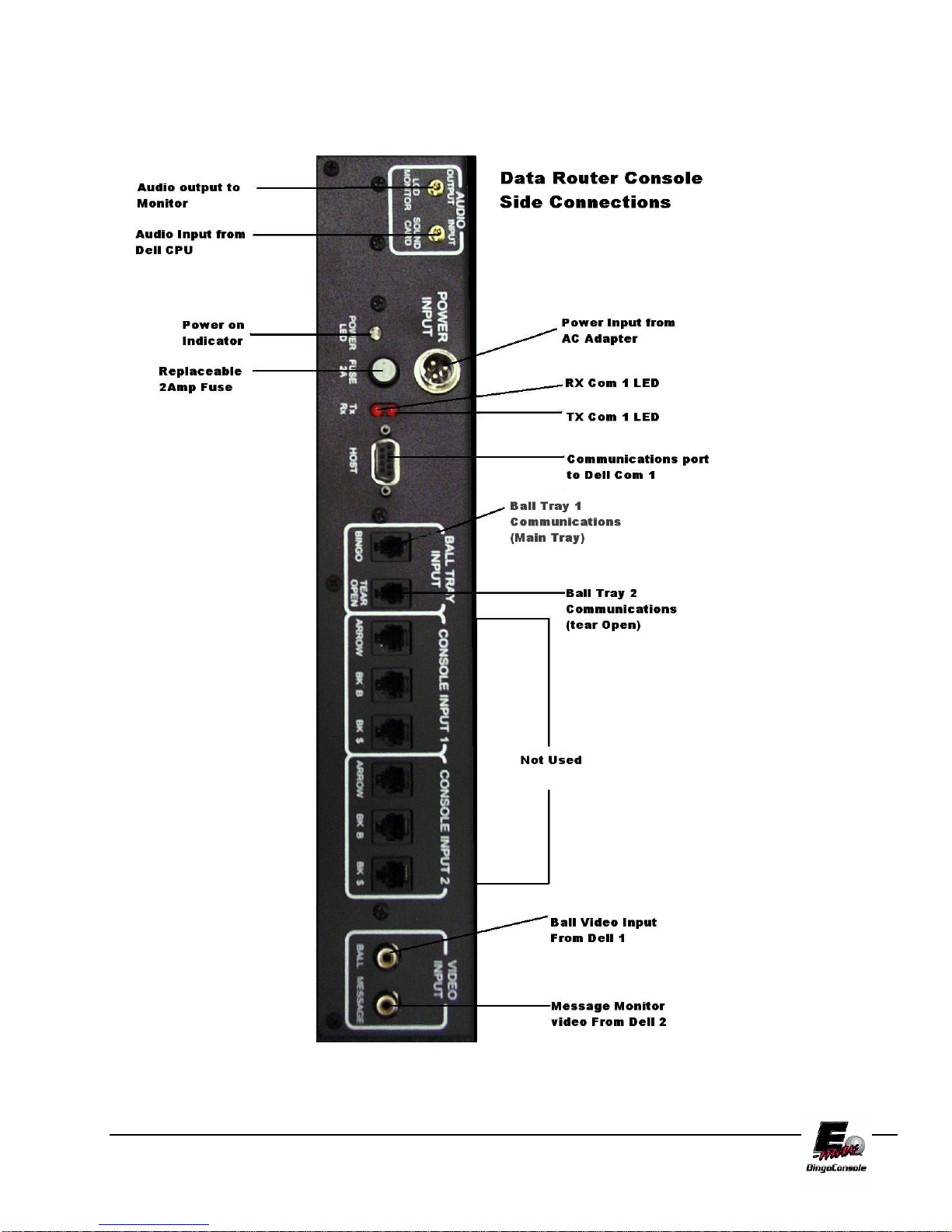
Data Router Console Side Connections
E-max Gaming Corporation, Inc.
76

Data Router Field Side Connections
E-max Gaming Corporation, Inc.
77

Data Router Field Connector Definitions
E-max Gaming Corporation, Inc.
78

RF Modulator Video Connections
Diagram
E-max Gaming Corporation, Inc.
79

E-max Gaming Corporation, Inc.
80

E-maxTM Bingo Console
Specifications
Disclaimer:
Not all consoles are shipped with identical specifications and equipment and
the following specifications are intended as a base line reference for the
performance of the E-max product line. Specifications are subject to change
without notice because of the dynamic aspect of the computer hardware and
software marketplace.
General Features of Electronics Console:
Slate gray wood cabinet with black trim, modular design
Heavy duty casters, rear locking front non-locking
Three key locks, two keys each
Sliding drawer for storage or printer or VCR
Graphics panel with light, standard Arrow artwork (HH525 Light Replacement)
UPS, Internal, 10 minute backup
Dell Computer:
Intel 2.4 GHz P4 CPU
512 MB RAM, 40 GB hard drive, CDRW drive,
Sound, 3 video ports, 6 USB ports,
1 parallel port, 3 serial ports, 2 Ethernet ports,
Full size keyboard, mouse
Operator display:
15" color LCD flat display:
Touc h pa nel, speakers, magnetic card reader
Data Router:
4 Arrow main flashboard outputs, each with both G.I., $value and status LEDs
2 BK B main flashboard outputs with status LEDs
2 BK $value flashboard outputs with status LEDs
1 Arrow & 1 BK Tear Open flashboard output with status LEDs
2 independent composite video outputs with RCA connectors
Software switched external video to two RF modulators
Software switched audio to operator display, monitors, PA system
Manual back up mode when Dell computer fails
Two RF modulator outputs for TV monitors, each with an RF input for external video
Operator Manual
CDs- restore application, database, and blank backup
Magnetic card reader for security access
1 year warranty
Appendix
B
E-max Gaming Corporation, Inc.
81

General Features of Ball Console
• 75 ball console
• Slate gray cabinet with black trim, modular design
• Red / Green / Silver ball chamber
• Arm rest
• Heavy duty casters, rear locking, front non-locking
• Sealed Ball bearing blower motor with power on/off switch
• Hepa air filter (HH246 Filter Replacement)
• Anti-static control and metal ball tube
• Dual ball chambers for reduced noise
• Integrated digital camera
• LED ball illumina tion
• Spill resistant rubber ball switches
• Raised ball for easy removal from ball tray
• Integrated ball tray computer
• Filler panels with cup holder and mounting rails to adjoin consoles
• 1 set of double numbered bingo balls
• Operator manual
• 1 year warranty
Detailed System Specifications
Size:
Electronics console:
27.5” wide x 34.5” deep x 30” high, + 17” high for the monitor
196 lbs
Ball console:
40.5” wide x 34.5” deep with arm rest, x 30” high, +4.5” high for ball tube
165 lbs
Electronics and Ball console adjoined: 69” wide
Electronics and two Ball consoles adjoined: 109” wide
Environment:
Indoor use only, no condensation
Recommended Operating Temperature: 15C to 35C (59F to 95F)
Storage temperature: -5C to 45C (23F to 113F)
Regulatory:
C-UL US Listing (pending)
Electrical:
Flashboard outputs:
0 to 5V output, up to 150ma sink or source, short circuit and ESD protected
Fused for severe damage
Video outputs:
Composite video – 0 to 5V max, 75 ohm output, RCA jack
RF modulator – channel 3 or 4, 75 ohm output, Type F connector
Video inputs:
RF signal level from TV out or similar source, Type F connector
Audio outputs:
0 to 5V max, signal levels and output impedance not intended to directly drive speakers, stereo 3.5 mm
receptacle
Audio input:
Signal levels compatible with standard PC sound card, MIC IN circuitry.
E-max Gaming Corporation, Inc.
82

Power Input:
60 Hz, 115 VAC nominal, 103 VAC min, 126 VAC max
Service feed wire must be 14 AWG or better and must be able to support 15 A.
Power should be reasonably free of noise and large surges.
Console will operate and provide fluorescen t emergency lighting for up to 10 minutes in the event of a power failure
Gaming Related Specifications:
Software Architecture:
MSWindows XP Pro operating system with custom Arrow gaming application shell.
Gaming operator never has access to the Windows operating system
Perms:
Verifies all Arrow paper perms – other perms available on special request
Tracks paper serial numbers
Security:
Three levels of system security for personnel access to equipment and gaming operations
User can change password
Encrypted hard drive and mechanical lock on Dell computer for maximum gaming security
Loads only Arrow generated gaming CDs
Operations:
Supports multiple organizations and multiple sessions on one console with security access
Operator can interchangeably use touch panel, keyboard, or mouse for input
Balls wrongly inserted in the ball tray can be easily reset on the operator screen
Live, digital ball camera image (picture-in-picture) on operator screen
Supports two cameras from the double ball console configuration
Automatically displays correct ball image and enables correct ball tray switches
Supports multilevel payouts and generates payout report
Hundreds of factory pre-loaded game patterns
Powerful, yet easy to use new pattern generator
Logs all gaming activity to a file which can be printed or recorded on a CD
Back up CDs can be generated to protect gaming setups and database
Console Operator Manual stored on the hard drive
Multi-media:
Sends dynamic or pre-programmed text or image ads to the Message monitor
Play Power Point presentations to the Message monitor
Dynamic or pre-programmed software controlled switching of interval and external video and audio signals
Supports external TV feed to the Message monitor
Supports VCR video, external linked gaming video, or other verify video to the Ball monitor
Networking:
Two Ethernet ports for maximum flexibility. (Customer specific applications)
Internal 56 K modem
Remote dial out application software – Future option
E-max Gaming Corporation, Inc.
83

E-max Gaming Corporation, Inc.
84

Wiring Diagrams
AC Outlet
Appendix
C
E-max Gaming Corporation, Inc.
85
 Loading...