

emaux UL-CP100, LED-CP100 Operating Manual
ROTARY TYPE UNDERWATER LIGHT OPERATING MANUAL
Keep this manual for future reference
Maintenance of the Lights
• Do not leave the lights directly under sunlight. Fill the pool with fresh water as soon as
possible after the lights are installed.
• Before switching on the lights, check whether the lights are fully submerged
underwater and the circuit boxes are running properly.
• This unit does not need any kind of maintenance. If it is not working properly, please
contact EMAUX authorized dealer where you purchase the unit from.
• Warranty will be voided if the Emaux Underwater Light was dismantled by
unauthorized personnel.
• Do not leave the lights “on” above water for longer than 1 minute.
SAFETY WARNINGS
• Avoid direct contact with electrical power.
• Respect all regulations in effect for preventing accidents.
• All units are required to be disconnected from the main electricity before any operation of
maintenance.
• Never handle with wet hands and feet.
• This unit is design for use only when fully submerged in fresh water, connecting with a safety
transformer.
• Never operate this Underwater Light for more than 1 minute unless it is totally submerged in
water.
• Be sure power is off before installing or removing light bulb. Allow light bulb to cool before
replacing.
• This product should be installed according to your local electrical installation ordinances and
regulations.
• Maximum Depth for Light installation at 1 meter.
o
• Maximum Water Temperature Range for light operation 0 - 30 C.
SPECIFICATION
A.Electrical Specification: 1) Voltage: AC12V 2) Frequency: 50Hz 3) Power: 75W(UL-CP100),
6W/8W(LED-CP100)
• Only qualified electrician is allowed to carry out the installation of this product.
1-44-4
UL-CP100
LED-CP100
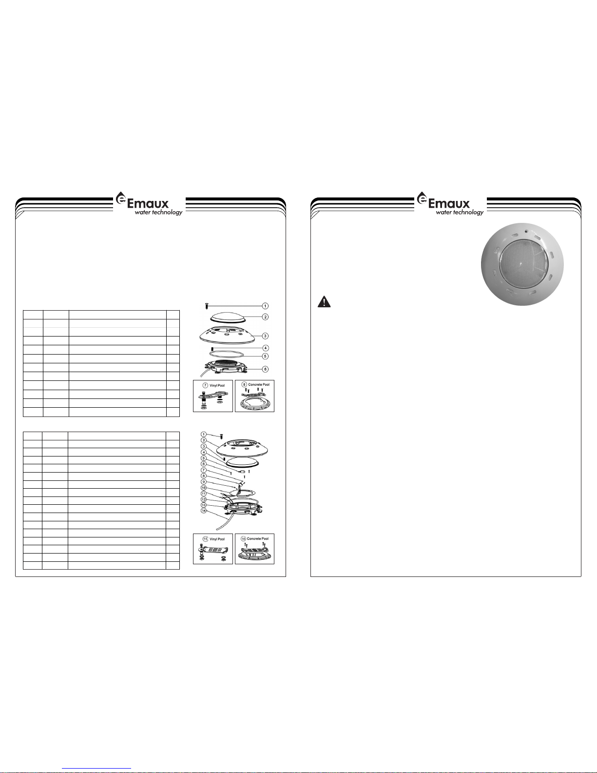
REPLACEMENT PARTS
INSTALLATION NOTES
1) Each cable is 2.5m long. You should follow the procedures closely when installing the light.
2
2) It is recommended to install a light every 20m , the approximate exposure area of each
unit.
3) The lights should be installed in the direction that they will not shine directly into the house.
4) For training or competition pools, the lights must be installed on the sides in order to
prevent swimmers from seeing any glare.
5) Nothing should be placed on the poolside directly above the lights for ease of future
maintenance.
6) If the wires are connected inside the lights, you must seal the connections with leak-proof
tapes or products with the same function.
EMLI16022769
Key N o.
Par t No.
Des cript ion
Qty
1
030 11321
M5X 20 scre ws (316 #)
1
2
010 40212
Lig hts Len s
1
3
010 12031
Fac e plate
1
4
011 10027
Com press ion scr ew
1
5
020 10237
O-r ing
1
6
890 45601
Bul b plate (Whit e Colou r),12 V/8W 19 8LEDs
1
6
890 45602
Bul b Plate (RGB) 1 2V/6W 1 02LED s
1
6
890 45603
Bul b Plate (RGB) 1 2V/8W 1 98LED s
1
6
890 45604
Bul b Plate (Whit e Colou r), 12V /6W 102 LEDs
1
7
890 44501
Lig hts Vin yl Pool F ittin g for P10 0/ CP10 0
1
8
890 40203
Lig hts Con crete P ool Fit ting fo r P100/ CP 100
1
LED -CP10 0
Key N o.
Par t No.
Des cript ion
Qty1030 11321
M5* 20 Scre w (316# )
1
2
010 50102
Fac e plate13
011 10027
Com press ion scr ew
14010 40212
Lig hts Len s15
040 11073
Bul b 12V/7 5W for UL H/ UL-N S
16030 11132
M4* 8 Screw37
030 11150
Scr ew28
040 11031
Lam p Socke t
19030 13039
But210
030 17118
Ref lecto r Plate
1
11
040 14016
Clo sed-E nd Wire C onnec tor
2
12
020 21084
O-R ing for U L-CP1 00
113012 31008
UL- CP100 L ight Bo dy Set
1
14
040 13004
2.5 M Cable
115890 44501
Vin yl pool F ittin g for P10 0
116890 40203
Fit ting fo r Concr ete Poo l
1
U -CP1 00L
Concrete must be cut
backaround niche to
allow fora compact
plaster seal
120cm min.
Water level
Rigid conduit
Junction
box
45cm min. from water
line to top of lens
6.6cm
29.6cm
Figure 3
Mounting plate
O-ring
Nut
≤30m
Tra ns former
Ligh t
Figure 2
INSATALLATION OF THE UNDERWATER LIGHT
A) Preparing to Install
1 Before installation, a circuit system
diagram must be designed by a
certified engineer.
2) The circuit system must comply with
local laws and regulations and
must be carried out by qualified
electricians.
3) Make sure the voltage is 12V and
the terminal box is at least 120cm
from the poolside (Figure 3).
4) Upon installation, top of the light
must be at least 45cm from water
surface (Figure 3).
)
6) The wire connections inside the terminal box must be sealed by leak-proof tapes to
prevent water from leaking into the terminal box through the cables.
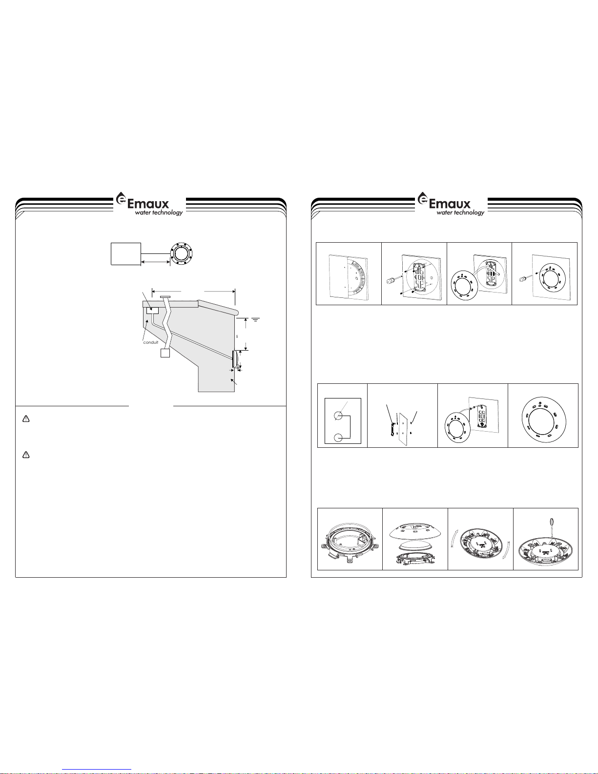
C)
1) Refer to section "Preparing to Install”.
2) Make 2 holes on the pool wall (Figure 8).
3) Place the o-rings between the Mounting Plate and the pool wall and tighten it with the Nut on
the other side of the pool wall (Figure 9).
4) Put the cable sequentially through the sealing Nut, the sealing O-ring and the cable hole on
the mounting plate; then tighten the Nut (Figure10).
5) Wrap extra cables behind the light to make sure it could be taken to the pool surface for
future maintenance. Then, hang the light onto the Mounting Plate and tighten the screws
(Figure 11).
Fiberglass Pools / Vinyl Pools Installation
Figure 9 Figure 10Figure 8 Figure 11
2X24
147,5
3-42-4
Never o per at e thi s Under water L igh t fo r mor e than 10 s eco nd s unl es s it is
total ly su bm erg ed in wat er. Wit hou t to tal s ubmer sio n, t he li gh t ass embly w ill
get ext rem el y hot , which m ay resu lt in s er iou s injur y to po ol u ser s, i nst aller s, or
bysta nde rs , or in d amage t o prope rty .
Be sure p owe r is o ff be fore in stall ing o r re mov ing lam p. Al lo w lam p to c ool
befor e rel am pin g.Thi s light f ixt ur e use s a Halog en Quar tz la mp . Do No t touch
lamp wi th ba re h and , this ma y sever ely r ed uce i ts life . Use the p las ti c fur nishe d
with th e rep la cem ent lam p to elim ina te f ing er prin ts fr om g ett in g on la mp.
Figure 6
Figure 7
Figure 4
Figure 5
2
7) The cables connecting the lights and the transformers must be at least 6mm and the
distance between them must not exceed 30m (Figure 2); otherwise the lights will not
function properly.
B) Pool Installation
1) Embed the Wall Mount into the concrete wall, making sure that it is parallel to the side
of the pool(Figure 4).
2) Place the Mounting Plate on the concrete wall and tighten it with 4 screws. The conduit
must be next to the Mounting Plate (Figure 5).
3) Note that the light must only be installed on a flat or concave surface.
4) Wrap extra cables behind the light to make sure it could be taken to the pool surface
for future maintenance (Figure 6).
5) Hang the light onto the Mounting Plate and tighten the screws (Figure 7).
D)
1) Clean the O-ring installation position and put the O-ring.
2) After install the O-ring. Put the transparency lid and then put the cover. (Figure 13)
3) While install the cover with the base, please to note that the sign of “TOP”from the base
should meet with the sign of “TOP for the cover. (Figure 14)
4) Rotate to the station position and then to use screw driver that to tighten. (Figure 15)
5) For Unassembled, please to reverse the sequence.
Assembly for CP100
(Figure 12)
Figure 12 Figure 13 Figure 14 Figure 15
WARNING
 Loading...