

emaux ST Series, STA Series Instructions Manual
Before installation, be sure to read all instructions and warnings carefully.
Refer to product data plate(s) for additional operating instruction and specifications.
INSPECTION
Examine the equipment when received. Notify your dealer or carrier of any damage or
missing parts. Verify that equipment is of size and model specified.
When installing and using this electrical equipment, basic safety precautions should
always be followed, including the following:
1) READ AND FOLLOW ALL INSTRUCTIONS.
2) WARNING - To reduce risk of injury, do not permit children to use this product unless they
are closely supervised at all times.
3) WARNING - (For cord & plug connected units) risk of electric shock. Connect only to a
grounding type receptacle protected by a ground-fault circuit-interrupter(GFCI).
Contact a qualified electrician if you cannot verify that the receptacle is protected by a
GFCI.
4) WARNING - (For cord & plug connected units). To reduce the risk of electric shock,
replace damaged cord immediately.
5) WARNING - (For cord & plug connected units). To reduce the risk of electric shock do not
use an extension cord to connect unit to electric supply; Provide a properly located
outlet.
6) WARNING - (For hot tub and spa pumps). Do not install within an outer enclosure or
beneath the skirt of the hot tub or spa, unless so marked.
7) SAVE THESE INSTRUCTIONS
IMPORTANT SAFETY INSTRUCTIONS
EMPU16 02275 5
ST & ST Series PumpA
14
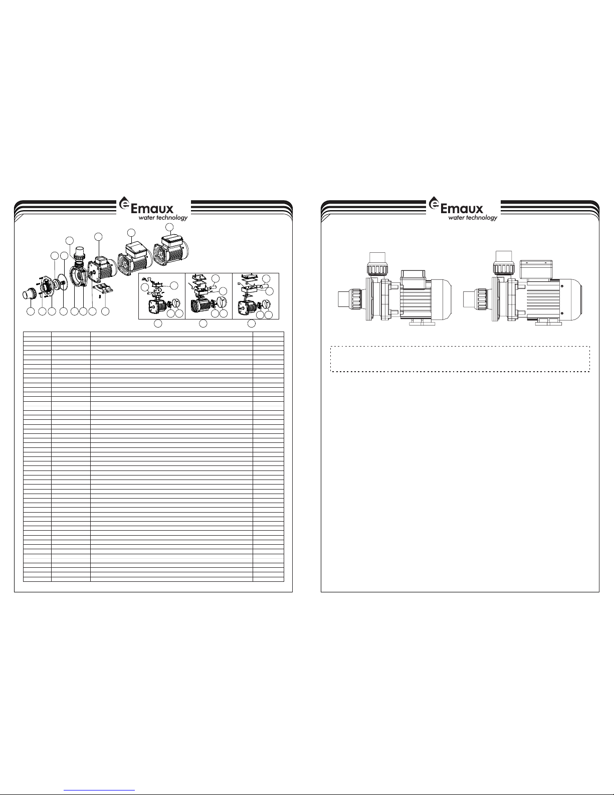
PUMP PAR TS FO R S T
Key No.
Part No .
Descr iptio n
Qty
1*
89280 105
1.5"u nion (B lack/ W hite Co lour)
2
2
89022 103
M5*16 S crew fo r pump fr ont wit h Washe r
6
3
01021 046
ST SD Pum p Body Co ver
1
4
02011 076
O-Rin g for Pum p Body
1
5
01311 015
Impel ler SD0 20/SD 50/SQ 20/SQ 50/SS 20/SS 50/ST 20/ST 50
1501311 016
Impel ler SD3 3/SD7 5/SQ3 3/SQ7 5/SS3 3/SS7 5/ST3 3/ST7 5
1
5
01311 017
Impel ler SD0 50/SD 100/S Q050/ SQ100 /SS05 0/SS1 00/ST 050
1
5
01311 018
Impel ler SD0 75/SD 120/S Q075/ SQ120 /SS07 5/SS1 20/ST 075
1
5
01311 019
Impel ler SD1 00/SQ 100/S S100/ ST100 (220V /50HZ )
1
5
01311 014
Impel ler SS1 20(22 0V/50 HZ)
1
5
01311 023
Impel ler SD0 20/SQ 020/S S020/ ST020 (220V ,110V /60HZ )
1501311 024
Impel ler SD0 33/SQ 033/S S033/ ST033 (220V ,110V /60HZ )
1
6
04015 033
1/2" Me chani cal Sea l
1
7
01021 024
SD SQ ST Pu mp Body
1
8
89022 104
M8 x 25 Scr ew with W asher f or Moto r
4902011 156
Motor S linge r
1
10
89022 109
Motor S D020/ SQ020 /SS02 0/ST0 20(22 0V/50 HZ)
1
10
89022 110
Motor S D033 (2 20V/5 0Hz)
1
10
89022 105
Motor S D050/ SQ050 /SS05 0/ST0 50(22 0V/50 HZ)
11089022 106
Motor S D075/ SQ075 /SS07 5/ST0 75(22 0V/50 HZ)
11089022 107
Motor S D100/ SQ100 /SS10 0/ST1 00(22 0V/50 HZ)
1
10
89022 108
Motor S D120/ SQ120 /SS12 0/ST1 20(22 0V/50 HZ)
11089022 201
Motor S D/SQ/ SS/ST 020(2 20V/6 0HZ)
1
10
89022 202
Motor S D/SQ/ SS/ST 033(2 20V/6 0HZ)
1
10
89022 203
Motor S D/SQ/ SS/ST 050(2 20V/6 0HZ)
1
10
89022 204
Motor S D/SQ/ SS/ST 075(2 20V/6 0HZ)
1
10
89022 205
Motor S D/SQ/ SS/ST 100(2 20V/6 0HZ)
1
10
89022 206
Motor S D/SQ/ SS/ST 120(2 20V/6 0HZ)
1
10
89022 305
Motor S D/SQ/ SS/ST 020(1 10V/6 0HZ)
1
10
89022 306
Motor S D/SQ/ SS/ST 033(1 10V/6 0HZ)
1
10
89022 301
Motor S D/SQ/ SS/ST 050(1 10V/6 0HZ)
1
10
89022 302
Motor S D/SQ/ SS/ST 075(1 10V/6 0HZ)
1
10
89022 303
Motor S D/SQ/ SS/ST 100(1 10V/6 0HZ)
1
10
89022 304
Motor S D/SQ/ SS/ST 120(1 10V/6 0HZ)
1
11
89022 101
Base wi th M5 x 20 Sc rew
1
12
04016 028
Capac itor fo r SS/SD /SQ/S T050 Pu mp 110V
1
12
04016 019
Capac itor fo r SC050 & S S/SD/ SQ/ST 075 Pum p 110V
1
12
04016 021
Capac itor fo r SC075 & S S/SD/ SQ/ST 100-1 24 Pump 1 10V
1
12
04016 009
Capac itor fo r SS/SD /SQ/S P/ST0 50 Pump
1
12
04016 010
Capac itor fo r SS/SD /SQ/S P/ST0 75 & SC05 0 Pump
1
12
04016 012
Capac itor fo r SS/SD /SQ/S P/ST1 00-12 0
11204016 032
Capac itor fo r SS/SD /SQ/S T020 Pu mp 110V
1
12
04016 033
Capac itor fo r SS/SD /SQ/S T033 Pu mp 110V
1
12
04016 030
Capac itor fo r SS/SD /SQ/S T020 AM U020P /TP(5 0/60H z)
1
12
04016 031
Capac itor fo r SS/SD /SQ/S T033 Pu mp
1
13
89022 111
Cable B ox for SQ /ST/S D020- 033, SS 020-S S030 Pu mp
1
14
89022 112
Cable B ox for SD ,SQ,S P,ST0 50-12 0 Pump
1
15
89021 505
Cable B ox for ST 050-S T075 Pu mp (110 V/60H Z)
1
16
01031 027
Cooli ng fan fo r SS/SD /SQ/S T050- SS/SD /SQ/S T120 Pu mp
11601031 026
Cooli ng fan fo r SS/SD /SQ/S T020- SS/SD /SQ/S T030 Pu mp
1
17
01031 011
Fan Cov er for SS /SD/S Q/ST0 20-SS /SD/S Q/ST0 30 Pump
1
17
01031 010
Fan Cov er for SQ /SP/S S/SD/ ST050 -SQ/S P/SS/ SD/ST 120
1
18
02011 104
O-Rin g for 1.5 " Union
2
Notes :1* 892 80105 B is 1.5" union i n Black C olour
1* 8928 0105W i s 1.5"u nion in W hite Co lour
1 2
3
4
5
678 9
11
18
10
10
10
13
10
12
16
17
12
14
16
17
10
16
17
15
12
10
220 V 50HZ 220 V 50HZ 110V 6 0HZ

Locate pump as close to pool/spa as possible, preferably in a dry, well ventilated area
away from direct sunlight. It should be on a hard, level surface. Give consideration to:
1) Drainage -away from pump
2) Ventilation of pump motor
3) Access for future servicing and winterizing
4) Protection from the elements
Pumps without strainer bodies are designed for flooded suction (all suction fittings and
suction piping below water level) and will not self-prime. Consequently, the pump must be
installed at an elevation that is below water level when pool or spa is filled.
GENERAL PLUMBING
Rigid or flexible PVC pipe can be used. Pipe ends should be clean and free of any flash
caused by the cutting operation. Be sure that the proper solvent is used on type of pipe
specified.
Caution: We recommend that consider climatic conditions when applying adhesives,
make the adhesive action of certain glues less effective. Check the manufacturer's
instructions.
Refer to information on motor nameplate for electrical service data. All motors should
have fused disconnect switch or circuit breaker. Be sure wire size is sufficient for pump hp
and distance from power source. Wiring should be done in accordance with applicable
codes by a competent electrician.
Do not operate pump until it has been primed as water acts to cool and lubricate the seal.
For pumps without strainer bodies and located above water, close suction line valve and
fill pump with water in order to prime. If no flow is observed in five minutes, stop the motor
and re-prime. If the pump fails to operate, check for air leaks. Refer to trouble shooting
section.
Suction pipe should be as large or large than discharge pipe avoid using a suction pipe
smaller than pump connection.
Keep the piping as straight and short as possible, and of suitable size. Avoid connecting an
elbow directly into the pump inlet(use a length of straight pipe to allow a proper entry for
the water).arrange horizontal runs to slope upward to the pump to prevent high spots that
could form air pockets. Support the piping independently so that it places no strain on the
pump. Keep as much of the suction line as possible below the water level to reduce
priming time.
FOR SOLVENT WELD CONNECTION
ELECTRICAL DATA
PUMP START UP
PUMP PLUMBING
TROUBLE SHOOTING
1) Motors are self-lubricating no lubrication required.
2) Shaft seals may become worn and must be replaced if leakage is observed.
NOTE: If the recommendations in the trouble shooting portion of this manual do not solve
your particular problem(s), please contact your local dealer for service.
Refer all service to your local dealer as his knowledge of your equipment makes him the
vest qualified source of information. Order all repair parts through your dealer. Give the
following information when ordering repair parts:
1) Unit nameplate data.
2) Description of part.
SERVICE & REPAIR PARTS
Motor does not start
1) Disconnect switch or circuit breaker in
off position
2) Fuses blown or thermal overload open
3) Locked motor shaft
4) Motor windings burned out
5) Defective starting switch inside sing
phase motor
6) Disconnected or defective wiring
7) Low voltage
Low pump capacity
1) Suction or discharge line partly
plugged
2) Suction or discharge line too small
3) Pump running at reduced speed
4) Impeller clogged
Pump delivers no water
1) Pump is not primed
2) Leakage or air into suction system
3) Impeller clogged
Noisy pump and motor
1) Worn motor bearings
2) Suction line partly plugged
Leakage of water at shaft
Shaft seal requires replacement
High pump pressure
Return lines too small
Pump does not reach full speed
1) Low voltage.
2) Pump connected for wrong voltage.
Motor overheats
1) Low voltage
2) Inadequate ventilation
Air bubbl es a t i nle t fitt ing s
1 Leaka ge o f air i nto su cti on lin e at
conn ectio ns o r v alv e stem
2 Low water lev el in d rai n o f ba th
)
)
INSTALLATION LOCATION
PUMP MAINTENANCE
32
 Loading...