

Page 1
1
SALT CHLORINATOR
USER MANUAL
SSC
mini
®
Page 2
2
1. SAFETY GUIDE
IMPORTANT: The instruction manual you are holding includes essential information on the safety
measures to be implemented for installation and start-up. Therefore, the installer as well as the
user must read the instructions before beginning installation and start-up.
Keep this manual for future reference.
When using this electrical equipment, basic safety measures listed below should be followed:
Disconnect all AC power during installation.
To reduce the risk of injury, do not permit children to use this product unless they are closely supervised.
A green colored terminal marked "Earth Ground" is located inside the wiring compartment. To reduce
the risk of electric shock, this terminal must be connected to the grounding means provided in the
electric supply service panel with a continuous copper wire equivalent in size to the circuit conductors
supplying the equipment.
To reduce the risk of electric shock, connect the local common bonding grid in the area of the swimming
pool or spa to these terminals with an insulated or bare copper conductor.
2. CONTENTS OF PACKAGE
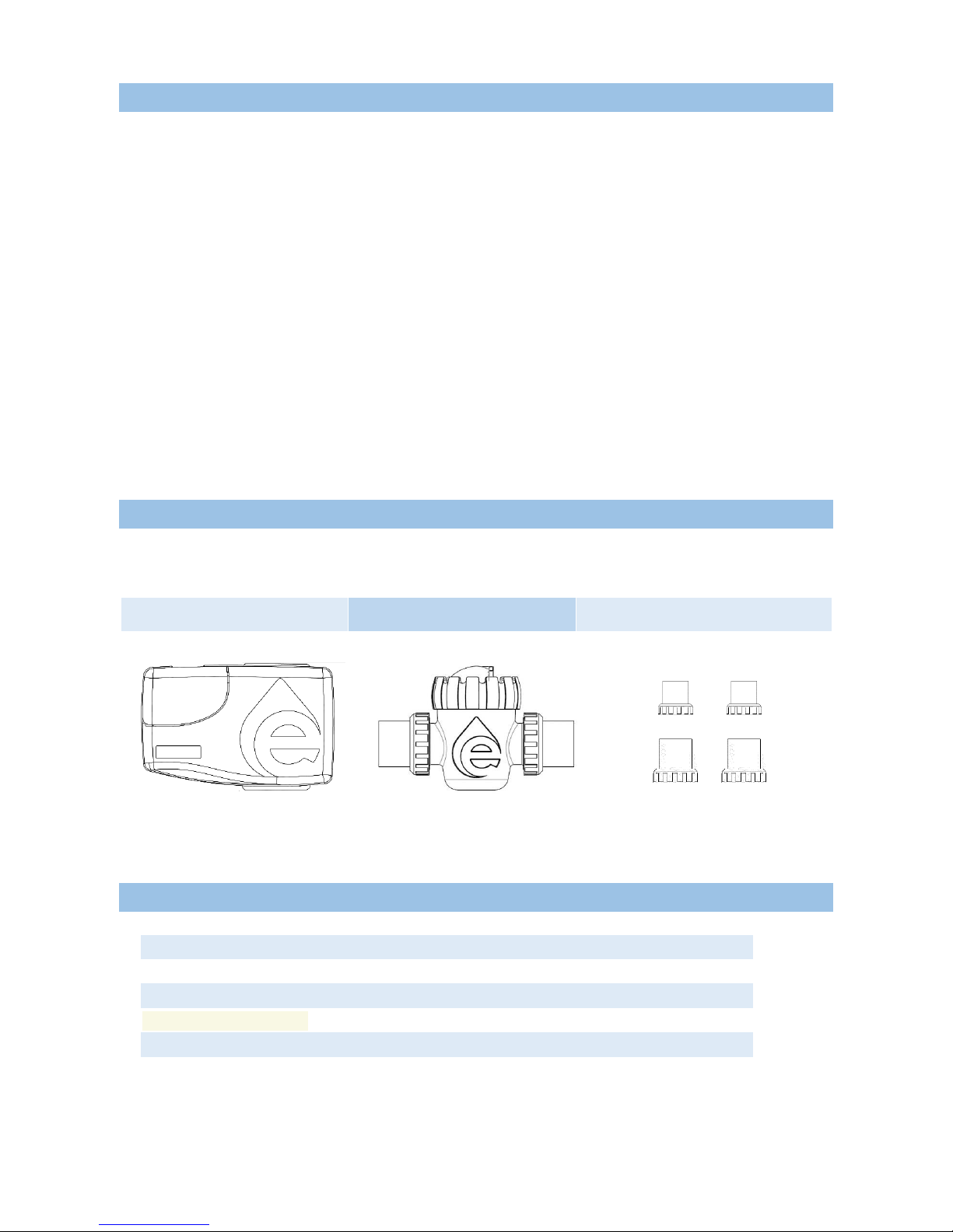
Following components are contained in the package:
SSCmini® Control unit
SSCmini® Electrolytic Cell
1.5” and 2” Universal Unions
3. SPECIFICATIONS
Standard working voltage
220-240 V AC – 50/60 Hz
Maximum chlorine production
20 g/h
Maximum Pool Volume
90 m³
Water salinity required
4 – 6 g/l
Working Temperature of Water
10°C – 45°C (50°F – 113°F)
Electrodes
Titanium plates
Page 3

3
4. INTRODUCTION
Emaux SSCmini® is an automatic chlorine generation system for pool sanitization and it is composed by two
main components: an electrolytic cell and a control unit.
4.1 ELECTROLYTIC CELL
The electrolytic cell is composed by a number of titanium plates (electrodes) placed in a cell holder. The
control unit regulates electrical current that passes through the titanium plates. One extreme of the plates
will be anode and the other will be cathode.
Adding a certain concentration of salt in the water, this passes through the plates and thanks to the
electrical current, the Hypochlorous acid is produced.
The following chemical reactions are produced in the plates of the electrolytic cell:
Positive pole (anode): 2 H2O O2 + 4 H+ + 4e
-
2 NaCl Cl2 + 2 Na+ + 2eNegative pole (cathode): 2 H2O + 2e- H2 + OHFinal chemical reaction: Cl2 + OH- HClO + Cl-
The operation requires a certain concentration of salt (4000 ppm), low enough that it normally will not
be tasted. The SSCmini® automatically sanitizes your pool by converting the salt into Hypochlorous acid
which kills bacteria and algae in the pool through a process called electrolysis.
Because chlorine will revert back to sodium chloride after killing the bacteria, the above reactions will
continuously recycle virtually eliminating the need to add sanitizing chemicals to your pool. The only time
you may need to add more salt to the pool is when water is replenished due to backwashing, draining,
or splashing.
4.2 CONTROL UNIT
The control unit is provided with a microprocessor driven control system to regulate operation time and
inform about SSCmini® operation status and errors. The system also includes a self-cleaning procedure
that avoids scale formation on the electrodes.
5. SAFETY WARNING AND RECOMMENDATIONS
The equipment should be assembled and handled by truly qualified people.
Current electrical and accident prevention regulations should be followed.
Under no circumstances will the manufacturer be held responsible for the assembly, installation or start-up,
nor any handling or fitting of components unless they are carried out on its premises.
The working voltage of SSCmini® is 220-240V, 50/60Hz. Do not attempt to alter the system to operate at
a different voltage.
Check all the electrical connectors to avoid false contacts and their consequent overheating.
Before installing and replacing any component, disconnect the control unit from the main power supply;
only replacements provided by Emaux can be used for replacing.
The control unit must be installed in places with sufficient ventilation. The equipment should not be installed
Page 4

4
near flammable materials.
This equipment should never be installed in places susceptible to flooding.
It is important to reduce chlorine production properly while the pool is covered. Otherwise, an excess of
chlorine could degrade the pool materials.
6. WATER CHEMISTRY
The following table shows the recommended levels of the chemical parameters required for a proper quality
of water in the pool by using Emaux SSCmini®.
Test your water periodically and ensure the levels are within the recommended range.
Salt Level
4000 – 6000 ppm
Free Chlorine
1.0 – 3.0 ppm
pH Value
7.2 – 7.6
Cyanuric Acid (stabilizer)
30 – 50 ppm
Total Alkalinity
80 – 120 ppm
Calcium Hardness
200 – 400 ppm
Metal
0 ppm
6.1 SALT LEVEL
The amount of salt required when using Emaux SSCmini® is between 4000 and 6000 ppm. To reach
this concentration, it is necessary to 4 kg of salt per each cubic meter of pool water.
Low salinity (below 2500ppm) will cause premature cell failure. High salinity (above 6000ppm) will result
in electro-oxidation and the corrosion of stainless steel swimming pool fixtures.
Salt required according to the pool volume:
Pool volume (m3)
Salt (kg)
Pool volume (Gallon)
Salt (Pound)
10
40
2,642
88
15
60
3,963
132
20
80
5,283
176
25
100
6,604
220
30
120
7,925
264
35
140
9,246
308
40
160
10,567
352
50
200
13,209
440
60
240
15,850
528
70
280
18,492
616
80
320
21,134
704
90
360
23,775
792
100
400
26,417
880
Note: Table based on 4000 ppm of salt per m3 of water.
Page 5
5
6.2 TYPE OF SALT
The most common salt used in swimming pools with Salt Electrolysis is Sodium Chlorine (NaCl) that is
99% pure. DO NOT use the following types of salts:
rock salt;
salt with more than 1% yellow prussiate of soda;
Salt with more than 1% of anti-caking additives;
Iodized salt.
6.3 ADDING AND REMOVING SALT
Before adding the salt into the pool, turn your filtration pump on and set your filtration valve manifold in
position “Filtration”. Add the salt directly into the pool or balance tank and do not allow the salt to sit in
a pile on the bottom of the pool. Keep the filtration system running for 24 hours using a main drain or a
vacuum suction nozzle as a main suction line.
The only way to remove the salt in the pool water is to partially drain the pool and refill with fresh water.
7. INSTALLATION
7.1 CONTROL UNIT INSTALLATION
The Emaux SSCmini® control unit is contained in a raintight enclosure that is suitable for outdoor
mounting (IPX4 rating). However, the following points must be taken into consideration for a correct
installation of the control unit:
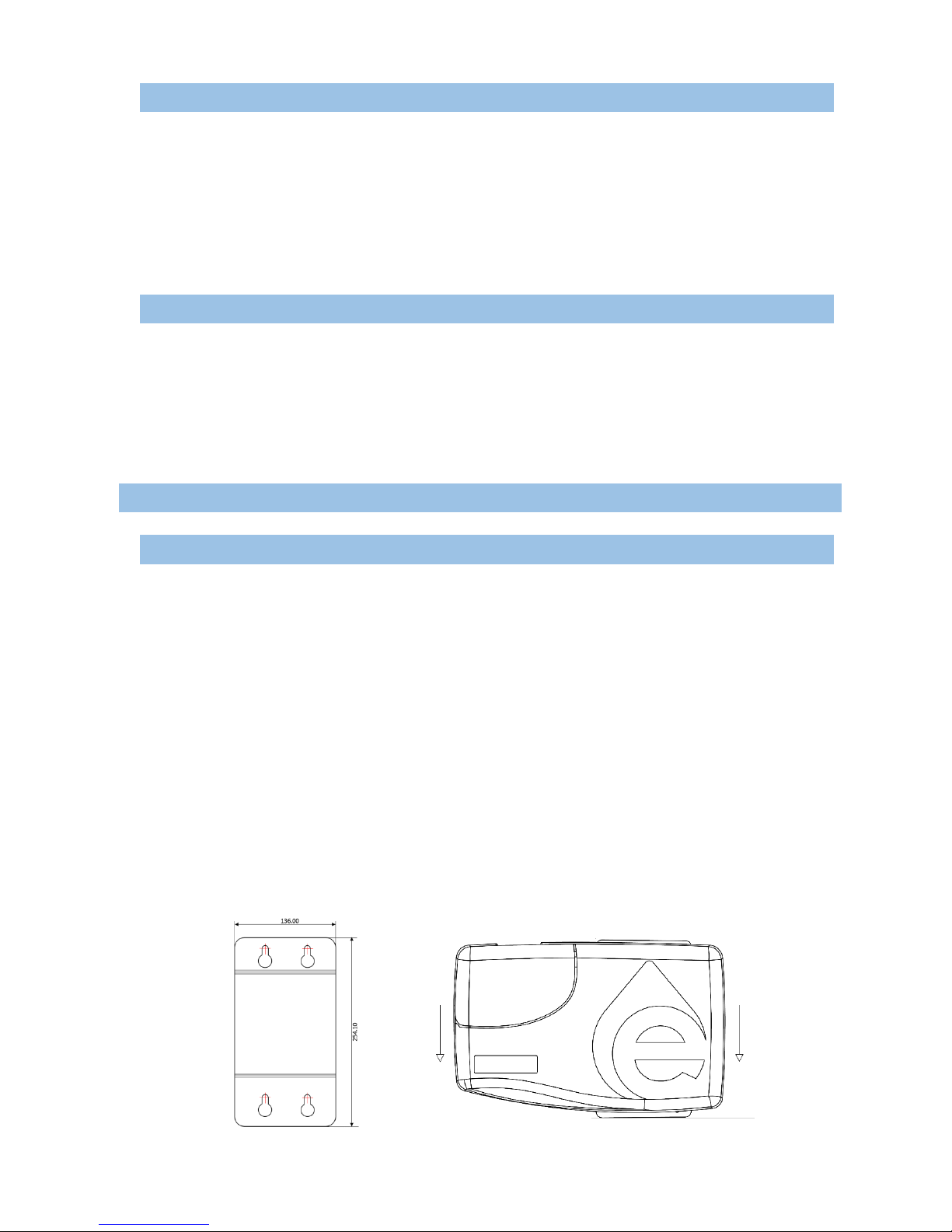
1. Install the Control Unit using the mounting template provided with the package. The unit should be
installed in a minimum distance of 3 meters from the swimming pool, 1.5 meters from the ground,
within 2 meters from electrical enclosure, and within 3 meters from where the cell will be installed.
2. Fix the mounting template on the wall and drill 4 holes with a diameter of 8mm in the wall according
to the mounting template (Figure 1). Use expansion bolts to support the control unit.
3. Hang the control box on the fixed bolts (Figure 2) and make sure that the power cable and cell cable
also reach the Control Unit.
4. Don’t install the control unit under direct sun light.
5. The control unit should be installed away from chemicals storage.
6. The unit must be kept away from heat sources and any equipment which produce heat.
7. Plug-in power supply into a suitable weatherproof outlet socket with circuit breaker.
Figure 1
Figure 2
Page 6
6
7.2 ELECTROLYTIC CELL INSTALLATION
Please follow the recommendations below to install the electrolytic cell properly:
1. The electrolytic cell should be mounted once the installation of all other swimming pool equipment
is completed (filtration pump, filter, heating system).
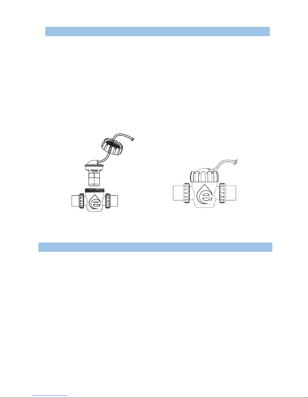
2. The electrolytic cell is designed to install in PVC pool plumbing. The opening of the cell holder must
be placed upright to enable the maintenance of titanium plates. To install the cell, cut off at least
187mm of pipe. Fix the electrolytic holder on the pipe, put the electrodes into the cell. Make the
electrode cable go through the nut (Figure 3).
3. Connect the unions to the pipe and make necessary adjustments for a proper connection. Once
adjusted, fix the connection with PVC glue and tighten the union nuts.
4. Fix the electrodes inside the holder and tighten the nut of the cell; connect the electrode cable to the
control unit; tighten the nut to ensure the good contact (Figure 4).
Note: the cell can also be installed in a vertical position.
8. START-UP
Before starting up Emaux SSCmini® unit, the following points have to be taken into consideration:
1. Check if the filter is completely clean, and ensure that the swimming pool and the installation do not
contain any metals dissolved or algae.
2. Ensure that the heating equipment (if any) is suitable for use in salt water.
3. Ensure that chemical parameters of pool water are within the recommended range (see Chapter 6).
4. Run your filtration system for 24 hours before starting salt chlorinator so that salt in the swimming pool
is completely dissolved.
For start-up, set the system at 50% of working time. It will take a few days of adjustments to find the most
appropriate setting according to the chlorine demand of your swimming pool. Once determined, only minor
adjustments might be necessary in cases of splashing, backwashing, rain, etc.
The temperature of the water is a parameter that effects the chlorine production. When the temperature rises,
chlorine will be easily volatilized affecting sanitizing effect. The water temperature should be within the range
of 15-40ºC. The Emaux SSCmini® will not produce chlorine at temperatures below 10º C.
Figure 4
Figure 3
Page 7
7
The desired level of chlorine generation should be modified according the following parameters:
1. Pool water temperatures increases or decreases significantly
2. When there is a higher load of bather than normally
3. When the cell’s life time is finishing
4. In a long period of inactivity or winterizing
9. OPERATION
SSCmini® salt chlorinator is managed through a control panel that regulates chlorine production and
informs about operation status.
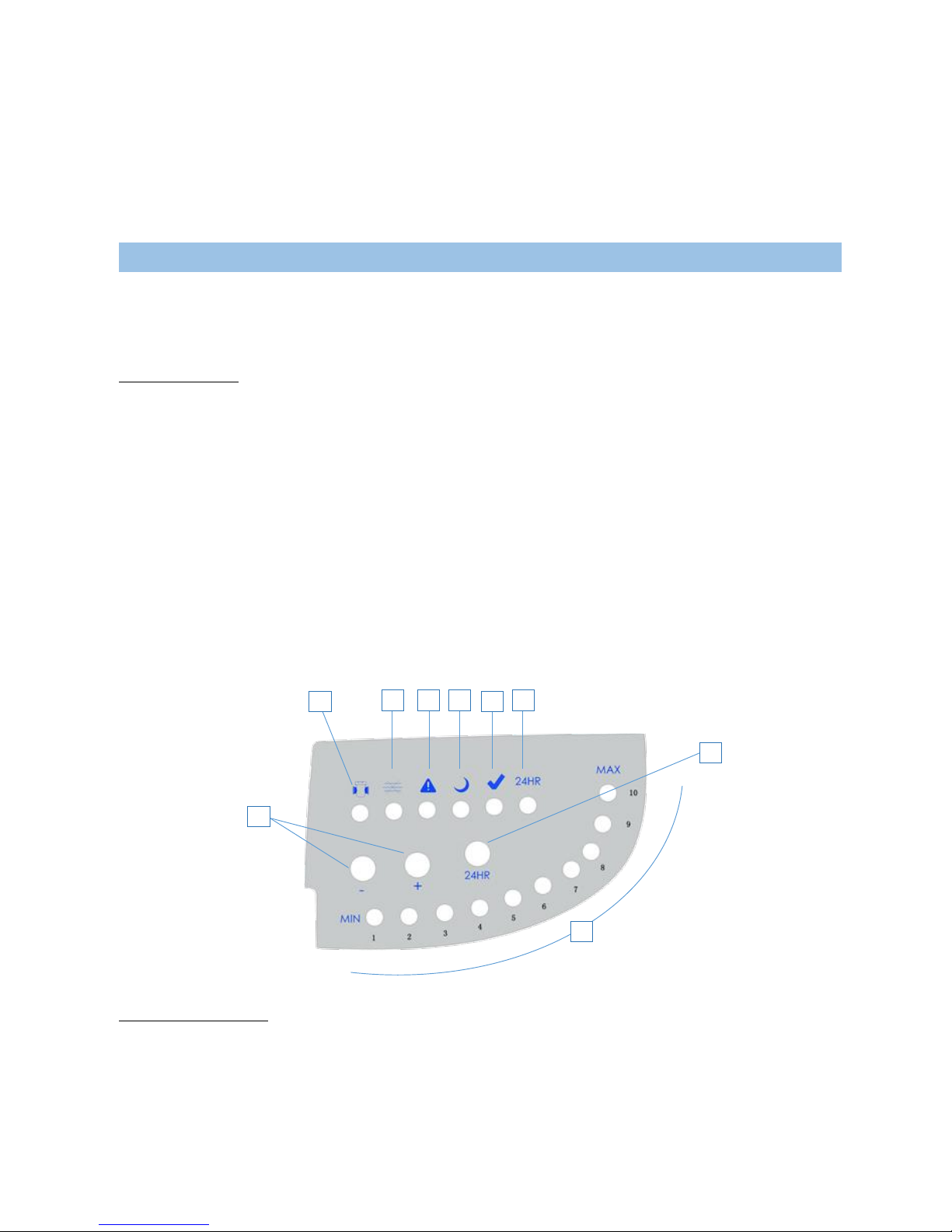
LED INDICATORS
1. Cell life low. Illuminates when the cell reaches the end of its expected life. In this case, the cell
electrodes have to be replaced.
2. No flow. Water flow is not detected, or water flow is too low. If operation schedule is not active, no
action should be done, otherwise refer to the Troubleshooting guide (Chapter 12).
3. Alarm. The unit is not working properly. Refer to the Troubleshooting guide (Chapter 12).
4. Stand-by. The unit is in-between operation cycles.
5. Normal operation. Electrolytic cell is generating chlorine under normal conditions.
6. Superchlorination. Superchlorination mode is active. Electrolytic cell will be generating chlorine
during 24 hours.
7. Work schedule. These 10 LEDs, from 1 to 10, correspond to a working hour, each LED represents 6
minutes. If all 10 LEDs illuminate, the unit will be generating chlorine without stop. If 5 LEDs illuminate,
the unit will be generating chlorine during 30 minutes of each working hour.
CONTROL BUTTONS
8. Work schedule control: Press “+” and “-“ to adjust working time. The LEDs below will illuminate as
explained above.
9. Superchlorination: Press the button to activate Superchlorination mode. The cell will be generating
chlorine during 24 hours. To exit superchlorination mode, press the button again.
1 2 3 4 5 6 8 9 7
Page 8
8
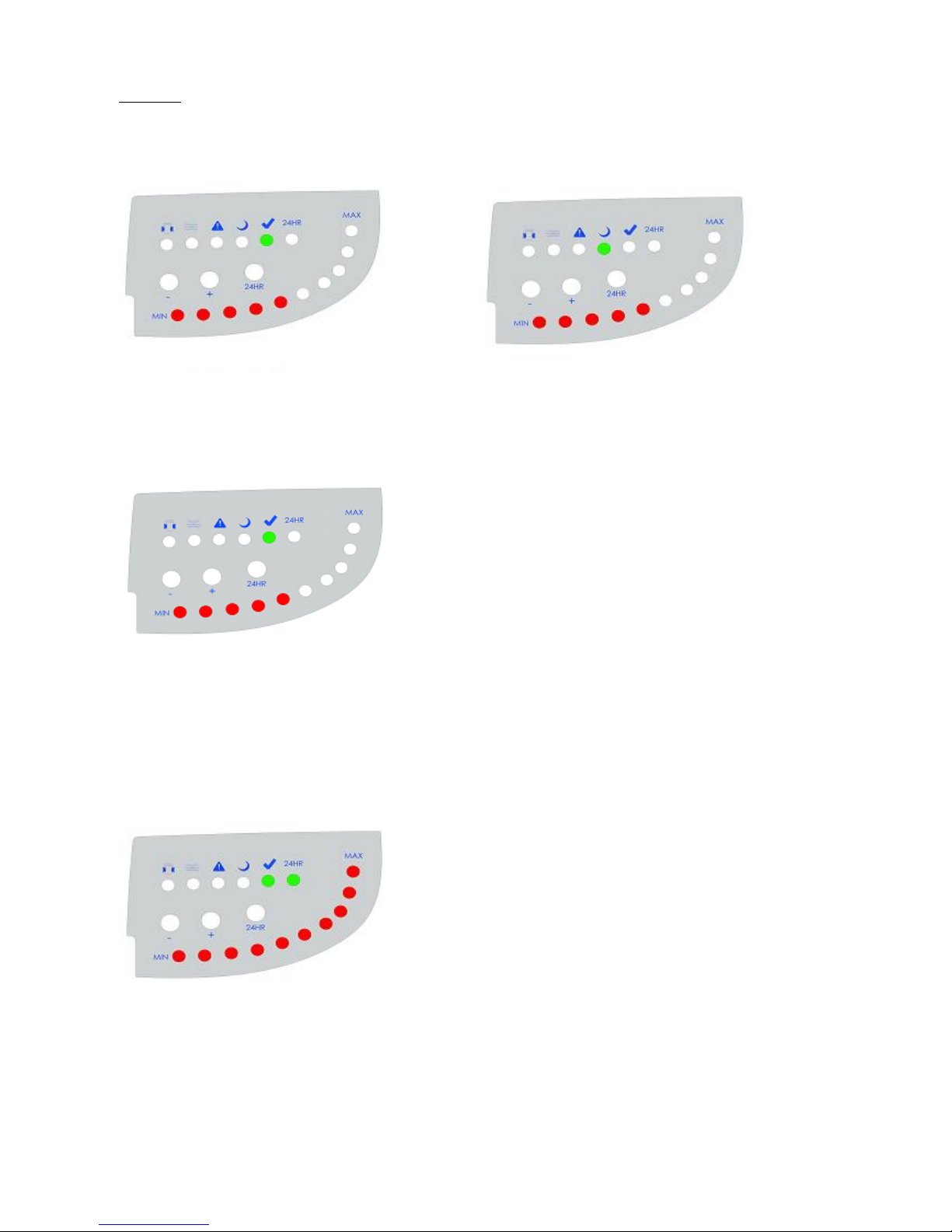
EXAMPLE
If you start SSCmini® at 9:00 and set the work schedule at 5, then the unit will be working from 9:00 to
9:30 (Normal operation LED is ON) and in stand-by mode from 9:30 to 10:00 (Stand-by LED is ON).
A new cycle will start at 10:00 until 10:30, and so on.
If you activate Superchlorination mode at 10:30 (Superchlorination LED is ON), then the unit will be
working until 10:30 of the next day and will exit Superchlorination mode afterwards. Once finished
Superchlorination, the schedule will be restored and a new cycle will start.
09:00 – 09:30
09:30 – 10:00
10:00 – 10:30
10:30 – next day 10:30
Page 9

9
10. MAINTENANCE
Due to the Reverse Polarity system that avoids scale in the plates of the cell, the first action to consider for
ensuring a long cell lifetime is to keep the chemical parameters always in the recommended range, especially
the amount of salt, the pH and the water hardness.
1. Keep the salinity of the water always higher than 3000 ppm in order to avoid premature deterioration
of the cell plates. The following formula determines the amount of salt to be added in the pool due to low
salinity:
Q = (4-S) x V
Where Q = quantity of salt (kg) to be added.
4 = correct salt concentration (constant).
S = Measured salt content in the pool
V = Volume of the pool in m3.
2. Keep the pH between 7.2 and 7.6. Check and clean the cell plates if the system has been working for
a prolonged period with a pH value over 7.6.
ELECTROLYTIC CELL CLEANING PROCEDURE
If scale has formed on the titanium plates, the first cleaning procedure is as follows:
1. Switch off the power supply of SSCmini
®
control unit and remove electrodes from the cell.
2. Once removed, look inside and inspect for scale formation on the plates and for any debris which
has passed through the filter and caught on the plates.
3. Try to remove the scale using a plastic or wooden tool (do NOT use metal as this will scratch the
coating off the plates).
If the scale still remains on the plates, proceed the cell cleaning with acid solution:
1. Dilute hydrochloric acid with water: one part of acid in 10 parts of water.
ATTENTION! Always add acid into the water, NEVER add water into the acid. This prevents splashing
of the acid when the water hits it. Wear rubber gloves and appropriate eye protection.
2. Submerge the cell plates in the solution for no more than 10 minutes. Plates plastic housing can be
submerged in the solution, but avoid any contact with the cell connections and wires.
3. Rinse the cell with a high pressure hose. If any deposits are still visible, repeat soaking and rinsing.
4. If scaling persists, replace the cell by a new one.
11. WINTERIZING
During a long non-working period, such as winter, the following procedure must be carried out:
Switch off SSCmini
®
control unit and disconnect it from power supply.
Drain all water from the electrolytic cell, as well as filtration pump, filter and piping.
Clean the cell plates with fresh water and dry them with a soft cloth. Check if scaling has been
formed. If so, proceed with cleaning of the cell plates (see chapter 10).
Page 10

10
12. TROUBLESHOOTING
SSCmini® salt chlorinator informs the user about operation status and alerts about any problems that may
have occurred. Apart from “Cell life low” and “No flow” indicators, a combination of “Alarm” and one
of “Work schedule” LEDs (from 1 to 10) will illuminate to inform about a fault type.
INDICATOR
POSSIBLE PROBLEM
SOLUTION
CELL LIFE
LOW
Cell life ended
Cell electrodes (titanium plates) have to be replaced as
soon as possible.
NO FLOW
Inadequate Water Flow (only
if stand-by mode is not
active)
Ensure that water flow rate of your filtration system is
enough to fill the cell completely.
Check if filtration pump is working properly, that there are
no obstructions in the pool plumbing or pump prefilter.
Filter backwashing might be necessary.
Work schedule LED
LED 1 / 2
CELL FAULT
Scale formation
Clean the electrolytic cell (see Chapter 10).
Incorrect water salinity
Test water salinity and adjust it (see Chapter 6.3).
Inadequate Water Flow
Ensure that water flow rate of your filtration system is
enough to fill the cell completely.
Check if filtration pump is working properly, that there are
no obstructions in the pool plumbing or pump prefilter.
LED 3
Incorrect power supply
Disconnect the unit from power supply for two minutes and
then connect it again.
Ensure that SSCmini® is receiving 220V-240VAC 50/60H
input.
LED 4
Water temperature out of
working range
Test water temperature. If it is lower than 10ºC, use your
heating system to reach proper temperature; if it is higher
than 45ºC, turn off your heating system or use other
methods to cool the water.
LED 5 / 6
Low salinity and / or High
temperature
Test water salinity and adjust it (see Chapter 6.3)
Test water temperature. If it is higher than 45ºC, turn off
your heating system or use other methods to cool the water.
LED 7 / 9
Unknown
Disconnect the unit from power supply for two minutes and
then connect it again. If this error continues, contact
technical service.
LED 8
CELL FAULT
Scale formation
Clean the electrolytic cell (see Chapter 10).
Inadequate Water Flow
Ensure that water flow rate of your filtration system is
enough to fill the cell completely
Check if filtration pump is working properly, that there are
no obstructions in the pool plumbing or pump prefilter
Communication error
between cell and control unit
Make sure that the cell cap is properly plugged in and that
the wire to the Control Box is not cut or damaged.
LED 10
Communication error
between cell and control unit
Make sure that the cell cap is properly plugged in and that
the wire to the Control Box is not cut or damaged.
Page 11

11
13. WARRANTY POLICY
Emaux manufactures its products with the highest standard of workmanship, using the best materials
available through state of the art process. Emaux proudly warrants its products as follows:
EXTENDED WARRANTY FOR SPECIFIC PRODUCTS
(OFFERED FROM DATE OF INVOICE)
Product
Warranty Period
Filters & Filter Systems
2 years
Pumps
1 year
Underwater Lights
1 year (bulbs 90 days)
Ladders
1 year
Control devices
1 year
Heat Pumps & Heat Exchangers
1 year
Salt Chlorinators & UV Systems
1 year (2 years for cell material)
Pool Fittings
1 year
Cleaning Equipment & All others
1 year
13.1. EXCEPTIONS THAT MAY RESULT IN DENIAL OF A WARRANTY CLAIM
1. Damage caused by careless handling, improper repackaging or shipping.
2. Damage due to misapplication, misuse, abuse or failure to operate and install the equipment as
specified in this manual.
3. Damage caused by a misuse, abuse or failure to operate and install the equipment out of the scope
of a professional level demanded in similar equipment or installation type.
4. Damage due to unauthorized product modifications or failure to use Emaux original replacement
parts.
5. Damage caused by negligence or failure to properly maintain products as specified in this manual.
6. Damage caused by failure to maintain water chemistry in conformity with the standards of the
swimming pool industry for any length of time.
7. Damage caused by water freezing inside the product.
8. Accident damage, fire, natural disaster or other circumstances outside the control of Emaux.
9. Items repaired or altered in any way by any person that is not authorized by Emaux.
10. Wear & tear parts.
13.2. CLAIM PROCESS
Summary of Emaux Claim Process in 3 steps:
1. Claim: Customer contacts Emaux salesperson and provides complete details of the claim which
includes:
a. Information about the failed product such as the part number(s) and serial number(s).
b. Description of the complaint/failure.
c. Pictures
2. Revision: Once the complaint is received, the product quality incident will then be reviewed by Emaux
Quality Department following the “Emaux Warranty Policy”.
3. Conclusion: After the investigation is completed, Emaux will inform the distributor accordingly.
Page 12

12
13.3. WARRANTY OBLIGATION
Emaux warrants any of above items from workmanship and/or material(s).
Should a defect become evident during the term of warranty, Emaux will, at its option, repair or replace
such item or part at its own cost and expense. Customer will need to follow the warranty claim procedures
from Emaux in order to obtain the benefit on this warranty.
Emaux is not, however, responsible under this warranty for any cost of shipping or transportation of the
equipment or parts thereof “to” or “from” our technical operations. Emaux is not liable for any loss of
time, inconvenience, incidental expenses such as labor cost, phone calls, legal cost or material cost
incurred in connection with the replacement or removal of the equipment, or any other consequential or
incidental damage on persons or assets. Emaux will be not responsible for any business profit loss or
operation stop due to the non-conformity product equipment. No indemnity or damages can be claimed
on any account whatever.
13.4. WARRANTY OR REPRESENTATIONS BY OTHERS
No dealer or other person has authority to make any warranty or representation concerning Emaux or its
products.
Accordingly, Emaux is not responsible for any such warranty or representation.
 Loading...