

emaux S450, S650, S700, S500 User Manual
1-4
INSTALLATION
4-4
Models: S450 / S500 / S650 / S700
EMFI16 030753
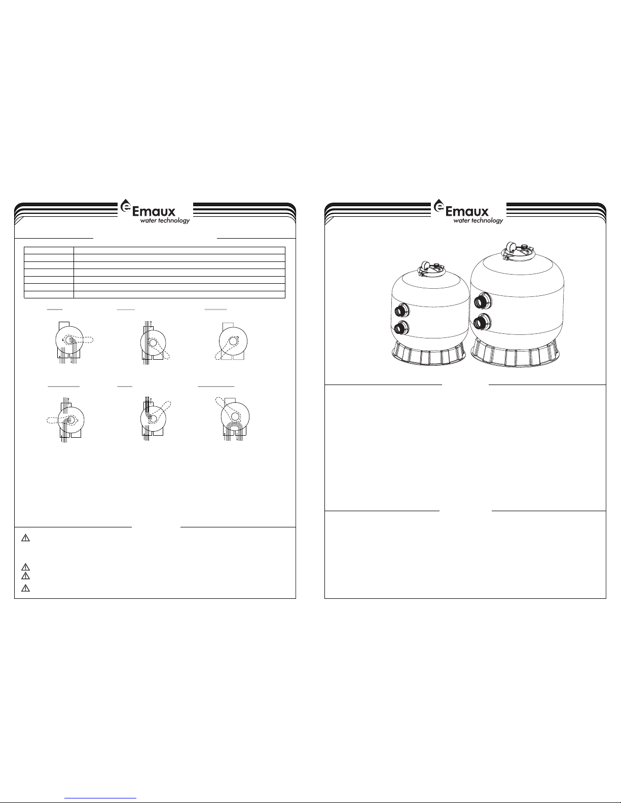
THIS FILTER OPERATES UNDER HIGH PRESSURE. WHEN ANY PART OF THE CIRCULATING
PUMP, FILTER, VALVES, ETC.) IS SERVICED, AIR CAN ENTER THE SYSTEM AND BECOME PRESSURIZED .
PRESSURIZED AIR CAN CAUSE THE LID OR VALVE TO BE BLOWN OFF WHICH CAN RESULT IN SEVERE INJURY,
DEATH, OR PROPERTY DAMAGE.
TURN PUMP OFF BEFORE CHANGING VALVE POSITION.
TO PREVENT DAMAGE TO THE PUMP AND FOR PROPER OPERATION OF THE SYSTEM, CLEAN PUMP STRAINER
AND SKIMMER BASKETS REGULARLY.
DO NOT UNSCREW SCREWS OF FLANGE CLAMP WHILE PUMP IS RUNNING.
SYSTEM (e.g., CLAMP,
WARNING
By-passes filter for circulating water to pool
Used after backwash to flush dirt from valve
Cleaning Filter by reversing the flow
By-passes filter, used for vacuuming to waste or lowering water level
CLOSED Shuts off all flow to filter or pool
RECIRCULATE
WASTE
RINSE
BACKWASH
FILTER
Valve Position
Normal Filtration and Vacuuming
Function
FUNCTIONS OF VALVE POSITIONS
GENERAL
1) Pipe tap boss provided for optional influent pressure gauge.
2) SERVICING VALVE( Stop pump,close gate valve in suction&discharge before proceeding):
a) Set handle in filter position. b) Remove cover screws. c) Lift cover and key assembly out.
TO ASSEMBLE:
1) Place valve key so that wedge opening is at TOP port (handle in Filter psn.). Flat edge of cover screw lug
should align with flat edge of body screw lug.
2) Position cover O'Ring.
3) Secure assembly to body with cover screws. Tighten cover screws evenly and alternately. Do not overtighten.
WASTE
FILTER
BACKWASH
RINSE
WASTE
RECIRCULATE
CLOSED
WASTE WASTE
WASTE WASTE WASTE
IN FLOW
OUT FLOW
IN FLOW
OUT FLOW
IN FLOW
OUT FLOW
IN FLOW
OUT FLOW
IN FLOW
OUT FLOW
IN FLOW
OUT FLOW
Only simple tools (screwdriver and wrenches), plus pipe sealant for plastic adapters, are required to install
andservice the filter.
1) The filter should be placed on a level concrete slab, very firm ground, or equivalent. Position the filter so
that the piping connections, control valve are convenient and accessible for operation and service.
2) Loading the sand media. Filter sand media is loaded through the top opening of the filter.
a) Loosen the clamp lock, remove the transparent lid.
b) Cover the diffuser with the block sand cover.
c) We recommend: add a half tank of water in the tank, then to fill with sand, so that we can protect
the bottom of the filter from the damage caused by excessive shock.
d) Add the right amount of sand, sand surface to smooth.
FUNCTION
The filter uses s pecial filter san d to remove dirt particles from po ol water. The filter sand is loaded into the
filter tank and functions as the permanent dirt removing media.When the control valve is in the FILTER
position, the pool water which contains suspended dirt particles, is p umped th rough you r piping system
and is automati cally directed by the patented filter contro l valve to th e top of the filter tank.As the pool
water is pumped th rough the filter, d irt particles are trapped by the san d bed, and filtered out. The
cleaned Po ol water is returned from the bottom of the filter tan k,through the contro l valve and back to
the pool through the pipin g system. This entire sequence i s continuo us and automatic and provi des for
total recirculation of pool water through your filter and piping System.
After a period of time the accumulated dirt in the filter causes a resistance to flow, and the flow diminishes.
Thismeans it is time to clean your filter. With the control valve in the BACKWASH position, the water flow is
automatically reversed through the filter so that it is directed to the bottom of the tank, up through the sand,
flushingthe previously trapped dirt and debris out the waste line. Once the filter is back-washed of dirt, set
control valve toRINSE position and run pump for about 1/2 to 1 minute, and then to filter, to resume normal
filtering.
NOTE: Turn pump off before changing valve position.
INSTALL/START-UP OF FILTER
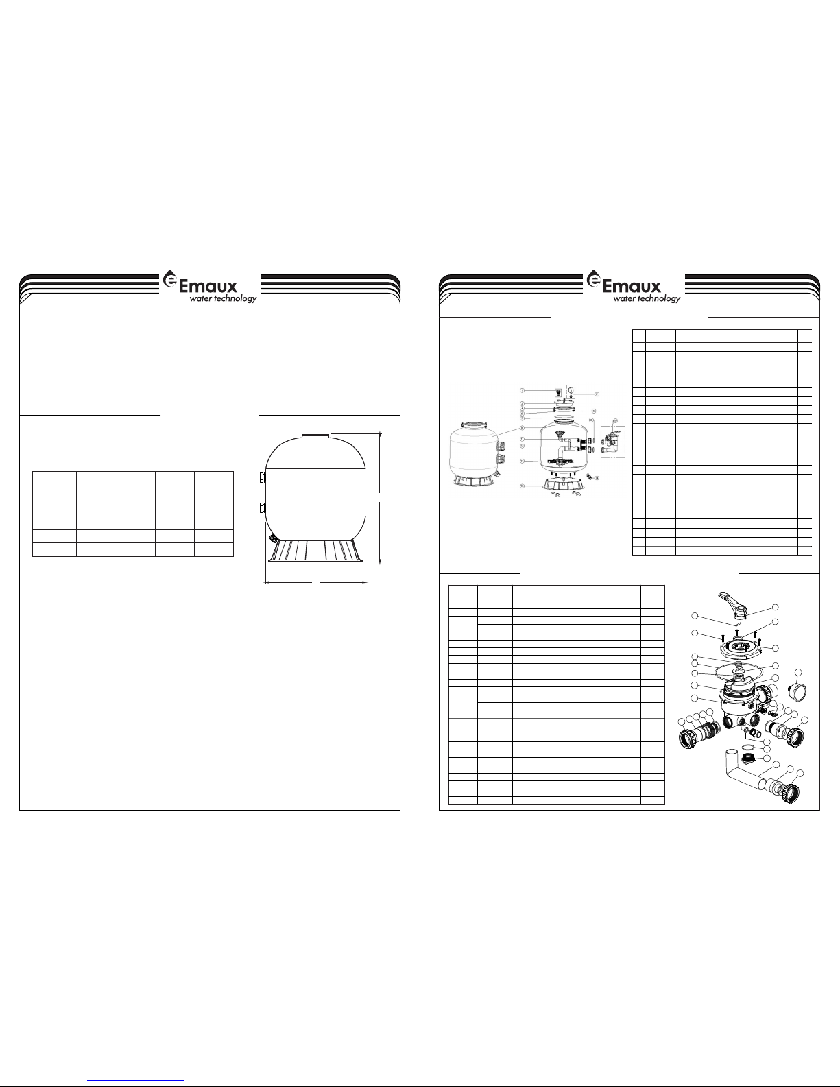
REPLACEMENT PARTS OF MULTIPORT VALVE
2-4
MAIN DIMENSION
3-4
B
A
DIMENSION TABLE
455
535
635
710
Model
A
High
mm
B
Diameter
mm
730
770
850
960
S450
S500
S650
S700
inch
Valve
Sand
kg
1.5 "
1.5 "
45
85
1.5 "
1.5 "
145
210
1
2
3
4
5
6
7
8
9
10
11
12
13
14
15
16
17
18
19
20
21
22
23
24
25
16
16
18
18
Key No .
Part N o.
0101 3002
0301 8008
0118 1001
8928 1203
8928 0107
0105 1010
0201 1022
0118 1002
0201 1002
0301 4001
0102 1001
0231 1002
0105 1021
0111 1048
8902 1303
0601 1032
0202 0013
0105 1022
0101 3017
8928 0104
0105 1023
0105 1193
0117 1002
0105 1013
0201 1003
0117 1153
0201 1139
Prod uct Des cript ion
Qty
1
Hand le (Sma ll)
Pin fo r Handl e
Wash er for Ha ndle
M6×2 5 Screw w ith Nut f or Camb er Lid
M6*3 0 Screw w ith Nut f or Stan dard Li d
1.5" Side Mo unt Val ve Stan dard Li d (Whit e)
O-Ri ng for 1. 5" Valv e Rotor
Wash er for Sp ring
O-Ri ng for 1. 5" Valv e Lid
Spri ng for 1. 5" Simd M ount Va lve
1.5" V alve Ro tor
Spid er Gask et
1.5" S ide Mou nt Valv e Botto m Body (W hite)
Conn ector f or Pres sure Ga uge/S toppe r
O-ri ng
Drai n Plug wi th O-ri ng
Oil Pr essur e Gauge w ith O-r ing (40 Psi)
O-Ri ng
1.5" Union T ale (Wh ite)
1.5" U nion Nu t (Blac k)
Sigh t Glass w ith O-R ing
1.5" S ide Mou nt Valv e Plug (W hite)
1.5" E lbow Tu be (Whi te) 120 mm
1.5" U nion Ad aptor ( Metri c)
1.5" Conne ctor wi th Exte rnal Th read( White )
O-Ri ng φ59×φ53 ×φ3
1.5" Union A dapto r
1
1
1
6
6
1
2
1
1
1
1
1
1
1
1
1
5
1
5
1
1
1
1
3
5
3
1
2
3
4
5
6
7
8
9
10
11
12
13
14
15
16
17
18
19
20
21
22
23
24
25
3) Replace filter coping (with O'ring in place).
a) Mount the O-ring for filter neck, covered with transparent lid.
b) Lock the clamp lock, pay attention to the clamp lock clip on both sides are even.
c) Install the pressure gauge and air release valve to the transparent lid.
d) Connect the pump outlet to the valve inlet,a preliminary combination has completed.
4) Make return to pool pipe connection to control valve opening marked RETURN and complete other
necessary plumbing connections, suction lines to pump, waste, etc.
5) Make electrical connections to pump per pump instructions.
6) To prevent water leakage, be sure all pipe connections are tight.
1) Be sure correct amount of filter media sand is in tank and that all connections have been made and are
secure.
2) Depress control valve handle and rotate to BACKWASH position. (To prevent damage to control valve
seal, always depress handle before turning.)
3) Prime and start pump according to pump instructions (be sure all suction and return lines are open),
allowing the filter tank to fill with water. Once water is flowing out of the waste line, run the pump for at
least 1 minute. The initial back-washing of the filter is recommended to remove any impurities or fine sand
particles in the sand media.
4) Turn pump off and set valve to RINSE position. Start pump and operate until water in sight glass is clear,
about 1/2 to 1 minute.Turn pump off and set valve to FILTER position and restart pump.The filter is now
operating in the normal filter mode, filtering dirt particles from the pool water.
5) Adjust pool suction and return valves to achieve desired flow. Check system and filter for water leaks and
tighten connections, bolts, nuts, as required.
6) Note the initial pressure gauge reading when the filter is clean. (It will vary from pool to pool depending
upon the pump and general piping system.) As the filter removes dirt and impurities from the pool water,
the accumulation in the filter will cause the pressure to rise and flow to diminish. When the pressure gauge
reading is 1.5 bar, higher than the initial "clean" pressure you noted, it is time to backwash the filter (see
BACKWASH under filter and control valve functions).
REPLACEMENT PARTS OF FILTER
Key
No.
Part N o.
Desc ripti on
Qty
1
8901 0701
Air Re lease V alve wi th Orin g
1
2
0601 1032
Maxi mum 40P SI Indi catio n, Stai nless S teel Ca sing
1
3
0120 1022
Lid (T ransp arent )
1
4
0127 1010
Clam p Lock
2
5
0302 1035
M6 Nut
1
6
0301 1095
Scre w
1
7
0201 1134
O-Ri ng for Fi lter Ne ck
1
8
8901 0706
Filt er Tank f or S450
1
8
8901 0705
Filt er Tank f or S500
1
8
8901 0704
Filt er Tank f or S650
1
8
8901 0703
Filt er Tank f or S700
1
9
0201 1003
O-Ri ng for 1. 5" adap tor
2
10
8828 0811W
6 Way 1. 5" Valv e with Pi ping Ki t, 1.5" u nion se t x 3
and pr essur e gauge ( White )
1
11
8901 0708
The In ner Tan k Syste m for S45 0
1118901 0709
The In ner Tan k Syste m for S50 0
1118901 0710
The In ner Tan k Syste m for S65 0
1
11
8901 0711
The In ner Tan k Syste m for S70 0
1
12
0111 1046
1.5" Tank Sy stem Su pport
1130117 2007
Late rals( 115mm )
8
13
0117 2008
Late rals (1 26mm)
8148901 0107
Wate r Drain S et
1
15
0111 1059
16-2 1inch F ilter B ase
1
15
0111 1062
21-2 8inch F ilter B ase
1
 Loading...