

emaux S700B, S900, S800, S700, S1000 User Manual
...
4-4
1-4
Models: S700(B) / S800 / S900
EMFI16 030754
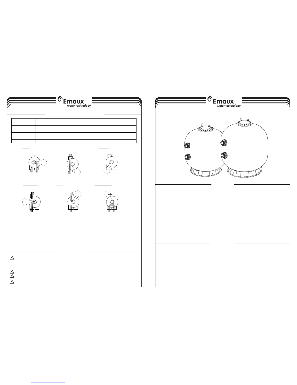
WASTE
FILTER
BACKWASH
RINSE
WASTE
RECIRCULATE
CLOSED
WASTE WASTE
WASTE WASTE WASTE
IN FLOW
OUT FLOW
IN FLOW
OUT FLOW
IN FLOW
OUT FLOW
IN FLOW
OUT FLOW
IN FLOW
OUT FLOW
IN FLOW
OUT FLOW
INSTALLATION
Only simple tools (screwdriver and wrenches), plus pipe sealant for plastic adapters, are required to install and
service the filter.
1) The filter should be placed on a level concrete slab, very firm ground, or equivalent. Position the filter so that
the piping connections, control valve are convenient and accessible for operation and service.
2) Loading the sand media. Filter sand media is loaded through the top opening of the filter.
a) Connect control valve to the filter using pipes with unions
b) Loosen the twelve nuts and washers and remove the filter coping.
c) We recommend filling tank approximately 1/3 way with water to provide a cushion effect when the filter
sand is poured in. This helps protect the under-drain laterals from excessive shock.
d) Carefully pour in correct amount and grade of filter sand. Sand surface should be leveled and should
come to about the middle of the filter tank.
and glues.(see the fig on page4).
By-passes filter for circulating water to pool
Used after backwash to flush dirt from valve
Cleaning Filter by reversing the flow
By-passes filter, used for vacuuming to waste or lowering water level
CLOSED Shuts off all flow to filter or pool
RECIRCULATE
WASTE
RINSE
BACKWASH
FILTER
Valve Position
Normal Filtration and Vacuuming
Function
FUNCTIONS OF VALVE POSITIONS
THIS FILTER OPERATES UNDER HIGH PRESSURE. WHEN ANY PART OF THE CIRCULATING
PUMP, FILTER, VALVES, ETC.) IS SERVICED, AIR CAN ENTER THE SYSTEM AND BECOME PRESSURIZED .
PRESSURIZED AIR CAN CAUSE THE LID OR VALVE TO BE BLOWN OFF WHICH CAN RESULT IN SEVERE INJURY,
DEATH, OR PROPERTY DAMAGE.
TURN PUMP OFF BEFORE CHANGING VALVE POSITION.
TO PREVENT DAMAGE TO THE PUMP AND FOR PROPER OPERATION OF THE SYSTEM, CLEAN PUMP STRAINER
AND SKIMMER BASKETS REGULARLY.
DO NOT UNSCREW SCREWS OF FLANGE CLAMP WHILE PUMP IS RUNNING.
SYSTEM (e.g., CLAMP,
WARNING
GENERAL
1) Pipe tap boss provided for optional influent pressure gauge.
2) SERVICING VALVE( Stop pump,close gate valve in suction&discharge before proceeding):
a) Set handle in filter position. b) Remove cover screws. c) Lift cover and key assembly out.
TO ASSEMBLE:
1) Place valve key so that wedge opening is at TOP port (handle in Filter psn.). Flat edge of cover screw lug
should align with flat edge of body screw lug.
2) Position cover O'Ring.
3) Secure assembly to body with cover screws. Tighten cover screws evenly and alternately. Do not overtighten.
FUNCTION
The filter uses s pecial filter san d to remove dirt p articles from poo l water. The filter sand is loaded i nto the
filter tank and functions as the permanent dirt removing media.When the control valve is in the FILTER
position, the pool water which contains suspended dirt particles, is p umped thr ough you r piping system
and is automati cally directed by the patented filter control valve to the top of the fi lter tank.As t he pool
water is pumped th rough the filter, d irt particles are trapped by the sand bed, and filtered out. T he
cleaned Po ol water is returned from the bottom of the filter tan k,through t he control valve and bac k to
the pool through the pipin g system. This entire sequence i s continuou s and automatic and provid es for
total recirculation of pool water through your filter and piping System.
After a period of time the accumulated dirt in the filter causes a resistance to flow, and the flow diminishes.
Thismeans it is time to clean your filter. With the control valve in the BACKWASH position, the water flow is
automatically reversed through the filter so that it is directed to the bottom of the tank, up through the sand,
flushingthe previously trapped dirt and debris out the waste line. Once the filter is back-washed of dirt, set
control valve toRINSE position and run pump for about 1/2 to 1 minute, and then to filter, to resume normal
filtering.
NOTE: Turn pump off before changing valve position.
2
3
1
4
5
6
7
9
10
11
12
14
16
15
13
17
18
19
20
22
21
24
25
26
23
27
8
2-4
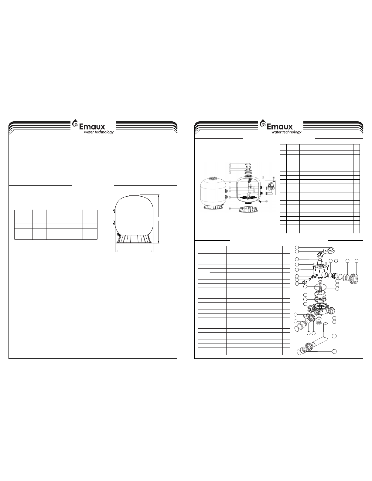
MAIN DIMENSION
REPLACEMENT PARTS OF FILTER
3-4
3 Replace filter coping. Put the twelve nuts and washers onto each of the twelve bolts, then screw all the nuts
on with wrench,ensuring that all nuts are tight.
a
4 Connect pump to control valve opening marked PUMP.
5 Make return to pool pipe connection to control valve opening marked RETURN and complete other
necessary plumbing connections, suction lines to pump, waste, etc.
6 Make electrical connections to pump per pump instructions.
7 To prevent water leakage, be sure all pipe connections are tight.
)
) Carefully screw pressure gauge (with O'ring in place) into tapped hole in the filter coping. Do not over-
tighten.
b) Ensure air relief valve (with O'ring in place) is tight fit to filter coping and turn it easily.
)
)
)
)
B
A
820
920
Model
A
High
mm
B
Diameter
mm
1050
1180
S800
S900
723890
S700(B)
REPLACEMENT PARTS OF MULTIPORT VALVE
Valve Port
Size
Inch
Sand
Kg
2”
2”
2”
355
470
215
Key No .
Part N o.
Prod uct Des cript ion
Qty
1
0101 3003
Hand le (Big )
1
2
0301 8008
Pin fo r Handl e
1
3
0118 1027
Wash er for Ha ndle
1
4
0105 1026
2.0" S ide Mou nt Valv e Squar eness L id (Whi te)
1
5
8928 0301
M6*3 2 Screw w ith Nut
10
6
0111 1048
Conn ector f or Pres sure Ga uge/S toppe r
1
02011139
O-Ri ng
1
7
8902 1303
Drai n Plug wi th O'Ri ng
1
8
0601 1029
Oil Pr essur e Gauge W ith O-r ing (40 psi)
1
9
0202 0016
O-Ri ng for 2. 0"Uni on
8
10
0105 1033
2.0" C onnec tor(W hite)
3
11
0117 1154
2.0" U nion (A /E)
3
12
0105 1032
2.0" U nion Nu t(Whi te)
3130201 1009
O-Ri ng for 2. 0" Valv e Lid
1
14
0118 1002
Wash er for sp ring
1
15
0201 1022
O-Ri ng for 2. 0" Valv e Rotor
2
16
0301 4014
Spri ng
1
17
0102 1002
2.0" V alve Ro tor
1
18
0231 1003
Spid er Gask et
1
19
0105 1027
2.0" S ide Mou nt Valv e Botto m Body (W hite)
1
20
8928 0104
Sigh t Glass W ith O-R ing
1
21
0201 1011
O-Ri ng for Un ion Tal e
1
22
0105 1035
2.0" U nion Ta le (Whi te)
1
23
0101 3034
2.0" U nion Nu t (Blac k)
2
24
0202 0017
O-Ri ng for Pl ug
1
25
0105 1029
2.0" S ide Mou nt Valv e Plug (W hite)
2
26
0105 1195
2.0" E lbow Tu be (Whi te)18 3mm
1
27
0117 1035
2.0" U nion Ad aptor ( Metri c)
1
DIMENSION TABLE
INSTALL/START-UP OF FILTER
1) Be sure correct amount of filter media sand is in tank and that all connections have been made and are
secure.
2) Depress control valve handle and rotate to BACKWASH position. (To prevent damage to control valve
seal, always depress handle before turning.)
3) Prime and start pump according to pump instructions (be sure all suction and return lines are open),
allowing the filter tank to fill with water. Once water is flowing out of the waste line, run the pump for at
least 1 minute. The initial back-washing of the filter is recommended to remove any impurities or fine sand
particles in the sand media.
4) Turn pump off and set valve to RINSE position. Start pump and operate until water in sight glass is clear,
about 1/2 to 1 minute.Turn pump off and set valve to FILTER position and restart pump.The filter is now
operating in the normal filter mode, filtering dirt particles from the pool water.
5) Adjust pool suction and return valves to achieve desired flow. Check system and filter for water leaks and
tighten connections, bolts, nuts, as required.
6) Note the initial pressure gauge reading when the filter is clean. (It will vary from pool to pool depending
upon the pump and general piping system.) As the filter removes dirt and impurities from the pool water,
the accumulation in the filter will cause the pressure to rise and flow to diminish. When the pressure gauge
reading is 1.5 bar, higher than the initial "clean" pressure you noted, it is time to backwash the filter (see
BACKWASH under filter and control valve functions).
NOTE: During initial clean-up of the pool water it may be necessary to backwash frequently due to the unusually
heavy initial dirt load in the water.
Key
No.
Part N o.
Desc ripti on
Qty
1
8901 0601
Nut wi th wash er
12
2
8901 0701
Air Re lease V alve wi th Orin g
130601 1032
Maxi mum 40P SI Indi catio n, Stai nless S teel Ca sing
1
4
0117 2005
Lid (G rey Col our)
1
5
0201 1126
Filt er Neck G asket
1
6
8901 1202
S700 B Filte r Tank
168901 1208
Filt er Tank w ith Bas e for S80 0
1
6
8901 1209
Filt er Tank w ith Bas e for S90 0
1
7
8901 1203
The In ner Tan k Syste m for S70 0 (B)
1
7
8901 1210
The In ner Tan k Syste m for S80 0
178901 1211
The In ner Tan k Syste m for S90 0
1
8
0111 1090
2.0" T ank Sys tem Sup port
190201 1127
O-Ri ng for In let & Out let
2
10
8828 0813W
6 Way 2" V alve wi th Pipi ng Kit, 2 " union s et x 3 and
pres sure ga uge (Wh ite)
1
11
0117 2010
Late rals (1 85mm)
8
11
0117 2011
Late rals (2 33mm)
8128901 0107
Wate r Drain S et
1
13
0111 1062
21-2 8inch F ilter B ase
1
13
0111 2038
32-4 0 inch Fi lter Ba se
1
Notes:11* 01172010 laterals (185mm) is for S700B
11* 01172011 laterals (233mm) is for S800 & S900
 Loading...