

emaux S1000, S1200, S1000C, S1200C, S900 User Manual
...
1-4
Models: S1000(C) / S1200(C)
EMFI15 030248
INSTALLATION
Only simple tools (screwdriver and wrenches), plus pipe sealant for plastic adapters, are required to install and
service the filter.
1) The filter should be placed on a level concrete slab, very firm ground, or equivalent. Position the filter so that
the piping connections, control valve are convenient and accessible for operation and service.
2) Loading the sand media. Filter sand media is loaded through the top opening of the filter.
a) Connect control valve to the filter using pipes with unions
b) Loosen the twelve nuts and washers and remove the filter coping.
c) We recommend filling tank approximately 1/3 way with water to provide a cushion effect when the filter
sand is poured in. This helps protect the under-drain laterals from excessive shock.
d) Carefully pour in correct amount and grade of filter sand. Sand surface should be leveled and should
come to about the middle of the filter tank.
and glues.(see the fig on page4).
FUNCTION
The filter uses s pecial filter san d to remove dirt particles from po ol water. The filter sand is loaded into the
filter tank and functions as the permanent dirt removing media.When the control valve is in the FILTER
position, the pool water which contains suspended dirt particles, is p umped th rough you r piping system
and is automati cally directed by the patented filter contro l valve to the top of the filter tank.As t he pool
water is pumped th rough the filter, d irt particles are trapped by the san d bed, and filtered out. The
cleaned Po ol water is returned from the bottom of the filter tan k,through the contro l valve and back to
the pool through the pipin g system. This entire sequence i s continuo us and automatic and provi des for
total recirculation of pool water through your filter and piping System.
After a period of time the accumulated dirt in the filter causes a resistance to flow, and the flow diminishes.
Thismeans it is time to clean your filter. With the control valve in the BACKWASH position, the water flow is
automatically reversed through the filter so that it is directed to the bottom of the tank, up through the sand,
flushingthe previously trapped dirt and debris out the waste line. Once the filter is back-washed of dirt, set
control valve toRINSE position and run pump for about 1/2 to 1 minute, and then to filter, to resume normal
filtering.
NOTE: Turn pump off before changing valve position.
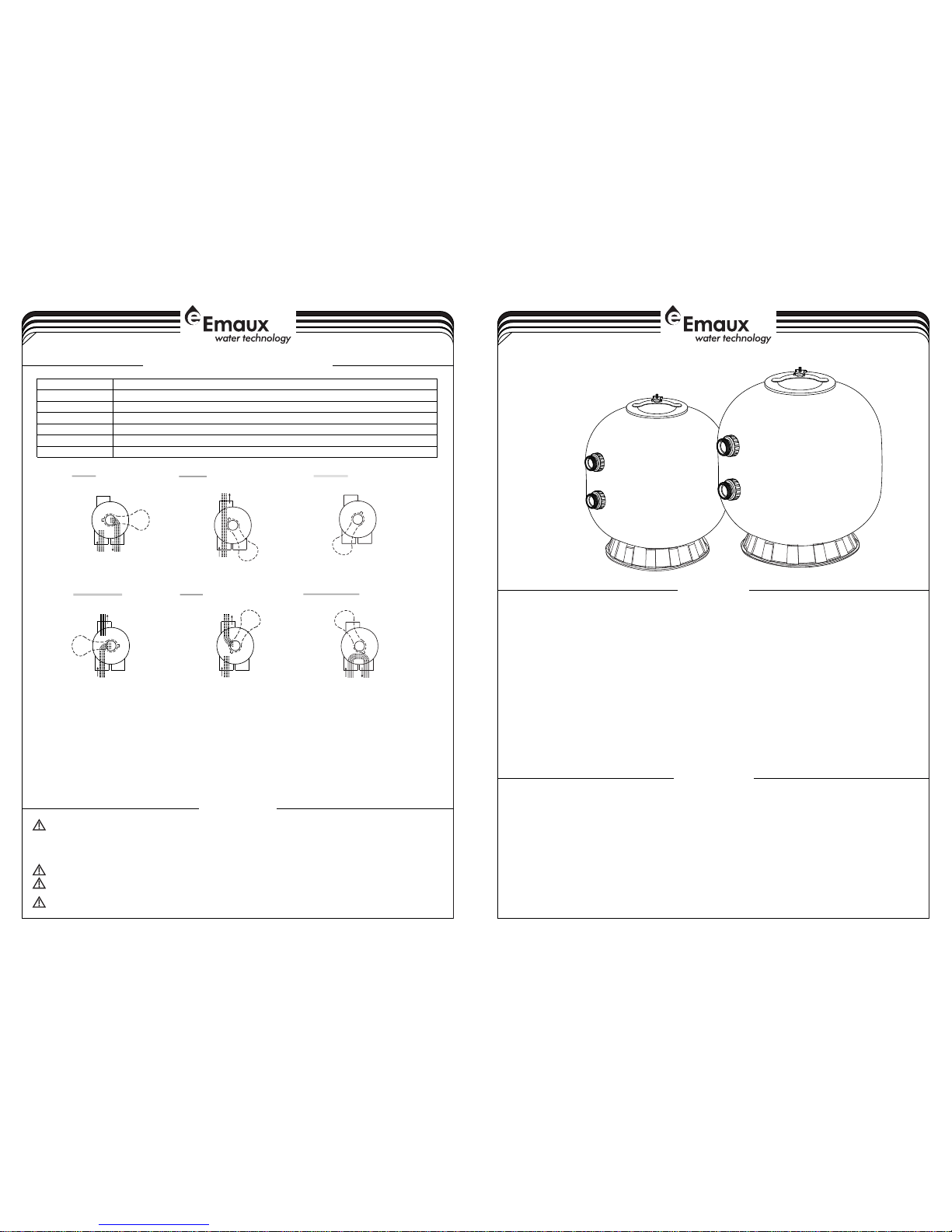
4-4
WASTE
FILTER
BACKWASH
RINSE
WASTE
RECIRCULATE
CLOSED
WASTE WASTE
WASTE WASTE WASTE
IN FLOW
OUT FLOW
IN FLOW
OUT FLOW
IN FLOW
OUT FLOW
IN FLOW
OUT FLOW
IN FLOW
OUT FLOW
IN FLOW
OUT FLOW
By-passes filter for circulating water to pool
Used after backwash to flush dirt from valve
Cleaning Filter by reversing the flow
By-passes filter, used for vacuuming to waste or lowering water level
CLOSED Shuts off all flow to filter or pool
RECIRCULATE
WASTE
RINSE
BACKWASH
FILTER
Valve Position
Normal Filtration and Vacuuming
Function
FUNCTIONS OF VALVE POSITIONS
THIS FILTER OPERATES UNDER HIGH PRESSURE. WHEN ANY PART OF THE CIRCULATING
PUMP, FILTER, VALVES, ETC.) IS SERVICED, AIR CAN ENTER THE SYSTEM AND BECOME PRESSURIZED .
PRESSURIZED AIR CAN CAUSE THE LID OR VALVE TO BE BLOWN OFF WHICH CAN RESULT IN SEVERE INJURY,
DEATH, OR PROPERTY DAMAGE.
TURN PUMP OFF BEFORE CHANGING VALVE POSITION.
TO PREVENT DAMAGE TO THE PUMP AND FOR PROPER OPERATION OF THE SYSTEM, CLEAN PUMP STRAINER
AND SKIMMER BASKETS REGULARLY.
DO NOT UNSCREW SCREWS OF FLANGE CLAMP WHILE PUMP IS RUNNING.
SYSTEM (e.g., CLAMP,
WARNING
GENERAL
1) Pipe tap boss provided for optional influent pressure gauge.
2) SERVICING VALVE( Stop pump,close gate valve in suction&discharge before proceeding):
a) Set handle in filter position. b) Remove cover screws. c) Lift cover and key assembly out.
TO ASSEMBLE:
1) Place valve key so that wedge opening is at TOP port (handle in Filter psn.). Flat edge of cover screw lug
should align with flat edge of body screw lug.
2) Position cover O'Ring.
3) Secure assembly to body with cover screws. Tighten cover screws evenly and alternately. Do not overtighten.
1
2
3
4
5
6
7
8
10
12
14
15
16
1718
21
22
1314151819
23
24
9
1313
11
1920
20
25
9
11
12
10
13
6
8
14
1
2
3
4
7
5
2-4
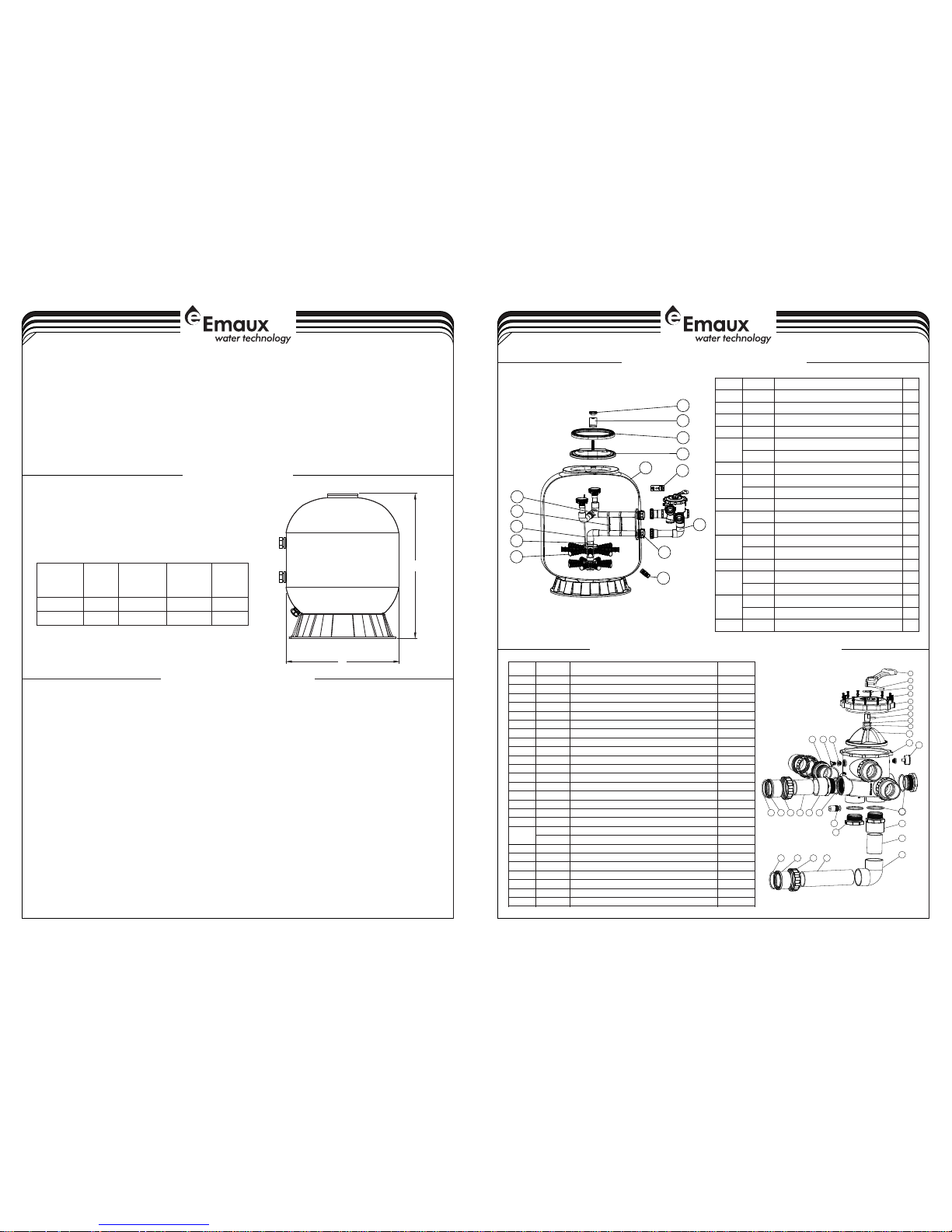
MAIN DIMENSION
REPLACEMENT PARTS OF FILTER
3-4
3) Replace filter coping. Put the twelve nuts and washers onto each of the twelve bolts, then screw all the nuts
on with wrench,ensuring that all nuts are tight.
a)
)
4) Connect pump to control valve opening marked PUMP.
5) Make return to pool pipe connection to control valve opening marked RETURN and complete other
necessary plumbing connections, suction lines to pump, waste, etc.
6) Make electrical connections to pump per pump instructions.
7) To prevent water leakage, be sure all pipe connections are tight.
Carefully screw pressure gauge (with O'ring in place) into tapped hole in the filter coping. Do not over-
tighten.
b Ensure air relief valve (with O'ring in place) is tight fit to filter coping and turn it easily.
B
A
DIMENSION TABLE
1220
Model
A
High
mm
B
Diameter
mm
1410S1200(C)
10201220
S1000(C)
REPLACEMENT PARTS OF MULTIPORT VALVE
Valve Port
Size
Inch
Sand
Kg
2.5”
2.5”
860
620
Item No.
Part No. Product Description Qty
1
2
3
4
5
6
7
8
9
10
11
12
13
14
15
16
17
18
19
20
21
22
23
24
25
0101 3003
0301 8008
0118 1027
8928 1204
0102 1129
0201 0228
0201 1022
0118 1002
0301 4025
8928 0806
0102 1128
0601 1032
0202 0053
0117 1159
0115 0180
0115 0181
0115 0180
0101 3147
0105 1243
0117 1158
0201 0043
0101 3142
8928 0104
0111 1048
8902 1303
0101 3143
Hand le (Bi g)
Pin fo r Handl e
Wash er for Ha ndle( Whi te)
M6* 33 T Scr ew with N ut
2.5 "Sid e Mount V alve St andar d Lid(W hite)
O-R ing for 2 .5" Va lve Lid
O-R ing for 2 .5" Va lve Rot or
Wash er for Sp ring( Whi te)
Spri ng for 2. 5" Si de Moun t Valve
2.5 " Valve R otor Wi th Spid er Gask et
2.5 " Side Mo unt Val ve Bott om Body (Whit e)
Oil Pr essur e Gauge w ith O- ring ( 40P si)
O-R ing for 2 .5"U nion
2.5 " Union ( Whi te)
2.5 " PVC Tub e 90mm
2.5 " Elbow T ube
2.5 " PVC Tub e 270mm
2.5 "Con nector ( Bl ack)
2.5 "Con nector ( wh ite)
2.5 "Uni on (A/ E)( whi te)
O-R ing for U nion Ad aptor
2.5 " Side Mo unt Val ve Plug ( Whi te)
Sigh t Glass W ith O- Ring
Conn ector f or Pres sure Ga uge/S toppe r(Whi te)
Drai n Plug wi th O'R ing( Whit e)
2.5 "Con nector (Whi te)
1
1
1
12
1
1
2
1
1
1
1
1
7
2
2
1
1
2
3
5
5
2
1
2
2
3
Key No .
Part N o.
Prod uct Des cript ion
Qty
1
0111 1100
Star -Shap ed Nut
1
2
0304 2001
Bow- Shape d Metal B ar
1
3
0201 1155
O-Ri ng for Ma nhole
1
4
0116 1006
Manh ole
1
5
8901 1313
S100 0C Filt er Tank W ith Bas e
1
8901 1314
S120 0C Filt er Tank W ith Bas e
1
6
8928 0804
2.5" S ide Mou nt Valv e
1
7
0601 1029
Oil Pr essur e Gauge W ith O-r ing (40 p si)
1
0111 1048
Conn ector f or Pres sure Ga uge/S toppe r
1
8
8928 0117
Conn ector P late Si de Moun t
1
9
8901 1309
S100 0C Top pa rt of the i nner ta nk syst em
1
8901 1310
S120 0CTop p art of th e inner t ank sys tem
1
10
8901 1311
S100 0C Bott om part o f the inn er tank s ystem
1
8901 1312
S120 0C Bott om part o f the inn er tank s ystem
1
11
0111 0030
Tank S ystem S uppor t
2128901 1307
S100 0C Air Ve nt Pipe
1
8901 1308
S120 0C Air Ve nt Pipe
1
13
8901 1319
S100 0C Late rals( 185mm+ 129mm +126m m)
8
8901 1320
S120 0C Late rals( 233mm+ 129mm +126m m)
8
14
8901 0107
Wate r Drain S et
1
INSTALL/START-UP OF FILTER
1) Be sure correct amount of filter media sand is in tank and that all connections have been made and are
secure.
2) Depress control valve handle and rotate to BACKWASH position. (To prevent damage to control valve
seal, always depress handle before turning.)
3) Prime and start pump according to pump instructions (be sure all suction and return lines are open),
allowing the filter tank to fill with water. Once water is flowing out of the waste line, run the pump for at
least 1 minute. The initial back-washing of the filter is recommended to remove any impurities or fine sand
particles in the sand media.
4) Turn pump off and set valve to RINSE position. Start pump and operate until water in sight glass is clear,
about 1/2 to 1 minute.Turn pump off and set valve to FILTER position and restart pump.The filter is now
operating in the normal filter mode, filtering dirt particles from the pool water.
5) Adjust pool suction and return valves to achieve desired flow. Check system and filter for water leaks and
tighten connections, bolts, nuts, as required.
6) Note the initial pressure gauge reading when the filter is clean. (It will vary from pool to pool depending
upon the pump and general piping system.) As the filter removes dirt and impurities from the pool water,
the accumulation in the filter will cause the pressure to rise and flow to diminish. When the pressure gauge
reading is 1.5 bar, higher than the initial "clean" pressure you noted, it is time to backwash the filter (see
BACKWASH under filter and control valve functions).
NOTE: During initial clean-up of the pool water it may be necessary to backwash frequently due to the unusually
heavy initial dirt load in the water.
 Loading...