

emaux NL1200, NL1600, NL1800, NL2300, NL1400 User Manual
...
Thi s man ual pro vid es the nec essar y i nstru ction s to insta ll, use an d mai ntain b obb in woun ded
fil ters. In or der t o o bta in th e bene fits that a re in dicat ed in the c har acter istic s, al l t he instr uctio ns
tha t appea r in this m anual m ust be fo llowe d. This w ill off er a safe a nd long -last ing ins talla tion.
The e quipm ent's s uppli er will p rovid e furth er info rmati on to the u ser whe never i t is need ed.
2. Fi lter' s Chara cteri stics .
The ta nk is made of r esi n o f pol yeste r and gl ass fib er, t ota lly anti corro sive. I nsi de, it con tains
col lecto rs an d dif fuser s mad e of unal ter able plast ic ma teria l (PV C an d A BS), proof agai nst s alt-
2 2
wat er. T hey a re su pplie d for a w orkin g pre ssure of 2.5 kg/ cm to 4 kg /cm and max imum
o
tem perat ure of 43 C. O the r speci ficat ions ca n be supp lied up on requ est.
3 2
Fil trati on ra tes m ay be 20 , 30, 40 an d 50 m /h/ m , depen ding on th e app licat ion a nd the k ind o f
fil trati on elem ents th at have b een sel ected . Rate 50 i s not adv isabl e in publ ic pool s.
1. De scrip tion.
The se fi lters have been desi gne d to provi de wa ter filt ratio n in pools and wat er pa rks, also for all
wat er tre atmen ts th at r equir e the elimi natio n of su spend ed ma tte r usi ng t he pr ope r redu ction of
fil trati on elem ent.
Apa rt from the fi lte r i tself , f iltra tion and de pur ation pr ocess in clude so me poi nts that mu st be
tak en in to ac count as t hey can influ ence the corr ect f ilter oper ation . The se would be c hemic al
wat er trea tment , pump eq uipme nt, pip e segme nts and g enera l hydra ulic de sign.
Whe n pub lic p ool s are conc ern ed, t he cu rrent rule s i n eac h c ountr y sho uld be o bserv ed, a s t he
ins talla tion mu st foll ow them .
The filt ratio n qua lit y dep ends on di ffe rent param eters as d ept h of filtr ation bed, char act erist ics,
qua lity an d grade o f filtr ation m edia, e tc, as we ll as fil trati on rate .
To ch ange sa nd or fil trati on elem ents, p rocee d as foll ows:
·Rem ove top l id.
· Dra in filt er's wa ter and s and thr ough th e lower d raina ge hole .
·If th ere is ro om, san d can be re moved t hroug h the man hole.
·To re fill th e filte r with sa nd, fol low the i nstru ction s given i n start ing.
Thi s fil ter h as be en m anu factu red u sing the b est h igh t echno logy mate ria ls an d man ufact uring
pro cess, g oing th rough s trict q ualit y tests o n mater ials, f inish es and pe rform ance.
All those bum ps, ri ps and bre akage s caus ed by a n in adequ ate us e of the produ ct or b y ig norin g
our r ecomm endat ions ar e not inc luded i n this gu arant ee.
The co rre ct perfo rmanc e o f the filt er's tan k a nd the int ernal co mpone nts is guara nteed fo r 1
yea r.
The se gua rante es inclu de o nly the rep lac ement of def ectiv e p art s. Furth er c harge s, as tho se
wor ks made b y third p artie s, comp ensat ions, e tc, wil l not be ac cepte d by the ma nufac turer .
If the equi pment has bee n st opped dur ing a lo ng p eriod of time , it is advi sable to empt y th e
wat er filt er.
·If th e filte r is situ ated ou tside , it is adv isabl e to pain t it with a s uitab le prod uct eve ry two ye ars.
· In stan dar d fi lters , Pre ssure and tem per ature spe cif icati ons mus t no t be exce eded. Cont act
our t echni cal dep artme nt if you h ave any d oubt ab out the u se of our f ilter .
2
· Du ring the wash ing proce ss, press ure must nev er exce ed 1 kg/ cm for filt ers wit h p lat e wi th
noz zles.
·Opt ional ly, hig h perfo rmanc e filte rs can al so be del ivere d with la teral m anhol e and sig ht glas s,
As we ll as spe cial in ner fin ishes o f high ma inten ance qu ality a nd chem ical re sista nce.
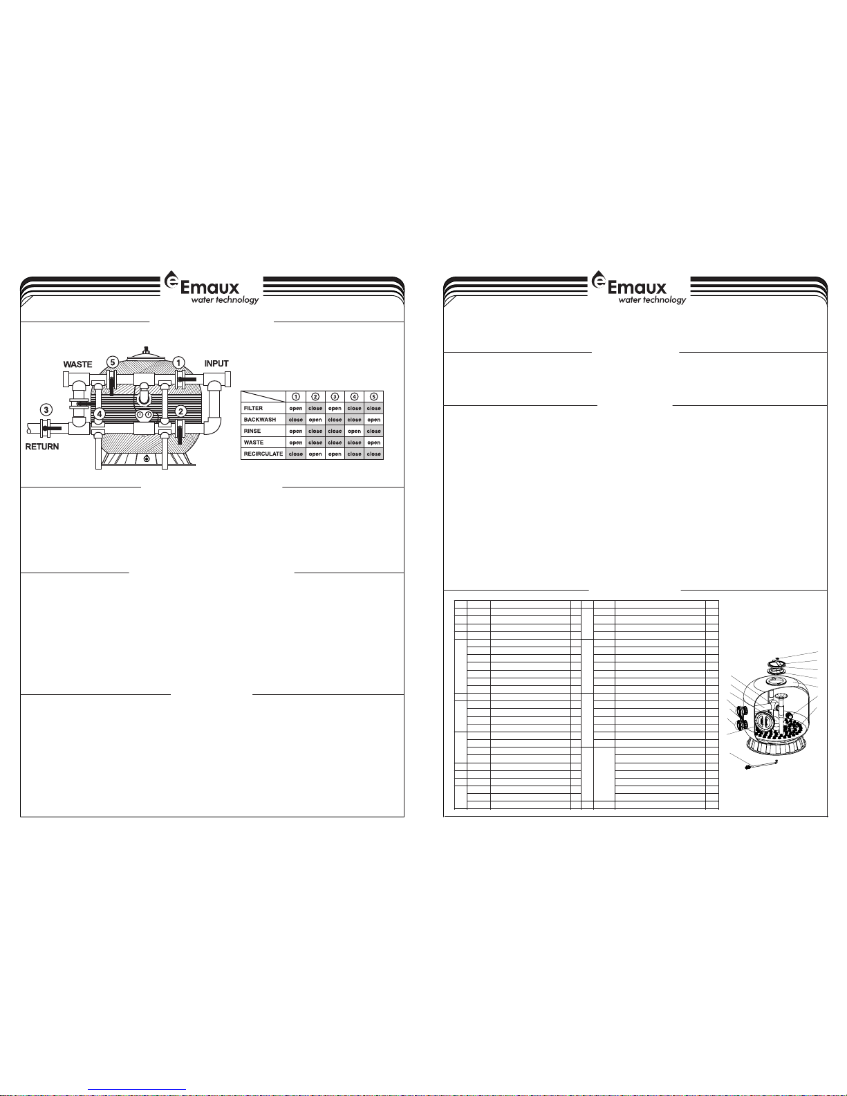
It has to be do ne w it h th e pu mp s to pp ed a nd v al ve s in p os it io n.
Models: NL1200 / NL1400 NL1600 NL1800 NL2000 NL2300 NL2500/ / / / /
INTRODUCTION
SAND FILTER
DESCRIPTION
SPECIFICATIONS
WORKING PROCESS
EMPTYING OF FILTER'S SAND
OTHER RECOMMENDATIONS
GUARANTEE
4-4
1-4
1
2
4
3
6
5
7
8
9
10
11
12
13
14
15
Item
Part No .
Descr iptio n
Qty
Item
Part No .
Descr iptio n
Qty
1
01111 100
Star- Shaped Nut
11289012 821
NL180 0-2. 5/4bar Fi lter Ta nk With B ase
1203042 001
Bow- Shaped Meta l Bar
1
89012 847
NL200 0-2. 5/4bar Fi lter Ta nk With B ase
1302011 155
O-Ri ng for Ma nhole
1
89012 832
NL230 0-2. 5/4bar Fi lter Ta nk With B ase
1401161 006
Manho le189012 833
NL250 0-2. 5/4bar Fi lter Ta nk With B ase
1589012 803
NL120 0-2. 5/4bar Ai r Venti ng Pipe
11389012 804
NL120 0-2. 5/4bar up per fil trati on syst em
1
89012 809
NL140 0-2. 5/4bar Ai r Venti ng Pipe
1
89012 810
NL140 0-2. 5/4bar up per fil trati on syst em
1
89012 814
NL160 0-2. 5/4bar Ai r Venti ng Pipe
1
89012 815
NL160 0-2. 5/4bar up per fil trati on syst em
1
89012 819
NL180 0-2. 5/4bar Ai r Venti ng Pipe
1
89012 823
NL180 0-2. 5/4bar up per fil trati on syst em
1
89012 820
NL200 0-2. 5/4bar Ai r Venti ng Pipe
1
89012 824
NL200 0-2. 5/4bar up per fil trati on syst em
1
89012 830
NL230 0-2. 5/4bar Ai r Venti ng Pipe
1
89012 834
NL230 0-2. 5/4bar up per fil trati on syst em
1
89012 831
NL250 0-2. 5/4bar Ai r Venti ng Pipe
1
89012 835
NL250 0-2. 5/4bar up per fil trati on syst em
1
6
89012 842
Sight G lass
11489012 805
NL120 0-2. 5/4bar lo wer fil trati on syst em
1
7
89012 848
NL120 0-2. 5/4. 0bar Up per fla nge
1
89012 811
NL140 0-2. 5/4bar lo wer fil trati on syst em
1
89012 849
NL140 0/16 00-2 .5/4 bar Upp er flan ge
1
89012 816
NL160 0-2. 5/4bar lo wer fil trati on syst em
1
89012 850
NL180 0/20 00-2 .5/4 bar Upp er flan ge
1
89012 825
NL180 0-2. 5/4bar lo wer fil trati on syst em
1
89012 851
NL230 0/25 00-2 .5/4 bar Upp er flan ge
1
89012 826
NL200 0-2. 5/4bar lo wer fil trati on syst em
1889012 852
NL120 0-2. 5/4b ar lowe r flang e
1
89012 836
NL230 0-2. 5/4bar lo wer fil trati on syst em
1
89012 853
NL140 0/16 00-2 .5/4 bar low er flan ge
1
89012 837
NL250 0-2. 5/4bar lo wer fil trati on syst em
1
89012 854
NL180 0/20 00-2 .5/4 bar low er flan ge
1
15
89012 856
NL120 0-2. 5/4bar No zzles
48
89012 855
NL230 0/25 00-2 .5/4 bar low er flan ge
1
NL140 0-2. 5/4bar No zzles
66
9
89012 843
NL Manh ole Cov er
1
NL160 0-2. 5/4bar No zzles
66
10
89012 857
Dash bo ard1NL180 0-2. 5/4bar No zzles
69
11
89012 858
Nozzl ed late ral
1
NL200 0-2. 5/4bar No zzles
1101289012 808
NL120 0-2. 5/4b ar Filt er Tank W ith Bas e
1
NL230 0-2. 5/4bar No zzles
150
89012 813
NL140 0-2. 5/4b ar Filt er Tank W ith Bas e
1
NL250 0-2. 5/4bar No zzles
195
89012 818
NL160 0-2. 5/4b ar Filt er Tank W ith Bas e
1
EMFI16 05051 0

2-4
3-4
Bef ore fil lin g f ilter s wit h san d or ot her fi ltrat ion ele men ts, it is adv isabl e to ch eck t he in ter nal
col lecto rs to mak e sure th at they h ave not b een dam aged du ring tr anspo rt or ins talla tion.
Aft erwar ds, fi ll the fil ters w ith wa ter and ma ke hyd rau lic te st. Th us, yo u wi ll mak e sure tha t ther e is
no le ak and th at the eq uipme nt work s prope rly.
The n stop t he pump s, ope n ea ch f ilt er's l id ( the fil ter mus t not be emp tied w ith out op eni ng the l id,
as i t coul d co llaps e) and e mpty h alf th e wate r th at eac h fi lter c ont ains. Then, sta rt fil ling t he f ilter
wit h sand o r other fil trati on ele men ts, tak ing in to acco unt th at f irs t of all y ou mus t pu t gra vel up t o
the c ollec tor arm s (10 cm ap prox. )
Thi s mus t be done very care fully in o rder to a voi d any dam age in the lowe r com ponen ts o f t he
fil ter. Wh en the fi lter is b eing fi lled wi th sand , this mu st be car efull y sprea d over th e surfa ce.
Onc e the filt er is fu ll with the filt ratio n ele men ts cl ean t he li d a nd th e i nner par t of the manh ole.
Thi s will pr event a ny debr is and pa rticl es of san d affec ting th e seal of t he join t.
Int roduc e the lid in the m anhol e, le aving it l eve led a nd ce ntere d. Th e l id mu st be supp ort ed by
the h andle , as this w ill avo id that i t could f all int o the tan k and dam age any o f its par ts.
Put t he brid ge in the p ositi on show n and tig hten ma nuall y the whe el.
To ac hieve a pro per sea l, you d o not hav e to tig hte n exces sivel y the wh eel , as thi s cou ld dam age
the l id. The p ressu re itse lf will i mprov e the sea l.
Whe n the filt er is un der pres sure, it is norm al th at wh eel and bri dge r emain sepa rat ed. Y ou mu st
not tight en the wheel again when t he fil ter is under press ure, b ecaus e when the pu mps st op, th e
lid c ould be d amage d or bloc ked.
Onc e the fi lter ha s been c omple tely fi lled w ith wat er, st art t he perf orman ce of in stall ation ,
ven ting man ual ly to e limin ate all the air th at cou ld be insi de the filte r, as the pr ese nce of air
imp airs th e filte r perfo rmanc e.
If a va cuum forms in th e fi lters , it i s nec ess ary to inst all do uble eff ect su ction cups , thes e wil l a lso
act a s autom atic ai r purif iers an d would a void th at the ta nk coul d colla pse.
Aft er this , the fil ter has b een rea dy for wo rking p roces s.
1.1 )
It is a ccept able to p lace th e filte rs unde r the wat er leve l.
Howe ver if vacuu m occu rs in the inst alla tion, suc tion cups mu st be ins talled in th e lids t o avo id th at
dep ressi on coul d colla pse the f ilter 's tank s.
Filt ers must be si tuat ed so that the ir bas es are pe rfectl y leve l and com pletely s uppo rted by the f loor.
The l ocati on must b e of appr opria te size t o allow m ainte nance p eriod ic over hauls a nd othe r
wo rk. Addi tiona lly the room must pro vide a drain to allow , in case of accident , evacuat ion of water
flowi ng from an y tube, filte r, pump, etc. thi s will avoid risk of dama ges in the electr ical i nsta llat ions
(p um ps , electric panels, etc. )
1.2 )
The m anome ter pan el had be en inst alled i n the fil ter. In p ools fi lters , the usu al pres sures w hen the
fil ter is cl ean are :
2
· Inl et pres sure: 0 .8-1 Kg /cm .
2
· Out let pre ssure : 0.4-0 .6 Kg/c m .
2
Whe n the dif feren tial pr essur e betwe en the tw o manom eters i s 1 Kg/cm o r highe r, back wash
mus t be carr ied out .
Fil ters lo catio n.
Man omete rs.
INST AL LATIO N
STARTING
INN ER PART O F
MAN HOLE
HAN DLE
BRI DGE
WHE EL
LID
1) Filter installation
Filters are delivered properly packed and ready in order to
facilitate unloading and transport using fork-lift truck,
crane, etc. It is very important to make sure that the filters
have not suffered bumps during transport.
To obtain a correct filter installation, the following stages must
be observed:
· Install filters in their final location.
· Install correctly the butterfly valves in the filters.
· To connect with the flange of the filter, use PN1.6MPa or
Class E 15bar PVC pipe.
· Install butterfly valves supports and regulate them correctly
(height, etc.)
· Connect butterfly valves with the pipe of the pumps, return
pipes and drain.
· Check the inner parts of each filter (collectors, top
diffusers).
· Fill the filters with water.
· Empty half the water and add the filtration element
(gravel, sand and/or anthracite), etc.
Instrument Panel installation:
· Before running the filter, drill a Φ11.4 diameter hole in the
filter's return pipe and drain that connects to the water
inlet and outlet.(Figure 1, Figure 2)
· Tap a 1/4" thread to the hole with Teflon tape. (Figure 3,
Figure 4)
· Twine the connection head with Teflon tape, fix to 1/4"
thread and connect to the direct head and the valve of
the panel.(Figure 5, Figure 6, Figure 7)
Caution:
· Tap with PN1.6Mpa or Class E 15bar PVC pipe.
Fig ure 1 Fig ure 2
Fig ure 3 Fig ure 4
Fig ure 5 Fig ure 6
Fig ure 7
INL ET
OUT LET
 Loading...