

emaux MFS20, MFS27A, MFS27, MFS24, MFS17 User Manual
...
FILTER MAX SERIES
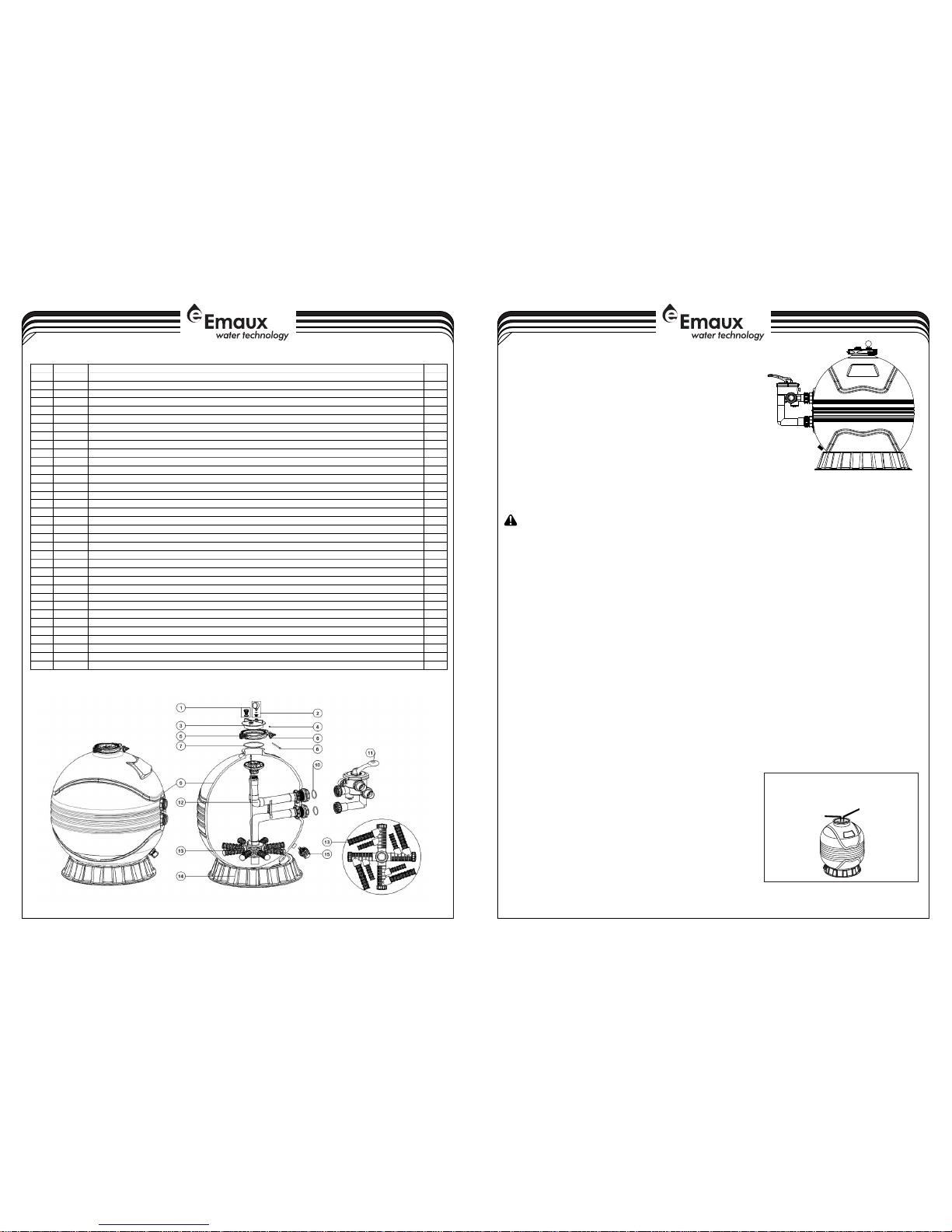
PAR TS FOR FI LTER MA X FILTE R
MODEL: MFS17 / MFS20 / MFS24 / MFS27A / MFS27 /
MFS31A / MFS31 / MFS35
1-4
4-4
EMFI16 03055 5
Your Emaux “Filter Max” Filter is a high performance corrosion-proof filter that has superior flow characteristics that is with the
ease of operation. Everything is made simple from installation, operation to the maintenance of the filter. Your “Filter Max”
filter will be your pool filtration partner that provides clear water with the least maintenance hassle and care.
WAR NING: B EFORE I NSTAL LATIO N BE SURE T O READ AL L INSTR UCTIO NS AND WA RNING S
CAR EFULL Y. KEEP T HIS USE R MANUA L FOR FUT URE REF ERENC E.
HOW I T WORKS
The Filte r use s spec ial s and t o remo ve di rt par ticle s fro m pool wate r. Fil ter s and is load ed int o the filt er tan k to
act a s the fil trati on medi a. The po ol wate r which c ontai ns dirt p artic les is pu mped th rough y our pip ing sys tem to
the filte r via the f ilter contr ol va lve. A s poo l wate r pas ses th rough the f ilter , dir t part icles will be ca ught b y the
san d bed and f ilter ed ou t. Th e cle aned p ool w ater is re turne d from the botto m of t he Fi lter Tank, thro ugh th e
con trol va lve and b ack to t he pool t hroug h your pi ping sy stem. T he enti re pro cess is c ontin uous an d autom atic.
It is t his pro cess th at prov ides th e filtr ation a nd circ ulati on of wat er in you r pool.
Wit h the fi ltrat ion pro cess, d irt wil l accu mulat e and bec omes s atura ted in th e filt er tank . Press ure in t he tank will
inc rease an d t he resi stanc e o f w ater fl ow will occ ur. This m eans it is ti me to clean (b ackwa sh) you r f ilter .
Ano ther indic ation to know when to clean (ba ckwas h) t he fi lter is b y ch eckin g th e pre ssure gau ge re ading .
Bac kwash o perat ion sho uld be pe rform ed when t he pres sure in creas es by 10p si abov e the pre ssure w hen it wa s
cle an. Ty pical ly a c lean f ilter will run at 10 to 15ps i, so t ake n ote of the p ressu re gau ge rea ding when t he fil ter
was inst alled . Wh en th e pre ssure rea ches appro ximat ely 2 0 to 25ps i or 50% incre ase f rom the c lean readi ng,
pro ceed to t he Back wash op erati on.
WAR NING: t urn off t he pump b efore s witch ing the c ontro l valve h andle .
To p erfor m the B ackwa sh ope ratio n, po sitio n the h andle on the contr ol val ve to “Back wash” , the w ater f low is
aut omati cally rever sed t hroug h the filte r so t he wa ter i s dire cted from t he bo ttom o f the tank , up t hroug h the
san d, flus hing th e trapp ed dirt a nd debr is
out o f the wa ste li ne. The durat ion of t he back wash o perat ion wil l depen ds on ho w dirt y your f ilter i s. Che ck the
sig ht gl ass t o see when the water beco mes c lear. It i s rec ommen ded t hat t he ba ckwas h sho uld b e at l east 2
min utes lo ng.
Onc e the back wash opera tion had b een c omple ted, the f ilter shou ld go thro ugh the p roces s of “Rins e” an d
the n back to “ Filte r”. To pe rform t he diff erent o perat ions, p ositi on the ha ndle on t he cont rol val ve as ind icate d.
MFS 17
MFS 27 , MFS3 1A, MFS 31, MFS 35
, MFS 20 , MFS2 4 , MFS27 A
1. Pl ace on ta nk
ope ning.
2. Ad d water t o
cov er late rals
and a dd sand .
INS TALLA TION
Ins talla tion had be en made si mple, th e o nly tool s n eeded i s a
scr ewdri ver and p ipe sea lant fo r plast ic.
The filt er sh ould be in stall ed as clos e to t he po ol as poss ible, but
kee p a dista nce of at l east 5 f eet (1. 5m). Lo cate th e Filte r on rigi d,
lev el surf ace, pre ferab ly in a dry, s haded , and wel l-vent ilate d
are a. Pri or to ins talla tion g ive c onsid erati on to the foll owing :
Pos ition o f sucti on, re turn, a nd wast e conne ction s. Acc ess for
bac kwash ing o perat ion a nd se rvici ng; p rotec tion f rom s un, r ain,
spl ashin g, etc; Drain age of fi lter r oom; Ve ntila tion an d prote ction
of th e motor .
1)F ill th e tank w ith wat er to t he leve l that cove rs the late rals
(cr epina s), or about 1/ 3 o f th e t ank heig ht i s r ecomm ended .
Thi s wil l av oid d amage s to the later als ( crepi nas) by t he fo rce
of th e sand wh en pour ing int o the fil ter.
Key No .
Part N o.
Desc ripti on
Qty
1
8901 0701
Air Re lease V alve wi th Orin g
1
2
0602 1013
Plas tic Pre ssure G auge wi th O-ri ng
1
3
0120 1022
Lid (T ransp arent )
1
4
0302 1035
M6 Nut
1
5
8901 2512
Clam p Kit16
0111 1101
Star -Shap ed Nut
1
7
0201 0007
O-Ri ng
1
8
0301 1166
M6×1 10mm Sc rews
1
9
8901 2606
Filt er Tank f or MFS1 7
1
9
8901 2607
Filt er Tank f or MFS2 0
1
9
8901 2608
Filt er Tank f or MFS2 4
198901 2609
Filt er Tank f or MFS2 7A
1
9
8901 2620
Filt er Tank f or MFS2 7
1
9
8901 2610
Filt er Tank f or MFS3 1A
1
9
8901 2621
Filt er Tank f or MFS3 1
1
9
8901 2622
Filt er Tank f or MFS3 5
1
10
0201 1003
O-Ri ng for 1. 5" adap tor
2100202 0016
O-Ri ng for Co nnect or
2
11
8828 0811B
6 Way 1. 5" Valv e with Pi ping Ki t, 1.5" u nion se t x 3 and pre ssure g auge (B lack)
1
11
8828 0812B
6 Way 2" V alve wi th Pipi ng Kit, 2 " union s et x 3 and pr essur e gauge ( Black )
1
12
8901 2601
The In ner Tan k Syste m for MFS 17
1
12
8901 2602
The In ner Tan k Syste m for MFS 20
1
12
8901 2603
The In ner Tan k Syste m for MFS 24
1
12
8901 2604
The In ner Tan k Syste m for MFS 27A
1
12
8901 2605
The In ner Tan k Syste m for MFS 31A
1128901 2617
The In ner Tan k Syste m for MFS 27
1
12
8901 2618
The In ner Tan k Syste m for MFS 31
1
12
8901 2619
The In ner Tan k Syste m for MFS 35
1
13*
0117 2007
Late rals( 115mm )
*
13*
0117 2008
Late rals (1 26mm)
*
13*
0117 2010
Late rals (1 85mm)
*140111 1059
16-2 1inch F ilter B ase
1
14
0111 1062
21-2 8inch F ilter B ase
1
14
0111 2037
31-3 5inch F ilter B ase
1158901 1601
Wate r Drain S et
1
Note s:13* M FS17/ M FS20 sh ould ha ve 8pcs o f later al (115 mm)
13* MF S24/ MF S27A/ M FS31A s hould h ave 8pc s of late ral (12 6mm)
13* MF S27/ MF S31/ MF S35 sho uld hav e 4 pcs of la teral ( 115mm ) and 4pc s of late ral (18 5mm)

SUG GESTE D POOL CH EMIST RY LEVE LS
ACT ION REQ UIRED T O CORRE CT POOL C HEMIS TRY
TO RA ISE
Add S oda Ash
Add Sodium Bicarbonate
Add Chlorine Chemical
Add Chlorine Chemical
Add S tabil izer
TO LO WER
Add M uriat ic Acid o r Sodiu m Bisul phate
Add M uriat ic Acid
No ac tion- chlor ine wil l natur ally di ssipa te
No ac tion- chlor ine wil l natur ally di ssipa te
Dil ution -part ially dr ain&r efill p ool with w ater
tha t has not b een tre ated wi th Cyan uric Ac id.
TYP ICAL IN STALL ATION
POO L CHEMI STRY GU IDELI NES
SPE CIFIC ATION S
3-4
2-4
2)P our the r ecomm ended a mount o f sand i nto the t ank, ma king su re
tha t the cen tre-p ipe rem ains ce ntred a nd vert ical.
3) Le vel the s urfac e of the sa nd upon c omple tion.
4)R emove t he Sand F ill Cov er.
5)C arefu lly rem ove all sa nd p artic les fro m th e va lve mou nting
sur face.
6)P lace th e O-rin g into th e groov e on the ta nk.
7)L ower t he Mul tipor t Cont rol V alve c arefu lly in to pos ition so th at its
und ersid e e ngage s w ith the ce ntre- pipe. Ro tate the va lve unti l
the i nlet is a pprox imate ly in lin e with th e pump.
8)P lace the cl amp s et ar ound t he ta nk an d the valve . Sec ure u sing
the s crew pr ovide d.
9)F irmly tap wit h a ru bber m allet ou tside of t he cl amps a s you
tig hten th e screw .
10) Tight en the sc rew unt il the M ultip ort Con trol Va lve is p roper ly
ass emble d to crea te a wate r tight s eal. Do n ot over t ighte n.
11) Insta ll the p ressu re gaug e into t he thre aded o penin g on the M ultip ort Con trol
Val ve.
12) Insta ll the un ion set s and the b ackwa sh unio n set.
13) Conne ct pump t o the con trol va lve ope ning ma rked “P UMP”.
14) Make retu rn to poo l pip e con necti on to con trol val ve ope ning mar ked
“RE TURN” .
15) Conne ct the wa ste wat er pipe t o the con trol va lve ope ning ma rked “W ASTE” .
16) To prev ent wat er leak age, be s ure all p ipe con necti ons are t ight.
17) Prior to st artin g the f iltra tion p roces s by tur ning o n the p ump, we hig hly
rec ommen d th at you read thr ough the pum p in struc tion manu al to e nsure
pro per ins talla tion an d to avoi d the ris k of elec tric sh ock.
FIG URE3. -Clam p Insta llati on
tap w ith a
rub ber
mal let and
tig hten th e
scr ews.
STA RT-UP P ROCED URE
1)B e sure the co rrect amoun t of fi lter s and me dia is in the tank a nd all conn ectio ns hav e been made a nd are
sec ure.
2)T urn the C ontro l Valve h andle t o the “Ba ckwas h” posi tion. P ress th e handl e downw ard bef ore tur ning.
3)S tart th e pump ac cordi ng to pum p instr uctio n manua l (be sur e all suc tion an d retur n lines a re open ).
4)O nce wa ter fl ow is s teady out th e was te lin e, run the pu mp for at lea st 2 mi nutes . The initi al bac kwash ing of
the f ilter i s recom mende d to remo ve any im purit ies or fi ne sand p artic les in th e sand me dia.
5)T urn t he p ump o ff a nd se t th e con trol valv e to RINS E pos ition . St art p ump and o perat e un til w ater in s ight
gla ss is clear abou t ½ to 1 min ute. Turn p ump o ff, se t val ve to FILTE R pos ition and r estar t pump . You r fil ter is
now o perat ing in th e norma l filte r mode, f ilter ing par ticle s and dir t from th e pool wa ter.
6)T ake not e of the in itial p ressu re gaug e readi ng for fu ture re feren ce. Var iatio n may occ ur from p ool to po ol.
7)A djust pool suct ion a nd re turn valve s to achie ve de sired flow . Che ck sy stem and filte r for wate r lea ks an d
tig hten co nnect ions, b olts, n uts as re quire d.
NOT E: Du ring the init ial c lean- up o f the poo l wat er, it m ay be nec essar y to back wash frequ ently due to the
unu suall y heavy i nitia l dirt lo ad in the w ater.
IMP ORTAN T: To prev ent unne cessa ry stra in on pipin g syste m a nd cont rol valv e, alwa ys turn off t he pump
bef ore cha nging the ope ratio n of the contr ol valv e. To pr event damag e to the p ump an d filte r and fo r prop er
ope ratio n of the sy stem, c lean pu mp stra iner (b asket ) and ski mmer ba sket( s) regu larly .
MUL TIPOR T CONTR OL VALV E FUNCT IONS: FIL TER giv es down ward fl ow thro ugh the f ilter b ed. Thi s posit ion can a lso be us ed for va cuumi ng.
BAC KWASH give s upwa rd fl ow th rough the f ilter bed that r emove s the dirt from the s and a nd ca rries it to the
was te.
WAS TE is f or pum ping w ater f rom th e pool. It all ows th e flow from t he pum p to by pass t he fil ter an d go di rectl y
to th e waste . You can a lso use t his pos ition t o vacuu m heavy c oncen trati on of deb ris.
REC IRCUL ATE byp asses t he filt er to cir culat e water t hroug h the poo l syste m.
RIN SE give s a dow nward f low th at set tles th e filt er bed a fter b ackwa shing a nd car ries a ny rema ining loose d irt
to th e waste .
CLO SED pre vents o nly bac kflow o f water f rom poo l durin g pump ma inten ance.
To WI NTERI SE, set the con trol va lve ha ndle in t he mid dle bet ween RI NSE and FILTE R. This w ill al low air t o leav e or
ent er the ta nk to hel p primi ng and dr ainin g. Only t o be used w hen the p ump is of f.
VAC UUMIN G THE POO L
Lig ht Soil : set the c ontro l valve t o FILTE R posit ion.
Hea vy Soil : set the c ontro l valve t o WASTE p ositi on.
WIN TERRI SING
Bac kwash the fi lter f or at l east t hirty minut es bef ore cl osing down t he poo l for w inter ising . This will c lean t he fil ter be d
tho rough ly.
1)D rain th e filte r tank by r emovi ng the dr ain cap a t the bas e of the fi lter ta nk. Lea ve the ca p off dur ing win ter.
2)S et the co ntrol v alve ha ndle be tween t he RINS E and FIL TER. Th is will l ift the h andle a nd help w ith the d raini ng proc ess
by al lowin g air to en ter int o the tan k.
3)U nscre w the pre ssure g auge fr om the co ntrol v alve an d store t he gaug e indoo r.
4)D rain an d winte rise pu mp acco rding t o pump in struc tions .
5)R epair s shou ld be m ade du ring the of f-sea son wh en the best servi ce is a vaila ble, do not leav e them until the ne xt
sea son.
TRO UBLE SH OOTIN G
SAN D ENTER ING THE P OOL
San d too sm all; F low to o high ; Sand bed ca lcifi ed; Bro ken La teral s; Loo se cen tre-p ipe; T oo muc h sand ; Contr ol Val ve
not e ngage d; Air ac cumul ation i n filte r.
SAN D OUT OF BA CKWAS H HOSE
Flo w too hig h; Too mu ch sand i n tank.
INA DEQUA TE FILT ERING
Dir t bu ild u p; i mprop er s and; Sand bed is too low; Algae in filt er; Exces sive dirt in pool; Cal cifie d sa nd be d; H eavy
swi mmer lo ad; Flo w rate to o high or t oo low; B ackwa shing c ycle to o short ; Backw ash lin e too sma ll.
SHO RT FILT ER CYCL E
Dir ty fil ter; Impro per sa nd; S and b ed is low; A lgae in fil ter; Exces sive dirt i n poo l; Cal cifie d san d bed; heav y swi mmer
loa d; Flow rate to o high o r too lo w; Back washi ng cycl e too sh ort; C hanne ls low; Backw ash ada pter in wrong l ocati on;
Cha nnels i n sand.
FIL TER LEA KS
Tan k crack ed; Dra in plug n ot tigh t; Valv e/Tan k O'rin g damag ed.
CON TROL VA LVE LEA KS
Han dle not prope rly engag ed; Valv e/Tan k O' ring dama ged; Valv e c over O'ri ng d amage d. P ressu re gauge O'r ing
dam aged.
ABN ORMAL L OSS OF PO OL WATE R
Lea k insid e Contr ol Valv e; Leak age fro m pool or p iping .
HIG H PRESS URE FIL TER
Dir ty filt er; Cal cifie d sand be d; Retu rn line s too sma ll.
LOW P RESSU RE IN FIL TER
Con trol Va lve inc orrec tly set ; Pump ru nning t oo slow ( plugg ed or clo gged) ; Air lea kage in to pump s uctio n.
NOT E: If the recom menda tion in this ma nual do not sol ve your parti cular p roble m(s), pleas e conta ct your local d ealer
for s ervic e.
PH 7. 2 to 7.6
TOT AL ALKA LIN ITY 1 00 to 130 p pm
CHL ORINE ( UNSTA BILIZ ED) 0.3 t o 1.0 ppm
CHL ORINE ( STABI LIZED ) 1.0 to 3. 0 ppm
CHL OR!NE STA B!LIZER 4 0 to 70 ppm
(Cy anuri c Acid)
A(mm)
B(mm)
Turnover Capacity (In Gallons) - 10 Hour
Turnover Capacity (In Gallons) - 8 Hour
3
Filter Max Rate (m /h)
Filter Max Rate (LPM)
Effective Filtration Area (Sq Ft)
Turnover Capacity (In Gallons) - 12 Hour
C(mm)
D(mm)
E(mm)
MFS 27A
All Sand Required (kg)
0.14
117
7.0
15840
19800
23760
40
354.5
417.5
670
195
425
125
0.20
167
10.0
22176
27720
33264
70
396.3
459.3
760
225
500
125
0.28
233
14.0
30202
33752
45302
125
429.5
492.5
825
280
600
125
0.36
240
14.4
41184
51480
61776
185
425
488
946
300
675
125
0.47
392
23.5
52166
65208
78250
320
508
594
968
370
775
130
880 12626
COD E
880 12627 8 80126 28 88012 629 880 12632
MFS 24MFS 20MFS 17 MFS 31
F(mm)
MFS 27
0.36
300
18.0
42874
53592
64310
185
459.5
545.5
946
300
675
130
0.47
313
18.8
47309
59136
70963
320
450.5
513.5
968
370
775
125
880 12630 88012 631
MFS 31A
0.61
508
30.5
65261
81576
97871
430
564
650
1086
440
875
130
880 12633
MFS 35
B
A
F
C
E
D
MOD EL NO.
 Loading...