

emaux UL-P300 Series, LED-P300 Series User Manual
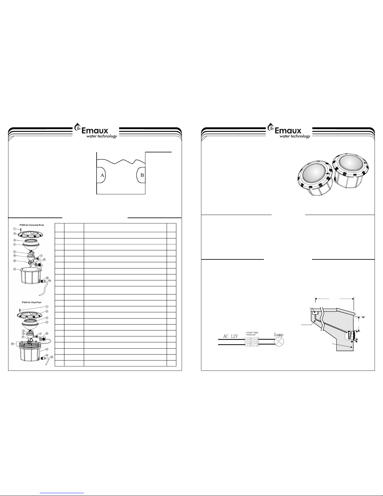
Figure 0.
Figure 5.
UL-P300 / LED-P300 Series Underwater Light
DANGER !
RISK OF ELECTRICAL SHOCK OR ELECTROCUTION
1-4
EMLI16 022770
A) Preparatory steps which must be completed by the electrician before light is installed, see Figure 1.
INSTALLATION
Figure 1.
120cm Min.
Water level
6.6CM
25CM
Rigid conduit
To power source;
feed paraffin
Concrete must be cut back
around niche to allow for
a compact plaster seal
45cm Min. from water
line to top of lens
This underwater light fixture must be installed by a licensed or certified electrician or a qualified serviceman
in accordance to the requirements of your government standard or local authorities. Improper installation
will create electric hazards which could result in serious injury, death as well as damage to the property.
Before servicing the light, disconnect the power supply from the circuit breaker. Failure to do so could result
in serious injury, death and or damage to the property.
1) Ensure that the electrical system and its wiring for the
pool conform to the requirements of your govenment or
your local authorities. The installation of the Underwater
Light should only be performed by a licensed
electrician.
a) The junction box, or the low voltage transformer for 12
volt Underwater Light model is to be located at least
120CM from the edge of the pool, see Figure 1.
b) The junction boxes shall not be installed in zones 0,1 and
2,where permitted for SELV circuits.
c) Terminal blocks must meet the IEC60988-2-1 standard
having the rated connecting capacity of 4,0mm2 use
of screw-type terminal at least 25A rated current
,mounted on junction boxes inside. See Figure 0
d) The light fixture and all metal parts that are within 240CM
of the pool must be properly protected with non-ductile
materials and that the connections must be waterproof.
User Manual
PLEASE READ THE FOLLOWING CAREFULLY AND
KEEP THIS USER MANUAL SAVE FOR FUTURE REFERENCE
4-4
One remote control can be max control 12pieces
Side control button
N = On
F = Off
Control Distance
Underwater 250mm, Max control distance 20m
Underwater 500mm, Max control distance 8m
Working in air, Max control distance 50m
Control Angle
Control Angle < 60°
In swimming pool
A position control A lamp
B position control B lamp
Authorized use in all EU countries, no restriction. Conform to the directive R&TTE 1999/5/CE
REPLACEMENT PARTS
Key
No.
Par t No.
Des cript ion
Qty
1
030 11323
M5X 40 Scre w for Fac e Plate f or Viny l Pool
1
1
030 11325
M5X 25 Scre w for Fac e Plate f or Conc rete Po ol
1
2
010 51066
Fac e Plate ( Blank )
1
2
010 51067
Fac e Plate ( Emaux )
1
3
020 21011
Gas ket for B ulb
1
4
040 11004
PAR 56 Ligh t Bulb (Y ellow L ight) ( Stand ard Bul b)
1
4
040 11043
Par 56 252 LE D Bulbs ( White -Colo ur)
1
4
040 11044
Par 56 252 LE D Bulbs ( Blue Co lour)
1
4
040 11045
Par 56 252 LE D Bulb (W ith Rem ote Con trol)
1
4
040 11056
Par 56 (252 L ED Bulb s)12V /16W (A utoma tic Col our
Cha nge)
1
4
040 11047
Par 56 144 LE D Bulbs ( White C olour )
1
4
040 11048
Par 56 144 LE D Bulbs ( Blue Co lour)
1
4
040 11049
Par 56 144 LE D Bulbs ( Autom atic Co lour Ch ange)
1
5
020 21001
Wat erpro of O-Ri ng for bu lb
1
6
012 71001
Wat erpro of Cove r
1
7
890 40301
Wat erpro of O-Ri ng with T ooth He ad for Ca ble
1
8
890 40312
Wat er Join t Fitti ngs for C able
1
9
030 14002
Spr ing
1
10
890 40304
P30 0 Light s Vinyl p ool fit ting
1
11
011 71107
P30 0 Light s Niche
112011 71106
Joi nt for Wi re & Pipe
1
13
040 13072
Cab le 2.5M
1
3-42-4
C) Winterizing: Light should be left in place for winterization.
B) Perform the following steps after the electrical system requirements are met.
1 Locate position on a vertical wall where light is to be
installed. The top of the light lens must be 45CM
below normal water level, see Figure 1.
2) Connect conduit to midst of Mounting Spacer (left
of Bracket),see Figure 3.
3) If pool surface is to be plastered, you must allow
proper concrete cutback for plaster thickness. Finish
concrete surface must be flush with Mounting
Spacer. CAUTION: Finish area surrounding Mounting
Spacer MUST be flat and flush with the face of
Mounting Spacer, this ensures a snug fit between
light and wall, see Figure 2.
4) After pool surface is finished, trim the Conduit.
5) Wrap a length of the cord up to a maximum of long
on the back of the light assembly. This extra cord
allows you to bring the light out of the pool for
revamping and servicing.
6) Connect cord electrical wires at Junction box,
through Conduit, be careful not to pull the 75mm-
80mm of slack cord at the light through the conduit
when connecting the wires.
7) Connect all wires to the corresponding circuit wires
in the junction box and feed paraffin.
8) Secure the junction box cover in place.
9) Before operating the light for more than 10 seconds
fill pool until the Underwater Light is completely
submerged in water. To check for proper operation
turn on main switch or circuit breaker as well as the
switch that operates the Underwater Light itself.
10) Rotating Locking System ensures light is secured to
bracket, see Figure 2.
)
Figure 2.
Figure 3.
Plastics
WARNING
!
!
Never operate this Underwater Light for more than 10 seconds unless it is totally submerged in
water. Without total submersion, the light assembly will get extremely hot, which may result in serious injury
to pool users, installers, or bystanders, or in damage to property.
Be sure power is off before installing or removing lamp. Allow lamp to cool before relamping. This
light fixture uses a Halogen Quartz lamp. Do Not touch lamp with bare hand, this may severely reduce its
life. Use the plastic furnished with the replacement lamp to eliminate finger prints from getting on lamp.
Concrete
LED PAR56 POOL LAMP SINGLE COLOR, RGB (COLOR CHANGING) BY SWITCH CONTROL & RGB (COLOR
CHANGING) WITH REMOTE CONTROL
Please read instructions before installation and keep for future reference.
PAR56LED 144LEDS WHITE, WARM WHITE, RED, BLUE, GREEN
PAR56LED 144LEDS RGB (COLOR CHANGING)
PAR56LED 252LEDS RGB (COLOR CHANGING)
PAR56LED 252LEDS WHITE, WARM WHITE, RED, BLUE, GREEN
PAR56LED 252LEDS RGB (COLOR CHANGING) SWITCH CONTROL/REMOTE CONTROL
Transformer: Required
Output voltage: 12V AC 50-60HZ
This PAR56 LED lamp is compatible with most immersed fixture for pool with PAR56 300W type. Though,
please consult your regular retailer before buying and installing this PAR56 LED lamp.
Switch off the power, remove the current PAR56 lamp out and replace the PAR56 LED lamp, following
the instructions on user's guide, then seal the fixture with a new silicon rubber ring, otherwise may cause
gap exists between lamp and fixture and burn the new lamp.
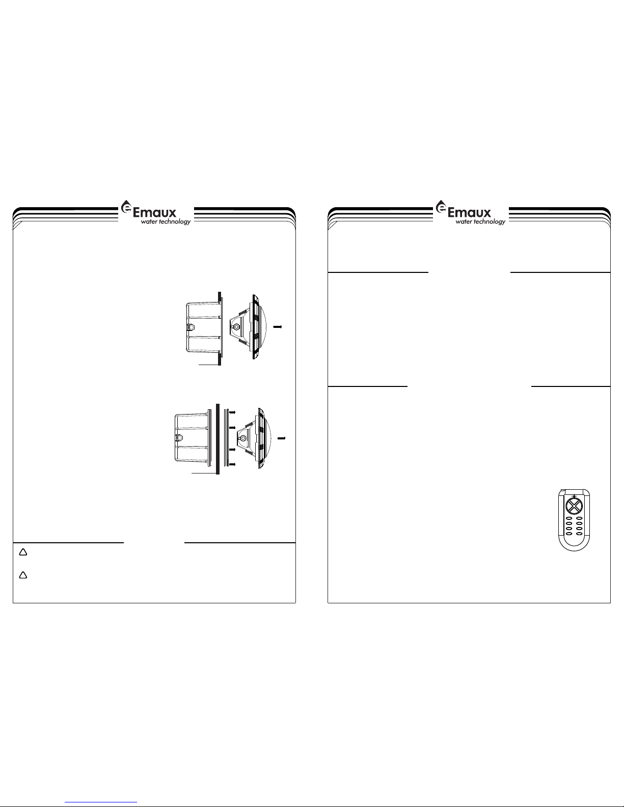
For remote controller:
Hold at least one second when press the button:
Button 1: turns on the lamp, three basic colors Red, Green and Blue all light
Buttons 2 to 11: various color changing program
Button 12: turns off the lamp
For better synchronization effect, please keep at least 5 second when turn on/off the PAR56 LED lamp,
then switch off/on again.
Figure 4.
SPECIFICATIONS
OPERATION PROCEDURE
PAR56 12 Programs
01) RGB (Red, Green and Blue LEDs light)
02) B (only Blue LEDs light)
03) R (only Red LEDs light)
04) G (only Green LEDs light)
05) RGB flashing every 4 sec (change color every 4 sec on the frequency of Red,
Green and Blue)
06) RGB flashing every 8 sec (change color every 8 sec on the frequency of Red,
Green and Blue)
07) RG/BG/BR flashing every 4 sec (change color every 4 sec on the frequency of
RG, BG and BR)
08) RG/BG/BR flashing every 8 sec (change color every 8 sec on the frequency of
RG, BG and BR)
09) RG/BG/BR flashing every 16 sec (change color every 16 sec on the frequency of
RG, BG and BR)
10) RG/BG/BR flashing every 0.5 sec (change color every 0.5 sec on the frequency of
RG, BG and BR)
11) RGB flashing every 0.5 sec (change color every 0.5 sec on the frequency of Red,
Green and Blue)
12) Off
e The mounting bracket must be properly installed so that the top edge of the Underwater Light lens is at
least 45CM below the surface of the water in the pool, see Figure 1.
2) Consult the local Government Building Department to be certain that the pool's electrical system meets
all applicable requirements.
)
 Loading...