

emaux FSU-4TP, FSU-4P, FSU-8P, FSU-8TP, FSU-6TP Installation & Operating Instruction
...
1
INSTALLATION
* Install filtration system including pump,filter tank and multiport valve.
* The filter system should be installed as close as possibie to the swimming pool and preferably at a level
of 0.50 metres below the surface of the water in the swimming pool. Make sure there is drainage available
at the place where the filter is to be installed.
* PUMP
1.Only qualified,licensed personnel should install pump and wiring.
2.Electrical Contractors Please Note:All 110 volt 60Hz pump must be wired to the main power supply
trough an approved and correctly rated contractor.
3.Allow for gate valve in suction piping.
4.Pump suction and discharge connections have moulded in
beyond these stops.
thread stops,do not try to screw pipe in
* FILTER TANK and MULTIPORT VALVE
1.Loading the sand media.Filter sand media is loaded through the top opening of the filter.
a.Loosen the plastic clamps from tank neck.
b.Cap internal pipe with plastic cap to prevent sand from entering it.
c.We recommend filling tank approximately 1/2 way with water to provide a cushion effect when the filter
sand is poured in. This helps protect the under-drain laterals from excessive shock.
d.Carefully pour in correct amount and grade of filter sand.Be sure center pipe remains centered in opening.
Sand surface should be leveled and should come to about the middle of the filter tank.Remove plastic cap
from internal pipe.
2.Assemble filter control valve to filter tank.
a.Insert filter control valve(with O'ring in place)into the tank neck,taking care that the center pipe slips
into the hole in the bottom of the valve.
b.Place two plastic clamps around valve flange and tank neck and tighten just enough so that the valve may
Be rotated on tank for final positioning.
c.Carefully screw pressure gauge(with O'ring in place)into tapped hole in valve body.Do not over-tighten.
d.Connect pump to control valve opening marked PUMP with hose.After connections are made,tighten
clamps with screwdrive,tapping around clamp with screwdrive handle to help seat valve flange clamp.
3.Make return to pool pipe connection to control valve opening marked RETURN and complete other
necessary plumbing connections,suction lines to pump,waste,etc.
4.To prevent water leakage,be sure all pipe connections are tight.
FILTER & PUMP COMBO
Installation & Operating
Instruction
EMFS14122972
4
By-passes filter for circulating water to pool
Used after backwash to flush dirt from valve
Cleaning Filter by reversing the flow
By-passes filter, used for vacuuming to waste or lowering water level
CLOSED Shuts off all flow to filter or pool
RECIRCULATE
WASTE
RINSE
BACKWASH
FILTER
Valve Position
Normal Filtration and Vacuuming
Function
THIS FILTER OPERATES UNDER HIGH PRESSURE. WHEN ANY PART OF THE CIRCULATING
SYSTEM (e.g., CLAMP, PUMP, FILTER, VALVES, ETC.) IS SERVICED, AIR CAN ENTER THE
SYSTEM AND BECOME PRESSURIZED . PRESSURIZED AIR CAN CAUSE THE LID OR VALVE TO
BE BLOWN OFF WHICH CAN RESULT IN SEVERE INJURY, DEATH, OR PROPERTY DAMAGE
TURN PUMP OFF BEFORE CHANGING VALVE POSITION.
WARNING
!
!
TO PREVENT DAMAGE TO THE PUMP AND FOR PROPER OPERATION OF THE SYSTEM,
CLEAN PUMP STRAINER AND SKIMMER BASKETS REGULARLY.
!
DO NOT UNSCREW SCREWS OF FLANGE CLAMP WHILE PUMP IS RUNNING.
!
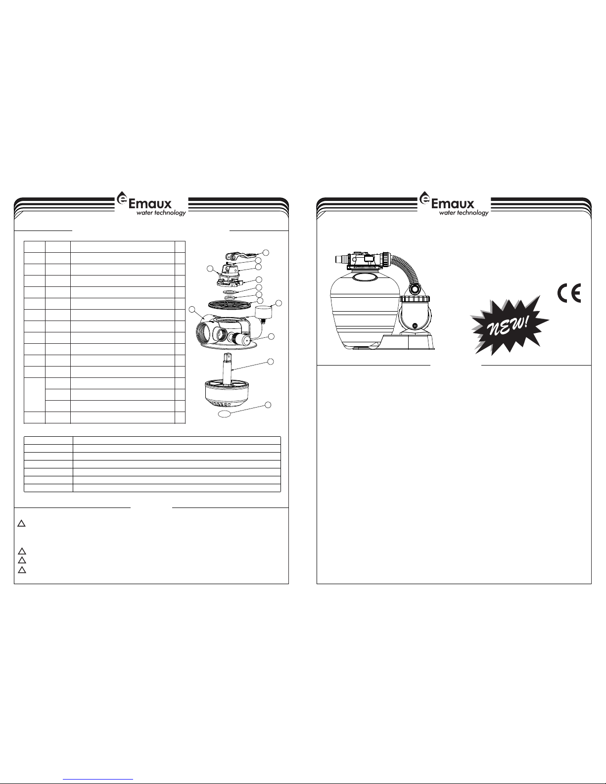
EM-VALVE FOR "ULTRA" REPLACEMENT PARTS
FSU-4TP FSU-4P FSU-6TP FSU-6P FSU-8TP FSU-8P
1
2
3
4
5
6
7
8
9
10
11
12
1
3
Key No.
Part No.
Product Description
Qty
1
01013130
Handle for 1.5"4-way Valve
1203018160
Pin for handle
1301013131
Fixation for 1.5"4-way Valve Handle
1
4
03011003
¢4*12 Self-drilling screw
3
5
01013132
Pressing Ring
1601181060
Washer for 1.5"4-way Valve Handle
1702011095
O-Ring for Rotor
2
8
02311010
Spider Gasket
1
9
06021014
Plastic pressure gauge With O-Ring (28Psi)
1
10
01013134
1.5"4-way Valve Body
1
11
89280104
Sight Glass with O-Ring
11201013137
1.5"4-way Valve Rotor Connector
1
01013133
Rotor for 1.5"4-way Valve
1
01013135
Diffuserfor 1.5"4-way Valve
11302011184
O-Ring for Diffuser
1
2
REPLACEMENT PARTS OF FILTER
1. Be sure correct amount of filter media sand is in tank and that all connections have been made and are secure.
2. Depress control valve handle and rotate to BACKWASH position. (To prevent damage to control valve seal,
3. Prime and start pump. Never tun pump dry! Running pump dry may damage seals,causing leakage and flooding!
Fill pump with water before starting motor. (be sure all suction and return lines are open), allowing the filter tank
to fill with water. Once water is flowing out of the waste line, run the pump for at least 1 minute. The initial
back-washing of the filter is recommended to remove any impurities or fine sand particles in the sand media.
4. Turn pump off and set valve to RINSE position. Start pump and operate until water in sight glass is clear, about
normal filter mode, filtering dirt particles from the pool water.
5. Adjust pool suction and return valves to achieve desired flow. Check system and filter for water leaks and tighten
6. Note the initial pressure gauge reading when the filter is clean. (It will vary from pool to pool depending upon the
initial "clean" pressure you noted, it is time to backwash the filter (see BACKWASH under filter and control
NOTE: During initial clean-up of the pool water it may be necessary to backwash frequently due to the unusually
INSTALL/START-UP OF FILTRATION
always depress handle before turning.)
1/2 to 1 minute. Turn pump off and set valve to FILTER position and restart pump.The filter is now operating in the
connections, bolts, nuts, as required.
pump and general piping system.) As the filter removes dirt and impurities from the pool water, the accumulation in the
filter will cause the pressure to rise and flow to diminish. When the pressure gauge reading is 1.5 bar, higher than the
heavy initial dirt load in the water.
valve functions).
AMU PUMP REPLACEMENT PARTS
Release all air from filter and piping system.
In a flooded suction system (water source higher than pump), pump will prime itself when suction and
discharge valves are opened.
If pump is not in a flooded suction system, unscrew and remove trap cover; fill trap and pump with water.
Clean and inspect Ring; re-install on trap cover.
Replace trap cover on trap; turn clockwise to tighten cover.
NOTICE: Tighten trap cover by hand only .Pump should prime now. Priming time will depend on vertical
length of suction lift and horizontal length of suction piping.
PRIMING PUMP
26
25
23
22
20
21
5
27
19
18
17
16
15
14
13
12
11
10
9
8
7
6
4
3
2
1
24
28
WARNINGS:
I
IIf the su pply cor d is damaged, it m ust be replace d by the manufac turer, its ser vice ag ent or sim ilarly
quali fied per sons in order to a void a hazard;
IThis ap plianc e is not intende d for use by perso ns (includin g children) wi th reduced phy sical, senso ry or mental
capab ilitie s, or lack of expe rience and kno wledge, unle ss they have bee n given superv ision or instr uction
conce rning us e of the applian ce by a person res ponsible for t heir safety; c hildren shou ld be supervis ed to
ensur e that the y do not play with t he appliance ;
IThe max imum tot al head is 1 metre ;
IPollu tion of th e liquid could o ccur due to leak age of lub ricants;
IThe pum p must not b e used when peop le are in t he water ;
IThe pum p must be su pplied throu gh a residual cu rrent device (RCD) h aving a ra ted resi dual operati ng
curre nt not exc eeding 30 mA.
EMAUX p umps mus t be wired to the ma in supply thro ugh an ap proved a nd licen sed electric ian.
!
3
15
3
2
14
11
6
2
13
16
17
12
11
1
10
9
8
5
7
6
5
4
2
1
Item N o.
Part N o.
Desc ripti on Engl ish
Qty
1
0101 3051
32mm & 3 8mm Ada ptor
3
2
0202 0013
O-R ing
4
3
8828 1105
4 Way Va lve
1
4
0101 3047
Hose a dapto r
1
5
0201 1026
Slee ve for Ho se
2
6
0101 3046
Nut fo r Hose
270137 0011
Hose
1
8
0101 3049
Hose a dapto r with nu t
1
9
0201 1104
O-R ing
1
10
8802 8519
AMU012TP AQUA-MINI Pump(with timer & pre-filter)
1
8802 7919
AMU012P AQUA-MINI Pump(with pre-filter)
1
8802 8520
AMU016TP AQUA-MINI Pump(with timer & pre-filter)
1
8802 7920
AMU016P AQUA-MINI Pump(with pre-filter)
1
8802 8501
AMU020TP AQUA-MINI Pump(with timer & pre-filter)
1
8802 7901
AMU020P AQUA-MINI Pump(with pre-filter)
1
11
8903 3601
Pump A ssemb ly Scre w
1
12
0111 1105
Comb o Base
1
13
0602 1014
Plas tic Pre ssure G auge Wi th O-R ing (28 psi)
1
14
8903 3602
Clam p Lock wi th Scre ws & Nut
1
15
0201 0045
O-R ing
1160133 1061
13" Fi lter Ta nk
1
17
8903 3603
Late ral Ass embly w ith Cen ter Pip e
1
Item N o.
Part N o.
Desc ripti on Engl ish
Qty
Item N o.
Part N o.
Desc ripti on Engl ish
Qty
1
0102 1067
Nut fo r lid
1140102 1069
Flan ge
128928 0105
1.5 "uni on (opt ional )
2150102 1068
Nut fo r body
1
0101 3015
1.5 "Con nector ( for i nput)
1160201 1156
Moto r Sling er
1
0101 3051
32- 38 Unio n (opt ional )
2170301 1067
Scre w for fla nge
4
3
0201 1104
O-R ing for 1 .5" Uni on
2
18
0402 1204
Moto r(AM U012T P/AMU 012P) (1 10V/ 60HZ)
1
0202 0013
O-R ing for 3 2-38 Un ion
2
0402 1204
Moto r(AM U016T P/AMU 016P) (1 10V/ 60HZ)
1
4
0104 1045
Tran spare nt Lid
1
0402 1205
Moto r(AM U020T P/AMU 020P) (1 10V/ 60HZ)
1
5
0202 0049
O-R ing for l id
1190132 1019
Fan Co ver
1
6
0111 1104
Bask et120
0401 6043
Capacitor for AMU012TP/AMU012P & AMU016TP/AMU016P (110V/60HZ)
1
7
0102 1070
AMU pu mp body
1
8
0202 0014
O-R ing
1210202 0048
Cove r Sling er
1
9
0111 1017
Drai n Plug
1220301 1007
Scre w for cab le Box
4
10
0111 1103
Diff user
1230132 1018
Cabl e Box
1
11
0131 1051
Impeller(AMU012TP/AMU012P)(110V/60HZ)
1240202 0012
Slin ger for c able Bo x
1
0131 1045
Impeller(AMU016TP/AMU016P)(110V/60HZ)
1250401 5041
PCB ( for AMU 012TP A MU016 TP AMU0 20TP)
1
0131 1046
Impeller(AMU020TP/AMU020P)(110V/60HZ)
1260301 1100
Scre w
4
12
0401 5002
1/2″M echan ical se al
1270111 1102
Base
1
13
0202 0011
O-R ing for f lange
1280301 1006
Scre w for bas e
1
 Loading...