

emaux FSP350-6W, FSP500-6W, FSP400-6W, FSP450-6W, FSP650-6W Installation & Operating Instruction
1
4
INSTALLATION
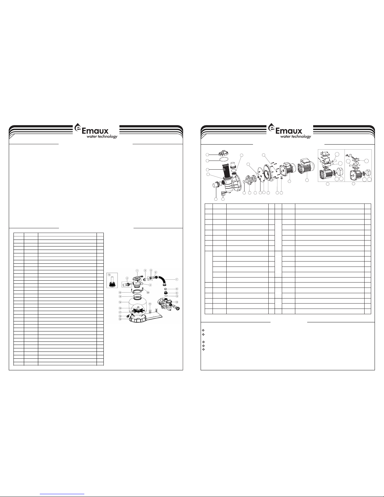
FILTER & PUMP COMBO
Installation & Operating Instruction
FSP350-6W / FSP400-6W / FSP450-6W / FSP500-6W / FSP650-6W
WARNING
VALVE REPLACEMENT PARTS
17
18
19
20
21
13
14
15
16
6
12
1
2
3
4
5
7
8
9
10
11
17
18
19
22
21
23
24
25
26
Item
Part N o.
Desc ripti on
Qty10101 3003
Hand le (Big )
120301 8008
Pin fo r Handl e
130118 1001
Wash er for Ha ndle
1
4
8928 0107
M6×3 0 Screw w ith Nut f or Stan dard Li d
6
5
0101 3004
1.5" T op Moun t Valve S tanda rd Lid (B lack)
160201 1002
O-Ri ng for 1. 5" Valv e Lid
1
7
0118 1002
Wash er for Sp ring
1
8
0301 4001
Spri ng for 1. 5" Top Mo unt Val ve
190201 1022
O-Ri ng for 1. 5" Valv e Rotor
2
10
0102 1001
1.5" V alve Ro tor
1
11
0231 1002
Spid er Gask et
1120101 3007
1.5" T op Moun t Valve B ottom B ody Cla mp (bla ck)
1
13
0101 3011
1.5" D iffus er
1
14
0201 1001
O-Ri ng for Di ffuse r
1150101 3012
1.5" T op Moun t Valve O ver Dra in Diff user
1160201 1134
O-Ri ng117
0202 0013
O-Ri ng for 1. 5" Conn ector
3180101 3015
1.5" C onnec tor (bl ack)
3190201 1003
O-Ri ng for 1. 5" Unio n
3
20
0117 1153
1.5" U nion (A /E)
2
21
0101 3017
1.5" U nion Nu t (blac k)
3220104 1002
1.5" U nion Wi th Sigh t Glass ( short )
1
23
0117 2026
1.5" U nion Wi th Sigh t Glass H older
1
24
0111 1048
Conn ector f or pres sure ga uge/s toppe r
1
0201 1139
O-ri ng
1
25
8902 1703
Drai n Plug wi th O-ri ng
1
26
0602 1013
Plas tic Pre ssure G auge Wi th O-Ri ng (40p si)
1
By-passes filter for circulating water to pool
Used after backwash to flush dirt from valve
Cleaning Filter by reversing the flow
By-passes filter, used for vacuuming to waste or lowering water level
CLOSED Shuts off all flow to filter or pool
RECIRCULATE
WASTE
RINSE
BACKWASH
FILTER
Valve Position
Normal Filtration and Vacuuming
Function
EMFS16 03095 2
* Install filtration system including pump,filter tank and multiport valve.
* The filter system should be installed as close as possibie to the swimming pool and preferably at a level
of 0.50 metres below the surface of the water in the swimming pool. Make sure there is drainage
available at the place where the filter is to be installed.
* PUMP
1) Only qualified,licensed personnel should install pump and wiring.
2) Electrical Contractors Please Note:All 220 volt 50Hz pump must be wired to the main power supply
trough an approved and correctly rated contractor.
3) Allow for gate valve in suction piping.
4) Pump suction and discharge connections have moulded in thread stops,do not try to screw pipe in
beyond these stops.
* FILTER TANK and MULTIPORT VALVE
1) Loading the sand media.Filter sand media is loaded through the top opening of the filter.
a) Loosen the plastic clamps from tank neck.
b) Cap internal pipe with plastic cap to prevent sand from entering it.
c) We recommend filling tank approximately 1/2 way with water to provide a cushion effect when the
filter sand is poured in. This helps protect the under-drain laterals from excessive shock.
d) Carefully pour in correct amount and grade of filter sand.Be sure center pipe remains centered in
opening. Sand surface should be leveled and should come to about the middle of the filter
tank.Remove plastic cap from internal pipe.
2) Assemble filter control valve to filter tank.
a) Insert filter control valve(with O'ring in place)into the tank neck,taking care that the center pipe slips
into the hole in the bottom of the valve.
b) Place two plastic clamps around valve flange and tank neck and tighten just enough so that the
valve mayBe rotated on tank for final positioning.
c) Carefully screw pressure gauge(with O'ring in place)into tapped hole in valve body.Do not over-
tighten.
d)Connect pump to control valve opening marked PUMP with hose.After connections are made,
tighten clamps with screwdrive,tapping around clamp with screwdrive handle to help seat valve
flange clamp.
3) Make return to pool pipe connection to control valve opening marked RETURN and complete other
necessary plumbing connections,suction lines to pump,waste,etc.
4) To prevent water leakage,be sure all pipe connections are tight.
THIS FILTER OPERATES UNDER HIGH PRESSURE. WHEN ANY PART OF THE CIRCULATING SYSTEM
(e.g., CLAMP, PUMP, FILTER, VALVES, ETC.) IS SERVICED, AIR CAN ENTER THE SYSTEM AND BECOME
PRESSURIZED . PRESSURIZED AIR CAN CAUSE THE LID OR VALVE TO BE BLOWN OFF WHICH CAN
RESULT IN SEVERE INJURY, DEATH, OR PROPERTY DAMAGE.
TURN PUMP OFF BEFORE CHANGING VALVE POSITION.
TO PREVENT DAMAGE TO THE PUMP AND FOR PROPER OPERATION OF THE SYSTEM.CLEAN PUMP
STRAINER AND SKIMMER BASKETS REGULARLY.
DO NOT UNSCREW SCREWS OF FLANGE CLAMP WHILE PUMP IS RUNNING.
!
!
!
!
SS PUMP REPLACEMENT PARTS
PRIMING PUMP
INSTALL/START-UP OF FILTRATION
REPLACEMENT PARTS OF FILTER
1
5
7
8
9
10
11
12
13
15
14
16
2
3
4
6
17
17
17
17
23
21
21
22
18
19
18
20
22
3
2
Item
Part N o.
Desc ripti on
Qty
Item
Part N o.
Desc ripti on
Qty10120 1031
Tran spare nt Lid
1
15
0201 1153
Moto r Sling er for SS 050- SS12 0
1
2
0201 1074
O-R ing for l id
1
16
8902 2404
Moto r suppo rt
1
3
0111 2051
Bask et
1
17
8902 2109
Moto r SS020 (220 V/50 Hz)
1
4
0102 1064
SS Pum p Pre- filt er
1
8902 2110
Moto r SS033 (220 V/50 Hz)
1
5
8928 0105
1.5 "uni on
2
8902 2105
Moto r SS050 (220 V/50 Hz)
168902 2402
Drai n Plug Wi th O'r ing
1
8902 2106
Moto r SS075 (220 V/50 Hz)
1
7
0201 1004
O-R ing for d iffus er
1
8902 2107
Moto r SS100 (220 V/50 Hz)
1
8
0111 1014
Diff user
1
8902 2108
Moto r SS120 (220 V/50 Hz)
1
9
0131 1015
Impe ller SS 020( 220V /50H z)
1
18
0401 6009
Capa citor f or SS05 0 Pump( 220 V/50 Hz/6 0Hz)
1
0131 1016
Impe ller SS 033( 220V /50H z)
1
0401 6010
Capa citor f or SS07 5 Pump( 220 V/50 Hz/6 0Hz)
1
0131 1017
Impe ller SS 050( 220V /50H z)
1
0401 6012
Capa citor f or SS10 0、SS120 P ump( 220V /50H z/60 Hz)
1
0131 1018
Impe ller SS 075( 220V /50H z)
1
0401 6030
Capa citor f or SS02 0 Pump( 220 V/50 Hz/6 0Hz)
1
0131 1019
Impe ller SS 100( 220V /50H z)
1
0401 6031
Capa citor f or SS03 3 Pump( 220 V/50 Hz/6 0Hz)
1
0131 1014
Impe ller SS 120( 220V /50H z)
1
19
8902 2112
Cabl e Box for S S050- SS1 20 Pump
1
10
8902 2403
M8* 16 Scr ew with w asher
4
20
8902 2111
Cabl e Box for S S020- SS0 33 Pump
1
11
0401 5033
1/2 "Mec hanic al seal
1
21
0103 1027
Cool ing fan f or SS05 0-SS 120 Pum p
1120201 1090
O-R ing for F lange
1
0103 1026
Cool ing fan f or SS02 0-SS 033 Pum p
1
13
0102 1065
SS Pum p Flang e
1
22
0103 1011
Fan Co ver for S S020- SS0 33 Pump
1
14
0301 1035
M6* 30 Scr ew
8
0103 1010
Fan Co ver for S S050- SS1 20 Pump
1
15
0201 1156
Moto r Sling er for SS 020- SS03 3
1
23
0201 1104
O-R ing
2
1 Be sure correct amount of filter media sand is in tank and that all connections have been made and are secure.
2 Depress control valve handle and rotate to BACKWASH position. (To prevent damage to control valve seal, always depress
handle before turning.)
3 Prime and start pump. Never tun pump dry! Running pump dry may damage seals,causing leakage and flooding! Fill pump
with water before starting motor. (be sure all suction and return lines are open), allowing the filter tank to fill with water. Once
water is flowing out of the waste line, run the pump for at least 1 minute. The initial back-washing of the filter is recommended to
remove any impurities or fine sand particles in the sand media.
4 Turn pump off and set valve to RINSE position. Start pump and operate until water in sight glass is clear, about 1/2 to 1 minute.
Turn pump off and set valve to FILTER position and restart pump.The filter is now operating in the normal filter mode, filtering dirt
particles from the pool water.
5 Adjust pool suction and return valves to achieve desired flow. Check system and filter for water leaks and tighten
connections, bolts, nuts, as required.
6 Note the initial pressure gauge reading when the filter is clean. (It will vary from pool to pool depending upon the pump and
general piping system.) As the filter removes dirt and impurities from the pool water, the accumulation in the filter will cause
the pressure to rise and flow to diminish. When the pressure gauge reading is 1.5 bar, higher than the initial "clean" pressure you
noted, it is time to backwash the filter (see BACKWASH under filter and control valve functions).
NOTE: During initial clean-up of the pool water it may be necessary to backwash frequently due to the unusually heavy initial dirt
load in the water.
)
)
)
)
)
)
Release all air from filter and piping system.
In a flooded suction system (water source higher than pump), pump will prime itself when suction and
discharge valves are opened.
If pump is not in a flooded suction system, unscrew and remove trap cover; fill trap and pump with water.
Clean and inspect Ring; re-install on trap cover.
Replace trap cover on trap; turn clockwise to tighten cover.
NOTICE: Tighten trap cover by hand only .Pump should prime now. Priming time will depend on vertical
length of suction lift and horizontal length of suction piping.
Key No .
Part N o.
Desc ripti on
Qty
1*
8828 0105
1.5" T op Moun t Valve ( Black / White C olour )
1
2*
8928 0101
1.5" U nion wi th Sigh t Glass ,O-Ri ng (Bla ck/ Whi te Colo ur)
1
3*
8928 0102
1.5" U nion Se t With O- Ring (B lack/ W hite Co lour)
1
4
0602 1001
Plas tic Pre ssure G auge wi th O-Ri ng (35p si)
1
4
0111 1048
Conn ector f or Pres sure Ga uge/ St opper
1
5
8903 0204
Hose A dapto r with O- Ring
1
6
0201 1026
Slee ve for Ho se
2
7
8903 1501
FSP3 50-6W P lasti c Hose wi th Nut
178903 1601
FSP4 00-6W P lasti c Hose wi th Nut
1
7
8903 1701
FSP4 50-6W P lasti c Hose wi th Nut
1
7
8903 1801
FSP5 00-6W P lasti c Hose wi th Nut
1
7
8903 1901
FSP6 50-6W P lasti c Hose wi th Nut
1
8
0101 3049
Hose A dapto r with Nu t
1
9
0201 1104
O-Ri ng for 1. 5" Unio n
1
10
8802 2401
FSF3 50-4W P ump (SS 020)
1
10
8802 2402
FSF4 00-6W P ump (SS 033)
1
10
8802 2403
FSP4 50-6W P ump (SS 050)
1
10
8802 2404
FSP5 00-6W P ump (SS 075)
1
10
8802 2405
FSP6 50-6W P ump (SS 100)
1
11
8903 2001
Pump A ssemb ly Scre w
2
12
0127 1010
Clam p Lock
2
13
0201 1134
O-Ri ng for Fi lter Ne ck
1
14
0133 1005
P350 F ilter T ank
1
14
0133 1006
P400 F ilter t ank
1
14
0133 1007
SP/P 450 Fil ter tan k
1
14
0133 1008
SP/P 500 Fil ter tan k
1
14
0133 1010
SP/P 650 Fil ter tan k
1
15
8901 1602
P350 L atera l Assem bly wit h Cente r Pipe
1
16
8901 1603
P400 L atera l Assem bly wit h Cente r Pipe
1
16
8901 1604
P450 L atera l Assem bly wit h Cente r Pipe
1
16
8901 1605
P500 L atera l Assem bly wit h Cente r Pipe
1
16
8901 1606
P650 L atera l Assem bly wit h Cente r Pipe
1
17
0117 2007
Late rals (1 15mm) f or P/V4 00-P/ V450
8
17
0117 2008
Late rals (1 26mm) f or P/V5 00-P/ V650
8
18
8901 1601
Wate r Drain S et
1
19
0111 1056
FSP/ F350- 4-6W Co mbo Bas e
1
19
0111 1053
FSP/ F400- 6W - FSP/ F650- 6W Comb o base
1
20
8901 0119
M6 x 50 Sc rews wi th Nut
2
 Loading...