

emaux FSF350-6W, FSF450-6W, FSF500-6W, FSF650-6W, FSF400-6W Installation & Operating Instruction
INSTALLATION
WARNING
By-passes filter for circulating water to pool
Used after backwash to flush dirt from valve
Cleaning Filter by reversing the flow
By-passes filter, used for vacuuming to waste or lowering water level
CLOSED Shuts off all flow to filter or pool
RECIRCULATE
WASTE
RINSE
BACKWASH
FILTER
Valve Position
Normal Filtration and Vacuuming
Function
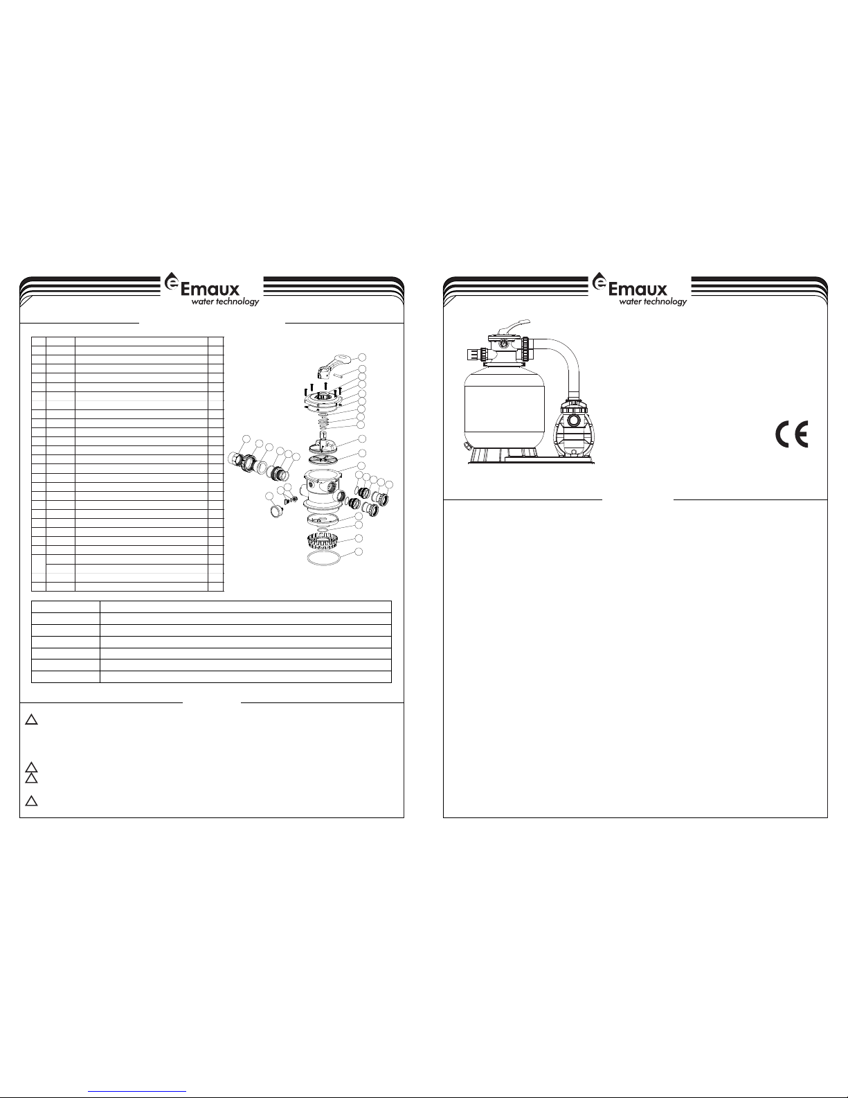
VALVE REPLACEMENT PARTS
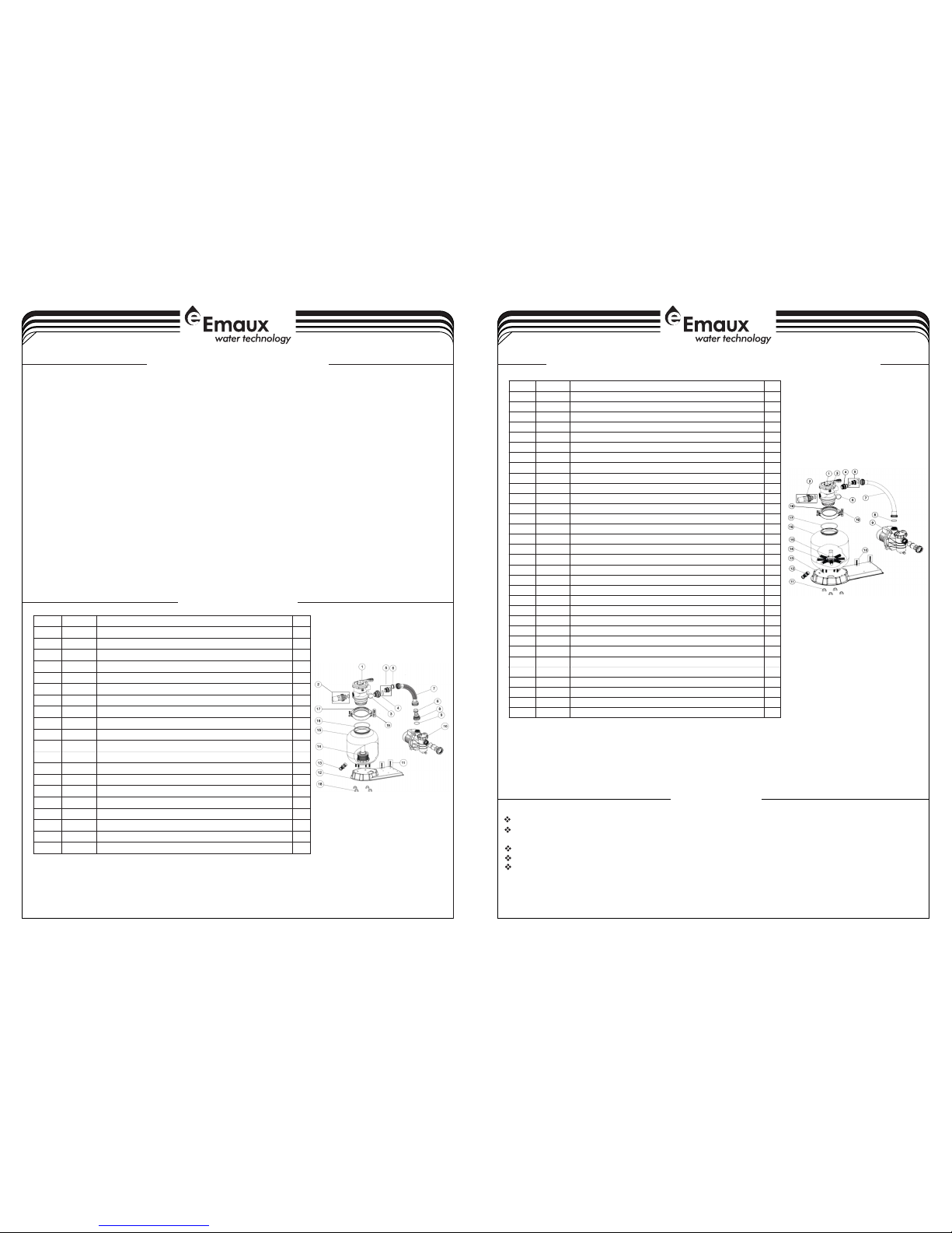
FILTER & PUMP COMBO
Installation & Operating Instruction
FSF350-6W / FSF400-6W / FSF450-6W
FSF500-6W / FSF650-6W
1-4
4-4
17
18
19
20
21
13
14
15
16
6
12
1
2
3
4
5
7
8
9
10
11
17
18
19
22
21
23
24
25
26
* Install filtration system including pump,filter tank and multiport valve.
* The filter system should be installed as close as possibie to the swimming pool and preferably at a
level of 0.50 metres below the surface of the water in the swimming pool. Make sure there is
drainage available at the place where the filter is to be installed.
* PUMP
1) Only qualified,licensed personnel should install pump and wiring.
2) Electrical Contractors Please Note:All 220 volt 50Hz pump must be wired to the main power supply
trough an approved and correctly rated contractor.
3) Allow for gate valve in suction piping.
4) Pump suction and discharge connections have moulded in thread stops,do not try to screw pipe in
beyond these stops.
* FILTER TANK and MULTIPORT VALVE
1) Loading the sand media.Filter sand media is loaded through the top opening of the filter.
a) Loosen the plastic clamps from tank neck.
b) Cap internal pipe with plastic cap to prevent sand from entering it.
c) We recommend filling tank approximately 1/2 way with water to provide a cushion effect when the
filter sand is poured in. This helps protect the under-drain laterals from excessive shock.
d) Carefully pour in correct amount and grade of filter sand.Be sure center pipe remains centered in
opening. Sand surface should be leveled and should come to about the middle of the filter
tank.Remove plastic cap from internal pipe.
2) Assemble filter control valve to filter tank.
a) Insert filter control valve(with O'ring in place)into the tank neck,taking care that the center pipe slips
into the hole in the bottom of the valve.
b) Place two plastic clamps around valve flange and tank neck and tighten just enough so that the valve
mayBe rotated on tank for final positioning.
c) Carefully screw pressure gauge(with O'ring in place)into tapped hole in valve body.Do not over-
tighten.
d) Connect pump to control valve opening marked PUMP with hose.After connections are
made,tighten clamps with screwdrive,tapping around clamp with screwdrive handle to help seat
valve flange clamp.
3) Make return to pool pipe connection to control valve opening marked RETURN and complete other
necessary plumbing connections,suction lines to pump,waste,etc.
4) To prevent water leakage,be sure all pipe connections are tight.
THIS FILTER OPERATES UNDER HIGH PRESSURE. WHEN ANY PART OF THE CIRCULATING SYSTEM
(e.g., CLAMP, PUMP, FILTER, VALVES, ETC.) IS SERVICED, AIR CAN ENTER THE SYSTEM AND
BECOME PRESSURIZED . PRESSURIZED AIR CAN CAUSE THE LID OR VALVE TO BE BLOWN OFF
WHICH CAN RESULT IN SEVERE INJURY, DEATH, OR PROPERTY DAMAGE.
TURN PUMP OFF BEFORE CHANGING VALVE POSITION.
TO PREVENT DAMAGE TO THE PUMP AND FOR PROPER OPERATION OF THE SYSTEM.CLEAN
PUMP STRAINER AND SKIMMER BASKETS REGULARLY.
DO NOT UNSCREW SCREWS OF FLANGE CLAMP WHILE PUMP IS RUNNING.
!
!
!
!
Item
Part N o.
Desc ripti on
Qty
1
0101 3003
Hand le(Bi g)
1
2
0301 8008
Pin fo r Handl e
1
3
0118 1001
Wash er for Ha ndle
148928 0107
M6×3 0 Screw w ith Nut f or Stan dard Li d
6
5
0101 3004
1.5" Top Mou nt Valv e Stand ard Lid ( Black )
1
6
0201 1002
O-Ri ng for 1. 5" Valv e Lid
1
7
0118 1002
Wash er for Sp ring
1
8
0301 4001
Spri ng for 1. 5" Top Mo unt Val ve
190201 1022
O-Ri ng for 1. 5" Valv e Rotor
2
10
0102 1001
1.5" V alve Ro tor
1
11
0231 1002
Spid er Gask et
1
12
0101 3007
1.5" Top Mou nt Valv e Botto m Body Cl amp(b lack)
1
13
0101 3011
1.5" D iffus er
1
14
0201 1001
O-Ri ng for Di ffuse r
1
15
0101 3012
1.5" Top Mou nt Valv e Over Dr ain Dif fuser
1
16
0201 1134
O-Ri ng
1
17
0202 0013
O-Ri ng for 1. 5"Con necto r
3
18
0101 3015
1.5" Conne ctor (b lack)
3
19
0201 1003
O-Ri ng for 1. 5"Uni on
3
20
0117 1153
1.5" Union ( A/E)
2210101 3017
1.5" Union N ut (bla ck)
3
22
0104 1002
1.5" Union W ith Sig ht Glas s (shor t)
1
23
0117 2026
1.5" Union W ith Sig ht Glas s Holde r
1
24
0111 1048
Conn ector f or pres sure ga uge/s toppe r
1
0201 1139
O-ri ng
1
25
8902 1703
Drai n Plug wi th O-ri ng
1
26
0601 1029
Oil Pr essur e Gauge W ith O-r ing (40 Psi)
1
EMFS16031401
Parts of FSF350-6W
INSTALL/START-UP OF FILTRATION
2-4
3-4
PRIMING PUMP
1 Be sure correct amount of filter media sand is in tank and that all connections have been made and are secure.
2 Depress control valve handle and rotate to BACKWASH position. (To prevent damage to control valve seal,
always depress handle before turning.)
3 Prime and start pump. Never tun pump dry! Running pump dry may damage seals,causing leakage and
flooding! Fill pump with water before starting motor. (be sure all suction and return lines are open), allowing the
filter tank to fill with water. Once water is flowing out of the waste line, run the pump for at least 1 minute. The initial
back-washing of the filter is recommended to remove any impurities or fine sand particles in the sand media.
4 Turn pump off and set valve to RINSE position. Start pump and operate until water in sight glass is clear, about 1/2 to
1 minute. Turn pump off and set valve to FILTER position and restart pump.The filter is now operating in the normal
filter mode, filtering dirt particles from the pool water.
5 Adjust pool suction and return valves to achieve desired flow. Check system and filter for water leaks and tighten
connections, bolts, nuts, as required.
6 Note the initial pressure gauge reading when the filter is clean. (It will vary from pool to pool depending upon the
pump and general piping system.) As the filter removes dirt and impurities from the pool water, the
accumulation in the filter will cause the pressure to rise and flow to diminish. When the pressure gauge reading is
1.5 bar, higher than the initial "clean" pressure you noted, it is time to backwash the filter (see BACKWASH under
filter and control valve functions).
NOTE: During initial clean-up of the pool water it may be necessary to backwash frequently due to the unusually
heavy initial dirt load in the water.
)
)
)
)
)
)
Release all air from filter and piping system.
In a flooded suction system (water source higher than pump), pump will prime itself when suction and
discharge valves are opened.
If pump is not in a flooded suction system, unscrew and remove trap cover; fill trap and pump with water.
Clean and inspect Ring; re-install on trap cover.
Replace trap cover on trap; turn clockwise to tighten cover.
NOTICE: Tighten trap cover by hand only .Pump should prime now. Priming time will depend on vertical
length of suction lift and horizontal length of suction piping.
Key N o.
Par t No.
Des cript ion
QTY
1*
882 80105
1.5 " Top Mou nt Valv e (Blac k/ Whit e colou r)
1
2*
892 80101
1.5" U nionw ith Sig ht Glas s and O-R ing (Bl ack/ Wh ite col our)
1
3
060 11029
Max imum 40 PSI Ind icati on, Sta inles s Steel C asing
1
3
011 11048
Con necto r for Pre ssure G auge/ Stopp er
1
4*
892 80102
1.5 " Union S et with O -Ring ( Black / White c olour )
1
5
890 30204
Hos e Adapt or with O -Ring
1
6
020 11026
Sle eve for H ose
2
7
890 32002
FSF 350-6 W Plast ic Hose w ith Nut
1
8
010 13049
Hos e Adapt or with N ut
1
9
020 11104
O-R ing for 1 .5" Uni on
1
10
880 22402
FSF 350-6 W Pump (S S033)
1
11
890 32001
Pum p Assem bly Scr ew
2
12
011 11056
FSP /F350 -4-6W C ombo Ba se
1
13
890 10107
Wat er Drai n Set
1
14
890 10106
V35 0 Later al Asse mbly wi th Cent er Pipe
1
15
890 10115
V35 0 Filte r tank
1
16
020 11134
O-R ing for F ilter N eck
1
17
012 71010
Cla mp Lock
2
18
011 81052
Fas tener f or Filt er base
4
19
890 10119
M6* 50 Scre ws With N ut
2
Parts of FSF400-6W / FSF450-6W / FSF500-6W / FSF-650-6W
Notes: 1* 88280105B is 1.5" Top Mount Valve in Black colour
1* 88280105W is 1.5" Top Mount Valve in White colour
2* 89280101B is 1.5" Union with Sight Glass and O-Ring in Black colour
2* 89280101W is 1.5" Union with Sight Glass and O-Ring in White colour
4* 89280102B is 1.5" Union Set with O-Ring in Black colour
4* 89280102W is 1.5" Union Set with O-Ring in White colour
Key No.
Par t No.
Des cript ion
QTY
1*
882 80105
1.5 " Top Mou nt Valv e (Blac k/ Whit e Colou r)
1
2*
892 80101
1.5" U nion wi th Sigh t Glass a nd O-Ri ng (Bla ck/ Whi te Colo ur)
1
3
011 11048
Con necto r for Pre ssure G auge/ Stopp er
1
4*
892 80102
1.5 " Union S et with O -Ring ( Black / White C olour )
15890 32102
1.5 " Bulkh aed Fit ting wi th O-Ri ng
1
6
060 11029
Max imum 40 PSI Ind icati on, Sta inles s Steel C asing
1
7
890 32103
FSF 400-6 W Plast ic Hose w ith Nut
1
7
890 32201
FSF 450-6 W Plast ic Hose w ith Nut
1
7
890 32301
FSF 500-6 W Plast ic Hose w ith Nut
1
7
890 32401
FSF 650-6 W Plast ic Hose w ith Nut
1
8
020 11104
O-R ing for 1 .5" Uni on
19880 22403
Pum p 0.50h p, 220V /50Hz , Singl e Phase
1
9
880 22404
Pum p 0.75h p, 220V /50Hz , Singl e Phase
1
9
880 21705
Pum p 1.00h p, 220V /50Hz , Singl e Phase
19880 21707
Pum p 1.50h p, 220V /50Hz , Singl e Phase
110890 32001
Pum p Assem bly Scr ew
2
11
011 81052
Fas tener f or Filt er Base
4
12
890 10107
Wat er Drai n Set
113011 11053
FSP /F400 -6W - FSP /F650 -6W Com bo Base
114011 72007
Lat erals (115m m)
814011 72008
Lat erals ( 126mm )
815890 10116
V40 0 Later al Asse mbly wi th Cent er Pipe
1
15
890 10105
V45 0 Later al Asse mbly wi th Cent er Pipe
115890 10104
V50 0 Later al Asse mbly wi th Cent er Pipe
1
15
890 10103
V65 0 Later al Asse mbly wi th Cent er Pipe
1
16
890 10113
V40 0 Filte r tank
1
16
890 10112
V45 0Filt er Tank
1
16
890 10111
V50 0 Filte r tank
1
16
890 10110
V65 0 Filte r tank
117020 11134
O-R ing for F ilter N eck
118012 71010
Cla mp Lock
219890 10119
M6* 50 Scre ws With N ut
2
Notes: 1* 88280105B is 1.5" Top Mount Valve in Black Colour
1* 88280105W is 1.5" Top Mount Valve in White Colour
2* 89280101B is 1.5" Union with Sight Glass and O-Ring in Black Colour
2* 89280101W is 1.5" Union with Sight Glass and O-Ring in White Colour
4* 88280102B is 1.5" Union Set wirh O-ring in Black Colour
4* 88280102W is 1.5" Union Set wirh O-ring in White Colour
 Loading...