

emaux E-Lumen-252, E-Lumen-441, E-Lumen-531 Operating Manual
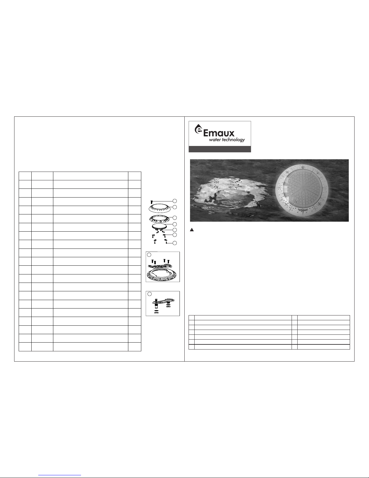
E-Lumen
UNDERWATER LIGHT
OPERATING MANUAL
Keep this manual for future reference
www.emauxgroup.com
REPLACEMENT PARTS
MAINTENANCE OF THE LIGHTS
1) Do not leave the lights “on” above water for longer than 1 minute.
2) Before switching on the lights, check whether the lights are fully submerged underwater and
the circuit boxes are running properly.
3) This unit does not need any kind of maintenance. If it is not working properly, please contact
EMAUX authorized dealer where you purchase the unit from.
4) Warranty will be voided if the Emaux Underwater Light was dismantled by unauthorized
personnel.
13
14
Mod e E: RGB Co lour Se quenc e: Red> Green >Blue
Mod e F: Four C olour S equen ce: Red >Gree n>Blu e>Pur ple
Aut o Colou r Chang e
1
3
5
7
9
11
2
4
6
8
10
12
Whi te
Gre en
Gre en+Bl ue
Red +Blue
Mod e B: Gree n+Gra dual Re d
Blu e
Red +Gree n
Mod e C: Blue +Grad ual Gre en
Mod e A: Blue + Gradu al Red
Mod e D: Blue +Grad ual Red
Rap id Auto C olour C hange
Only suitably qualified installers is allowed to carry out the installation of this product.
•
•
•
•
•
•
•
Avoid direct contact with electrical power.
Respect all regulations in effect for preventing accidents.
All units are required to be disconnected from the main electricity before any operation of maintenance.
Never handle with wet hands and feet.
Thi s unit is d esign f or use on ly when f ully su bmerg ed in wat er, con necti ng with a s afety t ransf ormer .
Never operate this Underwater Light for more than 1 minute unless it is totally submerged in water.
Be sure power is off before installing or removing LED plate. Allow LED plate to cool before replacing.
This product should be installed according to your local electrical installation ordinances and regulations.
Maximum Depth for Light installation at 1 meter.
o
Maximum Water Temperature Range for light operation 0 - 30 C
SPECIFICATION
A) Electrical Specification : 1) Voltage : AC12V 2) Frequency : 50/60Hz 3) Power : 20W/35W/50W
B) Colour change options(For RGB version only)
•
•
•
•
SAFETY WARNINGS
for type Z attachments
The external flexible cable or cord of this luminaire cannot be replaced;if the cord is damaged,the
luminaire shall be destroyed.
•
Mod el:E-Lu men-2 52 / E-Lu men-4 41 / E-Lu men-5 31
EMLI16 022764
4-4 4-1
Key N o.
Par t No.
Des cript ion
Qty
1
030 11321
M5* 20 Scre w (316# )
1
2
010 40205
Tra nspar ent Fac e Plate
13010 51256
Fac e Plate
1
4
890 45528
Ult raThi n LED Pan el 20W/ 12V for 2 52 LED (W arm whi te)
14890 45529
Ult raThi n LED Pan el 20W/ 12V for 2 52 LED (C ool whi te)
1
4
890 45530
Ult raThi n LED Pan el 20W/ 12V for 2 52 LED (R GB)
1
4
890 45531
Ult raThi n LED Pan el 20W/ 12V for 2 52 LED (S ingle b lue)
1
4
890 45522
Ult raThi n LED Pan el 35W/ 12V for 4 41 LED (W arm whi te)
1
4
890 45513
Ult raThi n LED Pan el 35W/ 12V for 4 41 LED (C ool whi te)
14890 45514
Ult raThi n LED Pan el 35W/ 12V for 4 41 LED (R GB)
1
4
890 45523
Ult raThi n LED Pan el 35W/ 12V for 4 41 LED (S ingle b lue)
1
4
890 45524
Ult raThi n LED Pan el 50W/ 12V for 5 31 LED (W arn whi te)
1
4
890 45526
Ult raThi n LED Pan el 50W/ 12V for 5 31 LED (C ool whi te)
1
4
890 45527
Ult raThi n LED Pan el 50W/ 12V for 5 31 LED (R GB)
1
4
890 45525
Ult raThi n LED Pan el 50W/ 12V for 5 31 LED (S ingle b lue)
1
5
010 50100
Kno t
46011 10028
Pre ssing F ittin g
1
7
030 11307
M4* 12 Scre w
4
8
890 40203
Fit ting fo r Concr ete Poo l
19890 45517
Fit ting fo r Vinly P ool
1
9
8
Con crete P ool
Vin yl Pool
7
6
5
4
3
2
1

C) Fiberglass Pools / Vinyl Pools Installation
1) Refer to section"Preparing to Install".
2) Make 2 holes on the pool wall (Figure 8).
3) Place the o-rings between the Mounting Plate and the pool wall and tighten it with the Nut on
the other side of the pool wall (Figure 9).
4) Put the cable sequentially through the sealing Nut, the sealing O-ring and the cable hole on
the mounting plate; then tighten the Nut (Figure10).
5) Wrap extra cables behind the light to make sure it could be taken to the pool surface for future
maintenance. Then, hang the light onto the Mounting Plate and tighten the screws (Figure 11).
B) Pool Installation
1) Embed the Wall Mount into the concrete wall, making sure that it is parallel to the side of the
pool.(Figure 4).
2) Place the Mounting Plate on the concrete wall and tighten it with 4 screws. The Conduit must
be next to the Mounting Plate (Figure 5).
3) Note that the light must only be installed on a flat or concave surface.
4) Wrap extra cables behind the light to make sure it could be taken to the pool surface for future
maintenance (Figure 6).
5) Hang the light onto the Mounting Plate and tighten the screws (Figure 7).
6) The wire connections inside the terminal box must be sealed by leak-proof tapes to prevent
water from leaking into the terminal box through the cables.
Figure 4
Figure 6
Figure 7
Figure 5
Figure 9
Figure 10
Figure 8
Figure 11
4-3
4-2
INSTALLATION NOTES
1) You should follow the procedures closely when installing the
light.
2) It is recommended to install a light every 20m , the approximate
exposure area of each unit.
3) The lights should be installed in the direction that they will not
shine directly into the house.
4) For training or competition pools, the lights must be installed on
the sides in order to prevent swimmers from seeing any glare.
5) Nothing should be placed on the poolside directly above the
lights for ease of future maintenance.
6) If the wires are connected inside the lights, you must seal the
connections with leak-proof tapes or products with the same
function.
7) The cables connecting the lights and the transformers must be
2
at least 6mm and the distance between them must not
exceed 30m (Figure 2); otherwise the lights will not function
properly.
)
2
8 Terminal blocks must meet the IEC60988-2-1 standard having
the rated connecting capacity of 4,0mm2 use of screw-type
terminal at least 25A rated current ,mounted on junction boxes
inside. See Figure2-1
Figure 2
INSATALLATION OF THE UNDERWATER LIGHT
A) Preparing to Install
1) The circuit system must comply
with local laws and regulations
and must be carried out by
suitably qualified installers.
2) Make sure the voltage is 12V
and the terminal box is at least
12 0cm f ro m th e po ols ide
(Figure 3).
3) Upon installation, top of the
light must be at least 45cm
from water surface (Figure 3).
≤30m
Tra nsfor mer
Concrete must be cut
backaround niche to
allow fora compact
plaster seal
120cm min.
Water level
Rigid conduit
Junction box
45cm min. from water
line to top of lens
6.6cm
29.6cm
Figure 3
Ligh t
C) Control
1) When the light is connected to the transformer
directly, the on/off switch controls the colour
changes (Associating a light with a transformer
and an on/off switch is recommended; If you
want all the lights to change colour at the same
time, install a master switch, Figure 1).
2) If applicable, when the light is connected to the
transformer and the transformer to the optional
control box, the control panel on the control box
and it s rem ote co ntrol cont rols t he co lour
changes (See the Control Box Manual for details).
Figure 1
ON/OFF Switch
Ligh t
Tra nsfor mer
Ligh t
Tra nsfor mer
Master Switch
Ligh t
Tra nsfor mer
ON/OFF Switch ON/OFF Switch
2X24
147,5
Mounting plate
O-ring
Nut
Figure 2-1
 Loading...