

Page 1
PMWS
WALL SENSOR
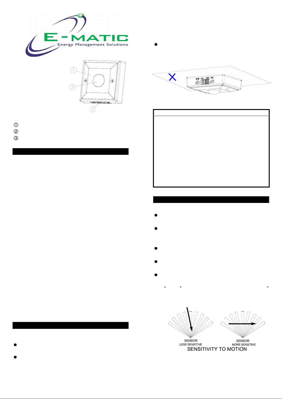
This
unit can
(
FIGURE 1
not be installed
)
on t
he
ceili
ng.
ES205
Main Body
Lens
Slide
INTRODUCTION
The PMWS 110 degrees Surface Mount
Switch
is a fully automatic indoor controller capable of
controlling up to 2
fluorescent lighting. It uses a passive infrared sensor
which reacts to changes in temperature emitted by the
motion of persons or objects passing through its
detecting area. When you enter the room, it turns
on automatically the light to which it is connected and
the light remains lit as long as the wall switch senses
any activity in the detection area. It however will
automatically turn off the light after the preset
time
has expired. During the day, the builtphotocell sensor saves electricity by deactivating the
light
.
The PMWS is a very handy device, which offers you
safety, security, convenience and energy saving. It
is also easy to install and is suitable for the following
places:
living room, family room, stairway
With this wall switch installed, you remove the
pr
a light switch, thus avoiding danger for the elderly,
infirm and children at night or in dark areas.
oblem of searching in a dark hallway or staircase for
Switch
000W
PIR
Wall
incandescent or 600W
turn-off
in
s, entrance hall
etc.
FIGURE
IMPORTANT
Some local building codes may require installation
of this product by a qualified electrician.
Check your local codes as they apply to your
situation. If the house wiring is of aluminum,
consult with an
methods.
Before proceeding with the installation, TURN OFF
THE POWER TO THE LIGHTING CIRCUIT AT
THE CIRCUIT BREAKER OR FUSE BOX TO
AVOID ELECTRICAL SHOCK.
CHOOSING A MOUNTING LOCATION
For the best results, fix you
surface,
Avoid aiming the motion sensor at pools, heating
vents, air conditioners or objects which may
change temperature rapidly.
Do not allow sunlight to fall directly on the front of
unit.
Try to avoid point
pets may be detected.
Prior to mounting, remember to position the
motion sensor so that a moving object cuts
across
(FIGURE 2)
electrician about proper wiring
1.2~1.5m
its beams, not directly towards them.
above the ground.
ing
1
r s
the unit
ensor on a solid
where the motion of
Note : Read this entire manual before you start to
install the system.
SAFETY PRECAUTIONS
Be sure to switch off power source before
installing.
Make sure that the power wiring comes from
circuit with an external miniature circuit breaker
not higher than 16A fo
or a suitable fuse.
r the short circuit protection
FIGURE 2
Page 2

1
I
NSTALLATION
The unit has a sensing angle of approx. 110° and
can detect up to 12 meters at the mounting height of
1.5 meter
meters. (FIGURE
or 6 meters at the mounting height of 1.2
3)
2
Connect the BLUE wire (Neutral wire) of power
cord
and lamp
Connect the
terminal bloc
to the terminal block N mark.
BROWN
k "LS" mark.
wire of lamp wire to the
(FIGURE 5)
2
FIGURE
5
FIGURE 3
Install an external wall switch adjacent to the power
source (FIGURE 4). This helps you isolate the
with ease. See OPERATION for further information.
WIRING INSTRUCTION
FIGURE 4
light
(4) Fit the
with two fixing screws provided. (FIGURE 6)
SETTING THE LIGHTING SYSTEM
(1) TEST MODE
Turn the Lux control and the Time control
counter-clockwise to the e
(FIGURE 7)
main body
to the wall box and secure it
FIGURE 6
dge-the TEST position
(1)
Switch off the power source or
switch.
(2)
Strip approximately 6-
of the wires
(3) Connect the BROWN wire (Live wire) of power
cord to the terminal block "L" mark.
8mm
from the power cord.
of the insulating part
external wall
FIGURE 7
Page 3

3
Turn the
on immediately and wait for about 1 minute
warm up the unit. After warming-up time ha
expired and the
walk test and the l
that the wiring was done properly and that the
l
ight
Walk through the coverage area. The
turn on for about 3 seconds when motion is
detected and turn off shortly after motion stops.
Wait for the
to test the sensor.
(2) SETTINGS
TIME ADJUSTMENT
The TIME adjustment controls how long the l
stay on after motion has been detected.
Adjust the TIME Control Knob clockwise to
the turn-off time (
counter
seconds mini
external
is working.
-clockwise to decrease the turn-off time (3
mum).
wall switch on, the
light
goes off, you may make a
ight
will turn on. This confirms
light
to turn off before moving again
40
minutes maximum) or
(FIGURE 8)
light
will turn
to
light
will
ight
will
incre
ase
O
PERATION
s
Automatic Operation
There is a
Slide the switch to AUTO position. (FIGURE 10)
When the sensor detects motion, the light
automatically turns on. The built-in photocell turns
the sensor off and on according to the light level
selected by the LUX adjustment.
slide
switch located
4
FIGURE 10
on base
of the
PMWS.
about 3sec about 40min
FIGURE 8
LUX ADJUSTMENT
The LUX adjustment determines at wha
l
ight
will start opera
AUTO
Provisionally turn the L
clockwise at the moon (dusk) position. (FIGURE 9) In
this provisional setting mode, the Motion Sensor
remains inactive during daylight. At dusk
find it is the LUX level you desired for operation,
simply set the LUX control knob to the position that
you tried satisfactorily.
mode
.
ting when you
FIGURE
UX
9
Control Knob to the edge
t light level the
set the sensor to the
when
you
Manual
Sliding
connected light. (FIGURE 10) By using this OFF
switch to turn off the light without using the external
wall switch, the
period when switching back to the AUTO mod
TROUBLESHOOTING
Light does not turn on
Confirm that you have made a correct wiring
connection .
Make sure th
Light remains on
Make sure the wiring connection is correct.
Check if the TIME setting is correct.
Others
The specification of protective shield shall
consult to local service agent.
Off
the switch to OFF position will turn off the
sensor won
at the lamps have not blown..
t enter 1 minute warm-
up
e.
Page 4

5
SPECIFICATIONS
Power Requirement
Lighting Load
Detection Angle
Detection Distance
Mounting Height
Wall Switch Control
Time Adjustment
Lux Adjustment
Warm Up Time
Protection Class
Protection Degree
Safety
Specifications are
Warning:
Do not dispose of electrical appliances as unsorted
municipal w
aste, use separate collection facilities.
AC 220 ~ 240V / 50Hz
Max. 2,000W Incandescent
or Max. 600W Fluorescent
Up to 110°
Height
subject to change without notice.
Up to 12m at 2
Height
Recommended 1
(
3.9
Auto/
Approx. 3 seconds to
minutes
Approx. 5
mode
About 1 min
Class I
IP44
CE, GS
6
at
~
4.9
Ft) Wall Mount
Off
~ 1000 Lux
I
A501110412R01
25°C
5°C
.2 ~ 1.5m
at 1.5
at 1.5
m
m
40
& test
Contact your local government for information
regarding the collection systems available.
If electrical appliances are disposed of in landfills or
dumps, hazardous substances can leak into the
groundwater and get into the food chain, damaging
your health and well-being.
E-Matic Energy Management Solutions,
4 Arkwright Court
Blackpool,
Tel: 01253 791888, Fax: 01253 791887,
Web site:
Email:
www.challenger.co.uk
sales.challenger@adivision.co.uk
, Fylde Industrial Estate,
Lancashire
, FY4 5DR.
,
 Loading...