

Page 1
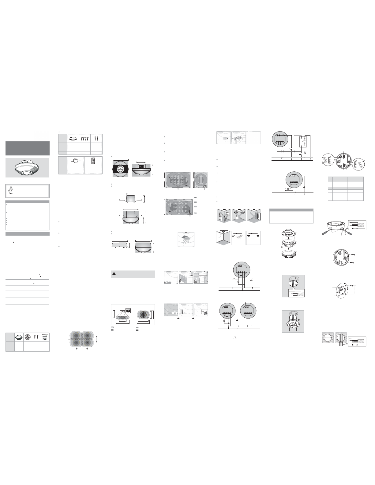
FIG.5-A
PIR Minor Motion
PIR Major Motion
Ultrasonic Minor
Motion
Ultrasonic Major
Motion
FIG.4-B
Open office
14m
8m
3.1.3 Examples of application
3.1.3.1 Ultrasonic sensor is less affected by humidity
which is more suitable for using in the moisty
environment (See FIG.5-A).
FIG.5-D
The shelves of
The cabinet. The stalls of
3.1.3.2 Ultrasonic sensor detects occupant based on
the Doppler Effect and it does not need to
“see” directly the movement of occupant. In
other words, it is able to detect the movement
happened behind the obstacles (See FIG.5-B
& FIG.5-C & FIG.5-D).
FIG.5-E
FIG.5-F FIG.5-G
3.1.3.3 Ultrasonic sensor is high sensitive in detecting
small movement, such as a minor motion of
typing, hand waving, door opening, etc. (See
FIG.5-E & FIG.5-F & FIG.5-G):
Light keeps off when
no movement is
detected.
Typing, light keeps
on.
Open the door,
light turns on.
3.1.4 Helpful tips for installation
Since the detector is in response to temperature,
airflow and wind change, please avoid the following
conditions:
Avoid aiming the detector toward the objects which
may be swayed in the wind, such as curtain, tall
plants, miniature garden, etc. (See FIG.6-A).
Avoid aiming the detector toward the objects
whose surfaces are highly reflective, such as
mirror, monitor, etc. (See FIG.6-A).
It is better to locate the detector at least 2m away
from the glass gate or window for avoiding
nuisance triggering because the shaking of glass
could trigger the ultrasonic sensor (See FIG.6-D).
FIG.5-H FIG.5-I
FIG.5-J
3.1.3.4 Since ultrasonic sensor is high sensitive to the
small motion and does not require a direct
view between the sensor and the movement,
therefore, it is optimum for using in the spaces
where frequently has less or small motion
taken place, such as a conference room, an
open plan office with partitions, a library, etc.
(See FIG.5-H & FIG.5-I & FIG.5-J).
D2 D1 N
N
L
Load
Power box
L
M/S R
Push button
(N.O.)
Manual
switch
Jumper
FIG.7
D2 D1 N LLN
N
L
Load
Power box
Power box
N
L
M/S R
S S
Push
button
(N.O.)
Master Slave
FIG.8
3.2.1.2 Master / slave operation (See FIG.8).
Jumper
It is better to locate the detector at least 2m away
from the source of airflow such as doorway, vents
and air conditioning, etc. (See FIG.6-B & FIG.6-C &
FIG.6-E). If airflow causes the detector false
triggering, set ACC knob to ON position. After that,
if the false triggering still exists, lower the ultrasonic
sensitivity or select a more suitable location.
The distance between two detectors must be at
least 2m to avoid interference (See FIG.6-F).
The direction of the ultrasonic sensor should aim to
the main detection area to obtain the best coverage
(See FIG.3).
FIG.6-E
>
2m
FIG.6-F
>
2m
FIG.6-D
>2m
Air
duct
3.2 Wiring
3.2.1 For lighting (With jumper wire on D1 & L
terminals).
3.2.1.1 One detector controls one load (See FIG.7).
FIG.6-BFIG.6-A FIG.6-C
Push button
(N.O.)
Push
button
(N.O.)
D2 D1 N
Power box
L
M/S R
Jumper
N
L
Ein
t
←
Staircase timer
Load
FIG.9
3.2.1.3 One detector controls staircase timer (Set
time knob to ) (See FIG.9).
1s.
3.2.2 For HVAC (Remove jumper wire on D1 & L
terminals) (See FIG.10).
D2 D1 N
N
L
Load
Power box
L
M/S R
Push button
(N.O.)
FIG.10
AC/DC
......
Presence Detector
PMUSC
INSTRUCTION MANUAL
TECHNICAL SPECIFICATIONS
ACC on / ACC
off Switch
Adjustable from approx. 5sec to
30min, Test &
Adjustable from approx. 10Lux to
1000Lux
Select “ON” for activating or select
“OFF” for deactivating air current
compensation function
1s.
Auto Off Time
Adjustment
Lux
Adjustment
230V~±10% 50/60HzRated
Voltage
PIR + US, PIR only, US only, PIR
or US
PIR: 360
o
circular, adjustable up
to Φ8m
US: 360
o
, adjustable up to 10m x
16m, it’s an oval shape
0
o
C to +45oC
Detection
Range
(H=2.5m)
Triggering
Method
selection
ClassⅡ, IP20
Operating
Temperature
Environmental
Protection
1
1
1
PACKAGE CONTENTS
22
Lens
shield
Detector
Pattern
Item
Quantity
Manual
Pattern
Quantity
1
Item
Junction
box JB-46
Accessories for optional purchase
2 PRODUCT DESCRIPTION
2.1 Features
The Dual-Technology presence detector PMUSC
integrates advanced PIR and Ultrasonic technologies
in one unit. The combination of these technologies
helps to eliminate false triggering problems even in
difficult applications. It is suitable for indoor
application which is ideal for using in home, openplan office, multi-stall public restroom, conference
room, under-ground parking lots, classroom, library,
etc.
4
Nondropping
screw
Φ3 x 18mm
US only or PIR/US:
When there is high level of minor motion or obstacle
(furniture or partitions) existing in the monitored
space, or it is a multi-stall space. For example, a
multi-stall public restroom, an office with partitions,
etc.
PIR+US:
If the precise detection is necessary, choose this
triggering method which can reduce the false
triggering problem. For example, a classroom, an
open-plan office, etc.
Triggering mode application examples:
With its knobs and IR remote controller, the time,
ultrasonic sensor sensitivity, Lux, ACC (air current
compensation) function and PIR/US triggering
method can be adjusted as user desired to match
different application requirements and energy saving
for switching light on and off.
2.2 Additional functions
2.2.1 Function of terminal R
Connect terminal R with push button (N.O. type) to
manually control the load’s on / off. When the load is
off, press (>1sec) the push button (N.O. type) to
manually switch the load on. The load keeps on if the
movement is detected constantly. The load can be
automatically switched off if no movement is detected
and the delay time has expired, or by pressing the
push button again. When the load is off, the movement cannot trigger the load on, and the detector will
return to the previous mode until detecting the last
movement and the delay time has expired. Refer to
FIG.7 for wiring connection.
PIR only:
If the monitored space is free of obstacle or has
high level of airflow or the detection area is needed
to be well specified. For example, a small-scale
office with air-conditioning, a small conference
room, etc.
FIG.1
2.2.2 Function of master / slave
14m
8m
20%
overlap
2.2.2.1 Compatible with slave detector to achieve
this function. PMUSC can connect up to
10pcs slave detector which has the same
detection range as PMUSCt o enlarge the
detection range. Under this mode, load and
LED perform according to the setting of the
master detector (PMUSC). Slave detector
works as a movement register to send signal
to master detector.
2.3 Dimension:
PMUSC: Φ111.5 x 67mm (See FIG.2-A)
2.2.3 Advance switching off function
To enhance energy savings, the detector is able to
turn off the controlled load prior to the set delay off
time if it detected the passing through occupant.
When the load is off, once the detector is triggered,
the load will keep on. If no movement is detected
again during 30sec to 3min, the load will on for
2.5min, and then off, even the time setting value is
more than 3min.
FIG.2-A
Φ111.5
52
67
JB-46: Φ111.5 x 35mm (See FIG.2-D)
FIG.2-C
FIG.2-B
FIG.2-D
FIG.2-E
35
Φ111.5
Φ111.5
72
Φ111.5
43.5
90
SP-96: 62.5 x 50mm (See FIG.2-B)
Detector with power box cap SP-96 for flush
mount:
Φ111.5 x 90mm
(See FIG.2-C)
Detector with junction box JB-46 for surface
mount: Φ111.5 x 72mm
(See FIG.2-E)
50
62.5
3 INSTALLATION AND
WIRING
Please disconnect power completely and read the
entire instruction manual carefully before
installation.
3.1 Select a proper location
FIG.3
Side view
US 16m
PIR 8m
2.5m
PIR Minor Motion
PIR Major Motion
Ultrasonic Minor Motion
Ultrasonic Major Motion
3.1.1 The recommended installation height of this
detector is 2 - 3m, and 2.5m is the optimal
mounting height. The detection range of PIR
sensor can reach up to Φ8m, and ultrasonic
sensor is an oval shape of 8m x 10m with small
movement (i.e. hand wave), and an oval shape
of 10m x 16m with large movement (i.e. walk).
The detection angle is 360° for both PIR and
ultrasonic sensors (See FIG.3).
Top view
US 10m
US 8m
360°
PIR
Φ4m
PIR
Φ8m
US 10m
US 16m
12m
7.5m
Classroom
Conference room
10m
8m
FIG.4-A
Dual-technology detector is capable of detecting
occupant without directly seeing the moving person
due to the high sensitivity of ultrasonic sensor.
Ceiling mount will give an overall view of the entire
room, and the detector should be mounted in the
center of the room so that the detector can detect
movement from anywhere of the monitored space.
If you choose the PIR technology (PIR+US or PIR
only) as triggering method, the detector should be
located where the PIR sensor is able to see the
occupant.
In order to ensure good reliability of PIR sensor, an
overlapping area is need to be considered while
installing several sensors in a space.
3.1.2 Location of dual-technology detector (See
FIG.4-A & FIG.4-B).
CAUTION!
Switches complying with this standard are
suitable for use at ambient temperature not
normally exceeding 25°C, but occasionally
reaching 35°C.
A circuit breaker (250VAC, 10A) type C according
to EN60898-1 shall be installed in the fixed wiring
for protection.
Do not mount on conductive surface.
Do not open the enclosure frequently.
Turn off power when change the light sources.
Bulb burn of certain brands would cause high inrush current which might damage the unit
permanently.
Installation and assembly of electrical
equipment must be carried out by skilled
person. Contact a qualified electrician
in the event of fault down.
Screw
Φ
3 x
14mm
2
Wood
screw
Φ
4
x 25.4mm
Pattern
Quantity
11
Item
PMUSIR
IR remote
controller
Power box cap
SP-96
+
U
LT
+
U
L
T
Time1
Time2
ON
ACC
OFF
ACC
PIR
/US
PIR
only
US
only
PIR
+US
IR-11T
Lux
Load (L )
Max. 10A (cosφ=1) for 250VAC
Max. 3A (cosφ=0.4) for 250VAC
Max. 5A for 30VDC
For lighting (with jumper wire):
For HVAC (remove jumper wire):
12 x (2 x 18W)
7 x (2 x 36W)
5 x (2 x 58W)
Energy saving Lamp: Max. 600VA /
400W (include
CFL and PL
lamp)
<
<
<
Incandescent Lamp: Max. 2000W
AC halogen Lamp : Max. 1000W
LV halogen Lamp : Max. 1000VA
(600W)
Fluorescent Lamp : Max. 900VA /
100μF
25 x (1 x 18W);
15 x (1 x 36W);
10 x (1 x 58W);
3.3.1.4 Assemble the detector with power box, then
fix them with two screws (See FIG.11).
3.3.1.5 Put on the decorative frame and restore the
power supply.
3.3.1.2 Pull out cables from European standard
junction box (See FIG.12), then strip off 6 8mm of cable sheathing for wiring, and refer
to the wiring diagrams for correct cable
connections (See FIG.7 - FIG.10).
FIG.12
mm8 - 6
3.3.1.3 Fit the power box into European standard
junction box then screw them with two screws
(See FIG.13).
FIG.13
3.3.1 Flush mount with European standard junction
box
3.3.1.1 Take off the decorative frame (See FIG.11).
FIG.11
Non-dropping
screw
Power box
Detector head
Decorative
frame
3.3 Installation Procedure
NOTE
The direction of the ultrasonic sensor should aim to
the main detection area to achieve the best
detection coverage when detector is flush mounted
with European standard junction box, and the fixing
plate can be adjusted 45°.
2.2.2.2 2.5mm
2
power cables for D1, D2, L, N
connection, and 1.5mm2 for master and slave
connection. Refer to FIG.8 for wiring
connection.
2.2.2.3 To get complete coverage in an open office
area, install multi slave detectors with approx.
20% overlap ultrasonic detection range to
adjacent ones (See FIG.1).
Dual-Technology
FIG.5-B FIG.5-C
W
RH % OK
RH %
OK
Dual-Technology
Presence Detector
PMUSC
3.3.2 Surface mount
3.3.2.1 There are 7 pairs of fixing holes with various
distances from 41mm to 85mm on the bottom
cover of the combined junction box JB-46
which can be selected for different mounting
applications (See FIG.14-A). To select two
same figures on both ends for the
corresponding fixing distance (See FIG.14-B).
FIG.14-A
80
80
8
5
8
5
7
0
7
0
6
0
6
0
63
63
53
53
41
41
80
80
8
5
85
7
0
70
60
6
0
63
63
53
53
41
41
A
B
Fixing holes
Fixing holes
FIG.16
80
85
70
60
63
53
41
80
85
70
6
0
63
53
41
FIG.17
Nondropping
screw
Nondropping
screw
3.3.2.4 Insert four non-dropping screws to the
corresponding screw holes on detector’s fixing
plate. Afterwards, those four screws will not
drop off to provide convenient subsequent
installation (See FIG.17).
3.3.2.5 Refer the FIG.11 to assemble the detector
head with the power box, and then refer to
the wiring diagrams (See FIG.7 - FIG.10) for
correct cable connections.
3.3.2.6 Put on the decorative frame and restore
power supply.
3.3.3 Flush mount
3.3.3.1 To install detector, please drill a hole with
diameter of 65mm on ceiling board and keep
the power cable outside. Please strip off 6 8mm of cable sheathing for wiring (See
FIG.18).
FIG.18
NO. A B
The distance
between A and B
1
2
3
4
5
6
7
41
53
60
63
70
80
85
41
53
60
63
70
80
85
41mm
53mm
60mm
63mm
70mm
80mm
85mm
FIG.14-B
FIG.15
3.3.2.2 To feed power cables through the side of
junction box, please use the cutting pliers to
break the side cable entry knockouts, then
insert cables into junction box and feed
through it. Please strip off 6 - 8mm of cable
sheathing for wiring (See FIG.15).
3.3.2.3 Choose two proper knockouts to fix the
junction box JB-46 on the surface of ceiling
board with two wood screws (See FIG.16).
30 - 35mm
6 - 8mm
Φ=65mm
30 - 35mm
6 - 8mm
Cable entry
knockout
Drill a hole with
Φ =65mm on the
ceiling
Page 2
Green
LED does
not turn
on
1. Ultrasonic
sensor is not
chose as the
triggering
method (US
only; PIR/US;
PIR+US).
2. Exceed the
valid detection
range.
1. Choose ultrasonic
sensor as the
triggering method.
2. The movement
should be in the
valid detection
range (10m x 16m).
Nuisance
triggering
There are heat
sources, airflow,
highly reflective
objects or any
objects which
may be swayed
in the wind within
the detection
coverage.
Avoid aiming the
detector toward any
heat sources, such as
air conditioning,
electric fans, heaters
or any highly reflective
surfaces. Make sure
there are no swaying
objects within the
detection coverage.
Lighting
device
does not
turn off
1. Auto off delay
time is set too
long.
2. Detector is
nuisance
triggered.
3. Incorrect
wiring.
1. Set auto off delay
time to a shorter
time and check if
the load is switched
off or not according
to the preset off
delay time.
2. Keep the objects
which may cause
nuisance triggering
away from detection
coverage to avoid
activating detector
while doing the test.
3. Refer to wiring
diagrams (See
FIG.7 - FIG.10).
Red LED
does not
turn on
1. PIR sensor is
not chose as
the triggering
method (PIR
only; PIR/US;
PIR+US).
2. Exceed the
valid detection
range.
1. Choose PIR sensor
as the triggering
method.
2. The movement
should be in the
valid detection
range (Φ8m).
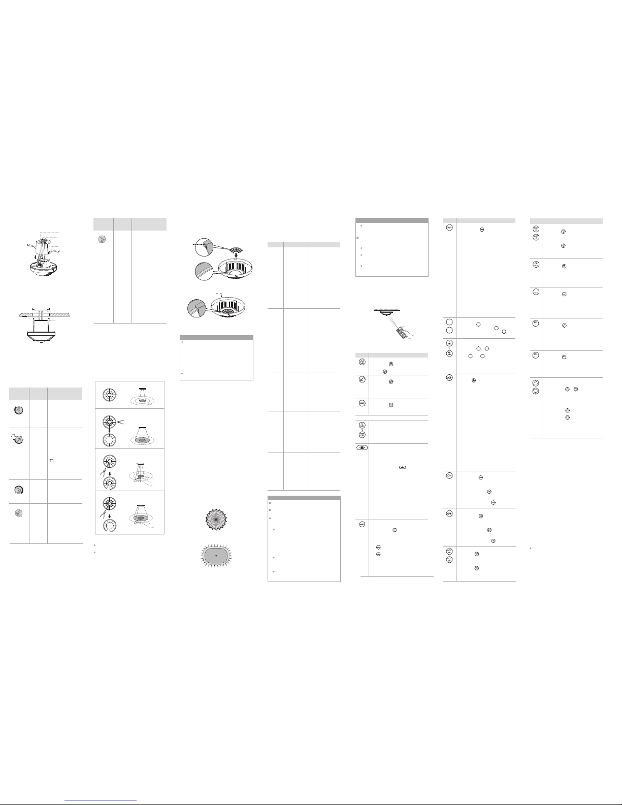
5
TROUBLE SHOOTING
Problem
Possible cause
Suggested solution
When PMUSC works abnormally, please check
assumptive problems and suggested solutions in
following table that will hopefully to solve your
problems.
Lighting
device
does not
turn on
1. Power does
not switch on.
2. Incorrect
wiring.
3. The ambient
light level is
too high.
4. Malfunctioned
load.
1. Switch on the
power.
2. Refer to wiring
diagrams (See
FIG.7 - FIG.10) and
check if the load is
malfunctioned.
3. Set Lux value
above the ambient
light level then
trigger the detector
and check if the
load is switched on
or not.
4. Replace the
disabled load with
a new one.
6 OPTIONAL ACCESSORY
FIG.24
PMUSIR
+
ULT
+
ULT
Time1
Time2
ON
ACC
OFF
ACC
PIR
/US
PIR
only
US
only
PIR
+US
IR-11T
Lux
NOTE
Wire connections in reverse in between N and
L will cause lower sensitivity of ultrasonic
sensor.
The following conditions may cause lower
sensitivity of PIR sensor:
On very foggy days, the sensitivity may be less
due to moisture collecting on the lens.
On very hot days, the sensitivity will be lower
as high ambient temperature can be close to
body temperature.
On very cold days when wearing heavy
clothing, and especially if the facial area is
covered, maybe appear less sensitive.
The Effects to PIR sensitivity:
NOTE
Do not attempt to open or repair the unit without
qualified electrician while it is malfunctioned.
Cleaning: Wipe with dry cloth only. Soap or
rough cloth may damage the detector lens.
The following conditions may cause lower
sensitivity or false triggering of ultrasonic sensor:
Set ACC knob to ON: The airflow will cause
false trigger to ultrasonic sensor. To reduce
the possibility of false trigger, the dual
technology sensor is designed with air current
compensation (ACC) function which is able to
reduce the sensitivity of ultrasonic sensor
approx. 10% ~ 40% varied with the strength of
airflow.
Ultrasonic sensitivity will be affected by the
materials such as carpet, sound absorbable
cotton, curtain, etc. since they are sound wave
absorber.
Low ambient temperature might slightly
decrease ultrasonic sensitivity and also reduce
the detection range.
The Effects to ultrasonic sensitivity:
All rig hts res erved . No repro ducti on, copy, o r
transmission of this priduct may be made without
writing permission.
1. Pressing “ ” button to activate the air
current compensation function which is
confirmed by the green LED keeping on
for 5sec.
2. Pressing “ ” button to deactivate the
air current compensation function which
is confirmed by the green LED flashing
for 5sec.
ACC on/off control function
1. By pressing “ ” button, load will be
switched off 8hrs, it is confirmed by
flashing of detector’s LEDs.
2. Exit off mode and return to Auto mode
either by pressing “ ” again or to re supply power to detector after it is off.
3. Load (for lighting control) can be lead to
on mode by pressing “ ” button under
off mode.
Load off
1. Press “ ” button to enter into short
impulse mode, both LED and load are
controlled by Lux under this mode.
2. If the triggering method is “PIR+US”:
Both PIR and ultrasonic sensors are
triggered, the load and LEDs will be on
for 1sec, and then off. The next trigger ing should be 9sec interval.
3. If the triggering method is “PIR/US”:
Either PIR or ultrasonic sensor is
triggered, the corresponding LED and
load will be on for 1sec, and then off.
The next triggering should be 9sec
interval.
4. If the triggering method is “PIR only”:
Only PIR sensor is triggered, the red
LED and load will be on for 1sec, and
then off. The next triggering should be
9sec interval.
5. If the triggering method is “US only”:
Only ultrasonic sensor is triggered, the
green LED and load will be on for 1sec,
and then off. The next triggering should
be 9sec interval.
6. LoadⅡhas no reaction in short impulse
mode.
Short impulse mode
1. By pressing “ ” button, load will be
switched on 8hrs, it is confirmed by
flashing of detector’s LEDs.
2. Exit on mode and return to Auto mode
either by pressing “ ” again or to re supply power to detector after it is off.
3. Load (for lighting control) can be lead to
off mode by pressing “ ” button under
on mode.
Load on
4.3.5 To repeat above mentioned procedures to
adjust the settings of detector either by knobs
or IR remote controller and conduct the walk
test until the detector’s detection coverage
meets your demand.
FIG.23-A
FIG.23-B
Walk type for PIR sensor
Walk type for ultrasonic sensor
4.2.3 Fixing lens shield: There is a circular groove on
the back of the decorative frame and the lens
shield is designed with a circular hook. By
coupling the hook into the groove, the lens
shield is fixed (See FIG.22-A & FIG.22-B).
FIG.22-A
FIG.22-B
Decorative frame
Circular
groove
Circular
hook
NOTE
4.3 Walk test (uncontrolled by Lux)
It takes approx. 30sec for detector to warm up
with load on after power is initially supplied or
resupplied after power failure, then the detector
enters into normal operation to carry out a walk
test. During which, red and green LEDs will
permanent on for 30sec if no IR setting value is
stored in detector. Reversely, the red and green
LEDs will flash for 30sec if any setting value has
been stored in the detector.
Re-supplied after power failure, detector works
according to the previous settings.
The purpose of conducting the walk test is to check
whether the triggering method (PIR, ultrasonic) is set
correctly or not and to adjust the detection coverage.
Procedures of conducting the walk test (Lux controller
is disabled):
4.3.1 Set the time knob to “Test” position.
4.3.2 Adjust the position of meter knob for matching
the sensitivity of ultrasonic sensor as you
desired. The detection coverage of PIR sensor
can be adjusted by using the lens shield.
4.3.3 Set the ACC knob to OFF position.
4.3.4 Select the desired trigger method (i.e. PIR+US,
PIR only, US only or PIR/US).
Step 1: Switch on the power supply and it takes
approx. 30sec for detector to warm up with
load and LED on for 30sec, afterwards they
will turn off.
Step 2: To walk within the desired detection coverage
of detector (Refer to FIG.23-A & FIG.23-B).
Step 3: When its PIR sensor is triggered by move ment, the red LED turns on for 2sec, then
turns off; when its ultrasonic sensor is
triggered by movement, the green LED turns
on for 2sec then turns off. When choosing
PIR+US as triggering method, both red and
green LEDs will turn on for 2sec then turn off
if both sensors have been triggered by move ment.
6.1 It is recommended warmly to purchase our high
quality IR remote controller PMUSIR for easy
convenient and safe operation on PMUSC.
Button Function
US
US
1. By pressing “ ” “ ” buttons to set
the sensitivity of ultrasonic sensor. Each
time the user presses the button, the
sensitivity of ultrasonic sensor would
increase or decrease 10% with
indication of green LED flashing.
2. By pressing “ ” button to increase the
sensitivity of ultrasonic sensor.
3. By pressing “ ” button to decrease
the sensitivity of ultrasonic sensor.
4. When the sensitivity of ultrasonic sensor
is at its highest or lowest level which is
confirmed by green LED keeping on for
approx. 2sec.
Sensitivity adjustment of Ultrasonic
sensor
US
US
US
US
US
By pressing “ ” button, the detector is
set to activate its load on only when the
ultrasonic sensor of it detects the movement, and the green LED will flash to
confirm the successful setting of this
mode. To exit this mode by selecting other
mode.
Ultrasonic only function
US
1. Pressing “ ” button to activate the air
current compensation function which is
confirmed by the green LED keeping on
for 5sec.
2. Pressing “ ” button to deactivate the
air current compensation function which
is confirmed by the green LED flashing
for 5sec.
ACC on/off control function
PIR only function
By pressing “ ” button, the detector is
set to activate its load on only when the
PIR sensor of it detects the movement,
and the red LED will flash to confirm the
successful setting of this mode. To exit this
mode by selecting other mode.
US
By Pressing “ ” button, the detector is
set to activate its load on when either PIR
sensor or ultrasonic sensor is triggered by
movement. When PIR is triggered, the red
LED will flash; when ultrasonic sensor is
triggered, the green LED will flash. To exit
this mode by selecting other mode.
PIR or Ultrasonic mode
US
US
By pressing “ ” button, the detector is
set to activate its load on when both PIR
sensor and ultrasonic sensor detect the
movement, and both red and green LEDs
will flash. To exit this mode by selecting
other mode.
PIR & Ultrasonic mode
US
Button Function
Time setting for Time / Time1 or
Time2
By pressing “ ” “ ” to select the load
desired to set the delay off time value.
Either “ ” or “ ” is pressed, LED
flashes 2sec, and then press the corresponding time value button to set it, which
is confirmed by 2sec flashing of
detector’s LED.
Time1
Time1
Time2
Time2
1. By pressing “ ” button to enter into
test mode. Both load and LEDs are
uncontrolled by Lux value.
2. If the triggering method is “PIR+US”:
Both PIR and ultrasonic sensors are
triggered, the load and LEDs will be on
for 2sec, and then off. The next trigger ing should be 2sec interval.
3. If the triggering method is “PIR/US”:
Either PIR or ultrasonic sensor is
triggered, the corresponding LED and
load will be on for 2sec, and then off.
The next triggering should be 2sec
interval.
4. If the triggering method is “PIR only”:
Only when PIR sensor is triggered, the
red LED and load will be on for 2sec,
and then off. The next triggering
should be 2sec interval.
5. If the triggering method is “US only”:
Only when ultrasonic sensor is
triggered, the green LED and load will
be on for 2sec, and then off. The next
triggering should be 2sec interval.
6. LoadⅡhas no reaction in test mode.
Test mode
Time2
Time1
Select load for time setting
By pressing “ ” to set the delay off
time value of loadⅠ, and “ ” to set the
delay off time value of loadⅡ. “ ” is
invalid if the detector has only one load.
Time2
Time2
Time1
Load for lighting control (Relay)
Lux value adjustments for lighting
control
By pressing corresponding button, the
selected light level threshold for
switching on the connected load can be
set.
By pressing “ ” button,PMUSIR is
unlocked; thereafter it can be used to make
settings. The PMUSIR will lock
auto-matically if there is no operation occurred
in 2min counting from the last operation.
By pressing “ ” button,PMUSIR can be
locked and no adjustments are workable
(except “ ” button).
Lock PMUSIR
Button Function
Unlock PMUSIR
Reset
By pressing “ ” button, detector is
controlled by potentiometers, and it can
delete all the MEMO data.
Automatic read-in of actual light
level function for lighting control
Actual light level can be read-in as
threshold for switching the corresponding light if the provided Lux values do
not match user's requirement. The steps
are as below: Push “ ” button till
detector's red and green LEDs flashing
to enter into learning mode, learning
time is 10sec. Then the ambient light
level is read in confirmed by LED on to
indicate IR learning successfully. Then it
returns to Auto mode. If the ambient
light level is out of the range of 5 1000Lux, detector will learn for 10sec,
then LEDs flash quickly for 5sec to
indicate IR learning unsuccessfully, but
below Lux value will be stored: 1000Lux
if the actual light level is above 1000Lux,
and 5Lux if the actual light level is below
5Lux.
1. By pressing “ ” button, both loads
and detector's LEDs have no reaction
if no settings are stored in PMUSIR.
2. When time of Time1, Time2 and Lux
are set by PMUSIR already, press
“ ” button more than 3sec to store
the settings successfully. By pressing
“ ” button less than 1sec, the stored
settings can be duplicated to a new
detector.
3. Remove the battery more than 5sec,
all the settings will be deleted. It needs
to be reset after replacing the battery.
Store and duplicate the values of
Time1, Time2, and Lux set by PMUSIR
6.2 Push button function:
Due to our policy of continuous improvement we
reserve the right to change specification without
prior notice.
Errors and omissions excepted. These instructions
have been carefully checked prior to publication.
However, no responsibility can be accepted by
E-Matic for any misinterpretation of these instructions.
E-Matic Energy Management Solutions
Distributed by: Challenger Security Products
10 Sandersons Way,
Blackpool, FY4 4NB
Tel: 01253 791888, Fax: 01253 791887
Email: enquiries.ematic@adivision.co.uk
www.e-matic.co.uk
Ematic_PMUSC_Instructions_Rev01
4.2 Usage of lens shield for PIR sensor
4.2.1 PMUSC has provided 2 lens shields for masking
the undesired detection area of PIR sens or.
One lens shield has 2 layers with 6 small units
each, and 30° of detection angle can be covered
by each unit. For example, to inst all the detector
at the height of 2.5m, the detection range ca n
reach to 2m diameter if the complete lens shield
has been used; and up to 6m diameter i f only
the A layer of lens shield has been used ( See
FIG.21-A & FIG.21-B).
4.2.2 After user choosing the desired dete ction area,
the needless lens shield should be removed
(See FIG.21-C).
Φ2m
A
B
FIG.21
30°
Φ6m
Φ8m
The shadow part of the lens shields in the FIG.21-A
& FIG.21-B & FIG.21-C is needed to be cut off.
The ultrasonic sensor is unaffected by the lens
shield.
Knob
(Ex-factory
setting)
Function Knob setting
4 OPERATION AND
FUNCTION
4.1 Setting of Lux, Time, Meter, ACC and
PIR/US knobs
Lux
1000
300
10
100
Set the
light value
for
switching
on load
Range: Approx. 10Lux
to 1000Lux
User can set the knob
according to their
requirement for
application. The marked
values are for reference
only.
Time
15m
5m
5s
30m
Test
1s.
Range: Approx. 5sec to
30min
Test: Test mode (Load
and red and/or
green LED will
2sec on, 2sec off).
Test mode is
uncontrolled by
Lux.
: Short impulse
mode for staircase
timer switch control
(Load and red and
/ or green LED will
1sec on, 9sec off).
1s.
Set delay
off time
Set the
sensitivity
of
ultrasonic
sensor
“
-” = Min. (Approx. an
oval shape of 2m x
3m).
“+” = Max. (Approx. an
oval shape of 10m
x 16m).
Meter
4x6m
7x8m
+
-
3.3.3.2 Break the two rubber gask ets on the power
box cap with screwdriver, then put the power
cable through them (See FIG.19).
FIG.19
Cable entry
P
ower box cap
Non-dropping
screw
Rubber gasket
3.3.3.3 Refer to wiring diagrams for correct cable
connections, then cover the power box cap
back and screw it tightly.
FIG.20
3.3.3.5 Switch on the power supply.
Φ=65mm
Power cable
Spring clips
ACC
OFF ON
Reduce
the false
trigger
problem
caused by
airflow.
ON : Activate the ACC
function.
OFF: Deactivate the
ACC function.
Remark: Under ACC ON
status, the
detection
coverage of
ultrasonic
sensor will be
reduced.
Knob
(Ex-factory
setting)
Function Knob setting
PIR only US only
PIR/US PIR+US
Select
triggering
method
PIR/ US: Load will turn on
when either PIR
or ultrasonic
sensor is
triggered.
PIR+US: Load will turn
on when both
PIR and
ultrasonic
sensors are
triggered, and
after the load is
on, either PIR
or ultrasonic
sensor detects
movement, the
load keeps on.
PIR only:Load will turn
on only when
PIR sensor is
triggered.
US only: Load will turn
on only when
ultrasonic
sensor is
triggered.
The whole lens shield is used.
Φ6m
30°
Φ6m
Φ8m
Φ2m
A layer of the lens shield is used.
Part of the lens shield is used.
Part of the lens shield is used.
3.3.3.4 Insert detector’s two spring clips into the
drilled hole, then push it upwards (See
FIG.20).
 Loading...