

Page 1
3.3.1.2 Staircase timer switch controlled by one sensor (Time1 should
be set to , See FIG.6)
3 INSTALLATION AND WIRING
FIG.2
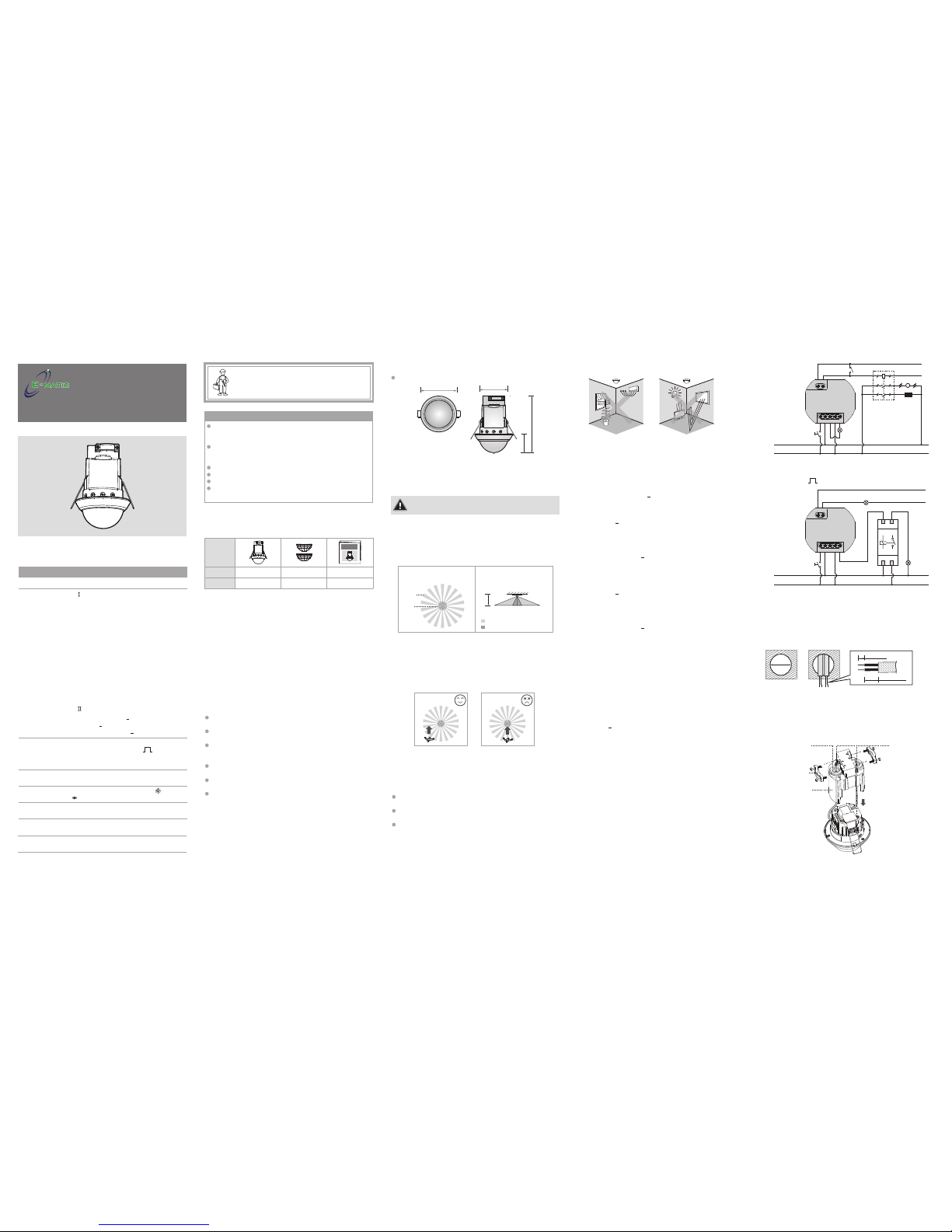
3.1.1 It can be installed at the height of 2 - 3m, it’s recommended to
install it at the height of 2.5m to gain the optimal detection
pattern, the detection range can reach up to the diameter of
20m and cover 360
o
detection angle (See FIG.2).
3.1.2 Pay attention to the walking direction in the test proceeding.
It is more sensitive to movement across the detector and less
sensitive to movement directly toward to detector which will
reduce the detection coverage (See FIG.3).
FIG.5
FIG.6
1s
2.2 Dimension
3.3.1.1 Normal operation (See FIG.5).
PMSCF20: Φ82 x 124.4mm (See FIG.1)
Top view
Side view
10m 10m
2.5m
2m 2m
Major Motion
Minor Motion
Φ20m
Φ4m
360
o
3.1 Select a proper location
Load
Operating
Temperature
Environmental
Protection
Class Ⅱ,IP44
Rated voltage 230V~±10% 50 / 60Hz
TECHNICAL SPECIFICATIONS
0oC to +45oC
INSTRUCTION MANUAL
Installation and assembly of electrical equipment must
be carried out by qualified electricians.
Contact a qualified electrician in the event of fault or
break down.
A circuit breaker (250VAC, 10A) type C according to
EN60898-1 of loadⅠshall be installed in the fixed wiring
for protection.
A circuit breaker (250VAC, 6A) type C according to EN60898-1
of loadⅡ(CH2) shall be installed in the fixed wiring for
protection.
Do not mount on conductive surface.
Do not open the enclosure frequently.
Turn off power when change the light sources.
High in-rush current would occure when bulbs of certain
brands burned which might damage the unit permanently.
CAUTION!
1 PACKAGE CONTENTS
PMSCF20 is a ceiling mount PIR detector. The load will be
switched on automatically when the movement is detected and
the ambient light level is below the Lux setting value; Until there
is no movement detected and the pre-set delay time has been
expired, load will be switched off automatically. User can pre-set
the desired Lux and Time values by VR setting for automatic
control lighting on / off with low initial cost and great energy
saving potential. PMSCF20 is also be used in many different
places for HVAC control. They can be widely used in home,
office, conference room, hotel, corridor, underground parking
lots, eaves, etc.
2 PRODUCT DESCRIPTION
Please disconnect power completely and read the entire
instruction manual carefully before installation.
3.2 Function
3.3 Wiring
3.3.1 PMSCF20
N N L L’R
Load
Push
button
(N.O.)
N
L
D2 D1
A1
A2
Supply
Voltage
Contactor
Fan
Heater
M
Manual
Switch
PMSCF20
PMSCF20
N N L L’R
D2 D1
Load
Staircase timer
Push
button
(N.O.)
N
L
LN
OUTIN
Load for
HVAC
Power supply
µ
FIG.3
More sensitive of movement
walking across the pattern
Less sensitive of movement
directly towards detector
Incandescent Lamp : Max. 2000W
AC Halogen Lamp
: Max. 1000W
LV Halogen Lamp
: Max. 1000VA / 600W
(traditional)
Max. 1000VA / 900W
(electronics)
Fluorescent Lamp
: Max. 1000VA / 600W
(uncompensated)
Max. 900VA / 100µF
25 x (1 x 18W); 12 x (2 x 18W);
15 x (1 x 36W); 7 x (2 x 36W);
10 x (1 x 58W); 5 x (2 x 58W)
LED Lamp
: Max. 500VA / 400W
Energy Saving Lamp: Max. 600VA / 400W
(include CFL and PL lamp)
Load
Ⅱ(CH2) For HVAC (Lux is invalid):
Max. 5A (cosφ=1) for 250VAC
Max. 5A for 30VDC
Max. 1A (cosφ=0.4) for 250VAC
<
<
<
LoadⅠ(CH1) For Lighting: µ
FIG.7
Φ=65
Drill a hole with
Φ=65mm on the
ceiling
6 - 8mm
30 - 35mm
To install detector, please drill a hole with diameter of 65mm on
ceiling board and keep the power cable outside. Please strip off 6 8mm of cable sheathing for wiring (See FIG.7).
3.4 Installation procedure
3.4.1 Ceiling flush mounting
3.2.2 ON / OFF delay function
According to the changeable ambient light level, detector can
postpone load’s delay time of turning on and off to avoid load’s
unnecessarily turning on or off due to rapid ambient light change:
Ambient light level changes from bright to dark: If the ambient
light level keeps be lower than the preset Lux value for 10sec, the light
will be automatically switched on after 10sec. (LED will be on 10sec
for indication)
Ambient light level changes from dark to bright: If the ambient
light level continuously exceeds the switch off Lux value for 5min, there
are different reactions according to the time setting value.
Time setting 5min, the light will be automatically switched off after
5min.
Time setting < 5min, the light will be automatically switched off when
the set time reached if no movement is detected during the 5min. But
if there is movement detected within the 5min, the time will be reset
upon detection and until 5min later, the light is switched off.
<
Under the light on status, the light can be manually switched off by
short pressing ( 1sec) the push button. During this operation mode,
once the detector is triggered by movement, the light keeps off within
the set switch off delay time. Until there is no movement detected and
the pre-set switch off delay time has reached, the detector resumes to
work according to the previous operation mode set by knobs.
To press the push button ( 1sec) during the light manual off period
will activate the manual light on function (working as the Case 2).
An additional push button can be connected between terminal R and
L for manual on / off operation (case 1: on → off; case 2: off → on).
While pressing push button ( 1sec):
3.2.1 Manual on / off switching by using push button to activate
R terminal
<
<
<
Under the light off status, the light can be manually switched on by
short pressing ( 1sec) the push button. During this operation mode,
once the detector is triggered by movement, the light keeps on within
the pre-set switch off delay time. Until there is no movement detected
and the pre-set switch off delay time has elapsed, the detector resumes
to work according to the previous operation mode set by knobs.
To press the push button ( 1sec) during the light manual on period
will activate the manual light off function (working as the Case 1).
<
<
Case 1: Manual off switching (Lux setting is invalid):
Case 2: Manual on switching (Lux setting is invalid):
Pattern
Item
Quantity
Detector
1
Manual
12
Lens shield
PRESENCE DETECTOR FOR
LIGHTING AUTOMATION
CONTROL
PMSCF20i / PMSCF20Ai
FIG.1
Φ82
124.4
41.8
Φ65
FIG.8
Non-dropping
screw
Rubber gasket
Protection cap
Cable clamp
3.4.2 Use screwdriver to loose two screw take down the protection
cap and take out the cable clamp from it.
3.4.3 Break the rubber gasket, then feed cables through it (See
FIG.8).
PMSCF20
20m 2 Channel Flush Occupancy Sensor
Auto Off Timer
Adjustment
Lux
Adjustment
360
o
circular, up to Φ20m at height of 2.5m
Detection
Range
1s
Time 1 (for lighting): Adjustable from approx.
5sec to 30min, Test &
Time 2 (for HVAC): Adjustable from approx.
10sec to 60min
Meter
Adjustment
Adjustable from “-” (approx. Φ10m) to “+”
(approx. Φ20m)
Adjustable from approx. 10Lux to (∞) and
“ ” (learning range: 10Lux - 2000Lux)
2.1 Features
Integrated sensor and power box in one united using the spring
clamps for easy and quick installation.
Two relays for controlling lighting and HVAC device
respectively (PMSCF20 only).
Built-in walk test function to ensure the desired detection field
is entirely covered and a red LED is built-in for testing
triggering indication.
Ambient light level can be learned as the threshold for switching
on / off the loads for more flexible application.
Lens shield for minimizing or blocking detecting field as user
desired.
Additional function of manually switching on / off the controlled
load is available by connecting with a push button switch.
W
FIG.4-A
FIG.4-B
3.1.3 Helpful tips for installation
Avoid aiming the detector toward the objects which may be swayed
in the wind, such as curtain, tall plants, miniature garden, etc.
Avoid aiming the detector toward the objects whose surfaces are
highly reflective, such as mirror, monitor, etc.
Avoid mounting the detector near heat sources, such as heating
vents, air conditioning, vents as dryers, lights, etc.
Since the detector is in response to temperature change, please avoid
the following conditions (See FIG.4-A & FIG.4-B):
Page 2
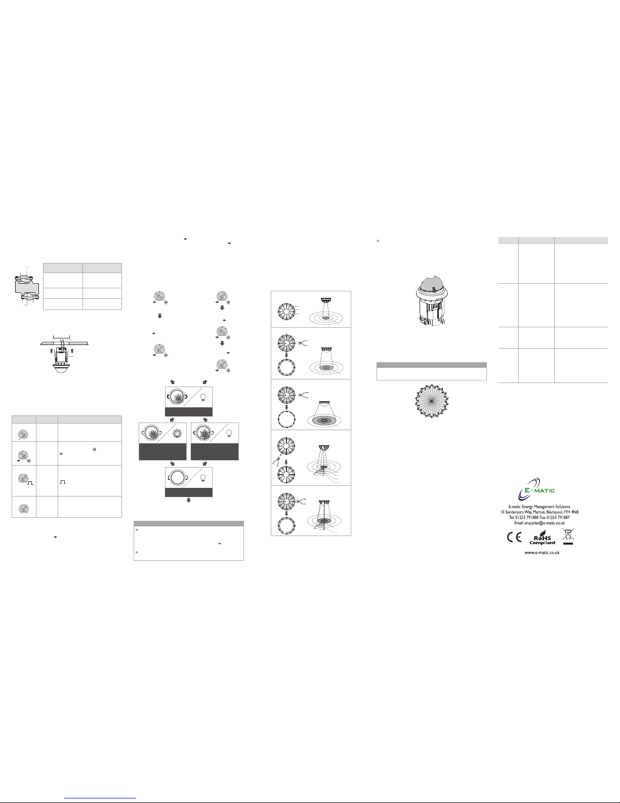
4.3.1 PMSCF20 has provided 2 lens shields for masking the undesired
detection area. Each lens shield has 3 layers (Layer A / Layer B
/ Layer C), each layer includes 6 small segments and each small
segment can cover 30° detection angle. For example, to install
the detector at the height of 2.5m, the detection range can
reach up to 4m diameter if the complete lens shields has been
used, and up to 8m diameter if layer C has been cut, as well,
up to 14m diameter if layer B also has been cut, the detection
range can reach up to 20m diameter when no lens shield is
used.
4.3 Usage of lens shield
Problem Possible cause Suggested solution
Lighting
device
does not
turn on
1. Power does not
turn on.
2. Wired incorrectly.
3. Lux knob adjusted
incorrectly.
4. Malfunctioned
load.
1. Switch on the power.
2. Refer to wiring diagrams for
correct connection.
3. Check if Lux knob is set to
the correct position.
4. Replace the disabled load
with a new one.
Lighting
device
does not
turn off
1. Auto off time is
set too long.
2. Detector is
nuisance
triggered.
3. Wired incorrectly.
1. Set auto off time to a shorter
time and check the load is
switched off or not according
to the pre-set off time.
2. Keep away from detection
coverage to avoid activating
detector while doing the test.
3. Make sure load and wires
are connected correctly.
LED does
not turn
on
1. Time konb is not
set to Test.
2. Exceeding the
detection range.
1. Time knob must be located
to Test position.
2. Walk in the effective detection
range of 20m diameter.
Nuisance
triggered
There are heat
sources, highly
reflective objects or
any objects which
may be swayed in
the wind within the
detection coverage.
Avoid aiming the detector
towards any heat sources, such
as air conditionings, electric
fans, heaters or any highly
reflective surfaces. Make sure
there are no swaying objects
within the detection coverage.
4.3.2 Fixing lens shield: There is circular hook on the back of the
decorative frame and the lens shield is designed with a circular
groove. The lens shield can be fitted by joining the groove of
lens shield with its corresponding hook on the decorative frame
(See FIG.13).
FIG.12
FIG.14
FIG.13
4.4 Walk test
The purpose of conducting the walk test is to check and adjust the
detection coverage. Set Time knob to “Test”, then conducting a walk
test and Lux is disabled.
It takes approx. 60sec for detector to warm up after power is
supplied, then enters into normal operation to conduct a walk test.
NOTE
4.4.1 Tester must be within the detection coverage.
4.4.2 Switch power on.
4.4.3 PMSCF20 takes approx. 60sec to warm up with load and LED
on, then turns off after warming up time.
4.4.4 Walk from outside across to the detection pattern until LED
turns on for approx. 2sec then off, the next trigger should be
2sec interval (See FIG.14).
4.4.5 Adjusting lens shield for desired detection range.
4.4.6 Repeat step 4.4.4 and 4.4.5 until it meets user's demands.
Test procedure
5 TROUBLE SHOOTING
When PMSCF20 works abmormally, please check assumptive
problems and suggested solutions in following table that will hopefully
to solve your problem.
Φ4m
C
B
A
The whole lens shield is used.
Part of the lens shield is used.
30°
Φ20m
Φ8m
Part of the lens shield is used.
Φ14m
Φ20m
Φ4m
Φ8m
30°
Φ8m
A & B layers of the lens shield are used.
A layer of the lens shield is used.
Φ14m
The shadow part of the lens shields in the FIG.12 is refer to the
cut off parts.
NOTE
When the actual light level is out of the range 10 - 2000Lux,
detector will learning 25sec, then the red LED flashes quickly for
5sec. When the actual light level is below 10Lux, Lux value is set
to 10Lux, or is above 2000Lux, Lux value is set to
∞
(uncontrolled by lux setting).
Installer should be away from the detector to avoid affecting the
luminous flux that reaches the detector when learning Lux value.
10
300
100
2000
10
300
100
2000
10
300
100
2000
10
300
100
2000
10
300
100
2000
Adjust knob to
” “ from
other position
Adjust knob to
other position
from ” “
1sec after goes
back to ” “
FIG.11-A
FIG.11-B
LED flashes slowly for 25sec
& Load is off
W
W
W
W
LED and load off
Detector switches to AUTO
mode
LED flashes quickly for 5sec &
Load is off (the actual light
level range is out of 10 2000Lux)
LED and load keep on 5sec
(the actual light level range
is 10 - 2000Lux)
FIG.11-C
28-MLCHA420P-C
4.2.2 When the knob is set to “ ” originally, it should be adjusted
to other position more than 1sec, then goes back to “ ” (See
FIG.11-B).
4.2.3 Then the load is off. LED starts to flash slowly indicating entering
into learning mode. Learning will be completed within 25
seconds. Afterwards, the LED and load will keep on 5sec or
LED flashes quickly for 5sec and load is off to confirm successful
learning (See FIG.11-C).
4.2.4 After learning procedure, the detector returns to AUTO mode
with LED and load being off.
3.4.7 Restore the power supply.
FIG.10
Φ65mm
Power cable
Spring clips
3.4.6 Close up sensor’s two spring clips and insert sensor into the
drilled hole on ceiling (See FIG.10).
3.4.4 Please refer to illustration of FIG.5 - FIG.6 for correct wiring
and then screw the protection cap tightly and fit on the cable
clamp.
3.4.5 Each cable clamp have two groves, then can fitup the different
of diameter of cable (See FIG.9).
Big grovle
Big
grovle
Small grovle
Small
grovle
Big
grovle
Small
grovle
FIG.9
Connect a circular
cable of Φ5 Φ12.5mm
Connect two circular
cable of
Φ5 - Φ6mm
Connect a circular
cable of Φ3 - Φ5mm
Connect two circular
cable of
Φ3mm
Connect one or two
flat cable of 4 x 8mm
Range: Approx. 10sec to 60min
(Reaction is regardless of
Lux value)
Set delay
off time for
HVAC
Time 2
15m
10s 60m
30m
Set delay
off time for
lighting
Range: Approx.5sec to 30min
Test
: Test mode (Load and red LED
will be 2sec on, 2sec off)
: Short impulse mode for
staircase timer switch control
(Load will be 1sec on, 9sec off)
1s
Time1
5m
5s 30m
Test
15m
1s
4.1 Meter, Lux, Time1 and Time2 knob
Knob Function Knob setting
4 OPERATION AND FUNCTION
Meter+Set the
range of
sensitivity
Range: from “-”(Φ10m) to “+”
(Φ20m)
Lux
10
300
100
2000
Set the light
value for
switching
on load
Range : Adjustable from approx.
10Lux to “ ” (∞).
(learn): The actual ambient light
level (10 - 2000Lux) can
be read in.
Learning procedure:
4.2 Lux learning function with knob
4.2.1 Adjust the knob to “ ” when the ambient light level matches
with the desired value (See FIG.11-A).
 Loading...