

Page 1
PMSCF Instructions Rev02
MODEL: PMSCF
INSTALLATION AND OPERATING INSTRUCTIONS FOR CEILING PIR SENSOR
Thank you for choosing PMSCF PIR sensor. This sensor is suitable for INDOOR use only. Please read these instruction before
installation and keep for future reference.
IMPORTANT: Installation must be performed by a skilled/competent person who is familiar with the appropriate standards and
technical requirements of the appliance and its proper installation.
Never modify the unit, there are no user serviceable parts inside. Not suitable for use with dimmer switches. Install in accordance
with IEC Wiring Regulations.
■ POSITIONING THE UNIT
When selecting the mounting position, please take the following points into account:
1.
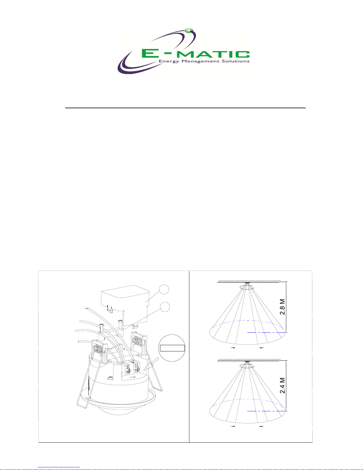
The sensor is designed for optimum performance to be mounted on the ceiling (see Figure 2)
2.
Ensure that the sensor cannot pick up or is close to heat sources such as heater or heat extraction units, which may cause
false triggering.
3.
If you set the Lux control level to night (), ensure that the sensor cannot detect bright light as that the unit will not work.
4.
Do not fit the sensor near strong electromagnetic fields as false activations may occur.
■ FITTING THE UNIT (See Figure 1)
Before any electrical work, ensure mains supply cables is isolated by switching off and removing the relevant fuse.
1. Drill a circle hole of around 2.5-inch (63.5mm) diameter in the ceiling where you are to mount the sensor
2. Remove the terminal cover ① and unscrew the cable clamp ② (see Figure 1)
3. Connect the main supply cable to the corresponding terminals
Figure 1
Black(Load)
Blue(Load)
1
2
Blue (Main
power Neutral)
Brown (Main
power Activel)
L
N L
out in
i
n
out
L
N
L
Ceiling
360°
RadiusMax 4.5M
Max 4.5M
360°
Ceiling
RadiusMax 4M
Max 4M
Detection Area
Figure 2
Page 2
PMSCF Instructions Rev02
4. Secure the cable by re-screwing the cable clamp. Fix the terminal cover back
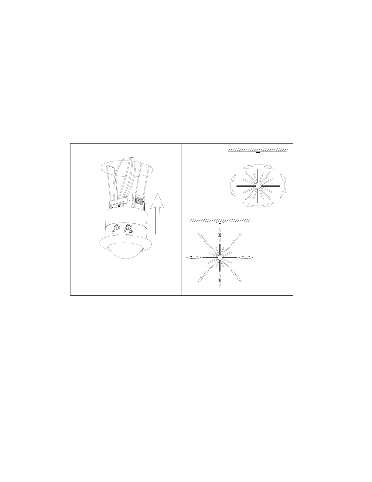
5. Press the side springs up, hold them and mount the sensor into the ceiling hole (see Figure 3)
After finishing the fitting operation, you can adjust the detection area and working state of PIR sensor
■
OPERATION MODE:
WALK TESTING:
When the mains supply is switched on to the PMSCF, the PMSCF sensor will enter into a “WARM-UP” period for approximately 1
minute and then automatically change to “AUTO MODE”. While sensor is in the AUTO MODE, you can then carry out a Walk-Test
by placing the LUX control to day position () and the TIME control to minimum (-). Once the PMSCF sensor receives a valid
trigger signal (such as movement of a person) within its detection area, the lamp(s) (load) will be turned on for the pre-set period
of time. You will be able to determine the detection area by walking slowly.
Please Note: Movement across the detection area is more effective than movement directly toward or away from the sensor.
(Refer Fig.4A). If movement is towards or away from the sensor, not across, the detection range will be reduced. (Refer Fig. 4B)
After completing the walk-test, set the LUX DIAL to the required night position to ensure PMSCF only operates at night or
required light level and set TIME DIAL to the desired “ON’ time.
ADJUSTING THE LUX CONTROL LEVEL:
The Lux control module has a built-in photocell that detects daylight and darkness.
() position denotes that the lamp(s) (load) will be turned on by PIR during day and night.
( ) position denotes that the lamp(s) (load) will be turned on by PIR only at night.
You can set to operate the unit at the desired level by adjusting the LUX knob
ADJUSTING THE DURATION TIME:
The duration time is “the length of time that the PMSCF switches the load ‘on’ after activation”. The duration time can be adjusted
from (10±5) seconds to (30±3) minutes. Rotating the TIME knob from (+) to (-) will reduce the duration time.
Note: Once the lamp(s) (load) has been triggered by the PIR sensor any subsequent detection will start the timed period again
from the beginning.
■ ATTENTION:
1. Before any electrical work, ensure mains supply cable is isolated by switching off and removing the relative fuse.
2. There are not any servicing parts inside, do not attempt to modify or service the unit.
3. It is normal that the load will delay several seconds to be turned on when power on.
Fig. 4(B) Not
Good
Fig. 4(A)
Good
Figure 3
Page 3

PMSCF Instructions Rev02
■ IMPORTANT:
Never attempt to remove the lens cover as this will damage the sensor and render all guarantees invalid.
■ TECHNICAL DETAILS:
Voltage:::: 220 -240VAC 50 Hz
Wattage:::: Max. 2000W incandescent bulb (resister-load) or 600W fluorescent load,
LED 60W-200W (depends on
different quantity LED driver)
Detection range: 360°, radius 4.5 meters with installation height of 2.8 meters
Duration time:::: From (10±5) seconds to (30±3) minutes adjustable
Lux control level: From daylight to night
Due to our policy of continuous improvement we reserve the right to change specification without prior notice.
Errors and omissions excepted. These instructions have been carefully checked prior to publication. However, no responsibility can
be accepted by E-Matic for any misinterpretation of these instructions.
E-Matic Energy Management Solutions
10 Sandersons Way, Marton,
Blackpool, FY4 4NB
Tel: 01253 791888, Fax: 01253 791887
Email: enquiries.ematic@adivision.co.uk
Web: www.e-matic.co.uk
 Loading...