

Page 1
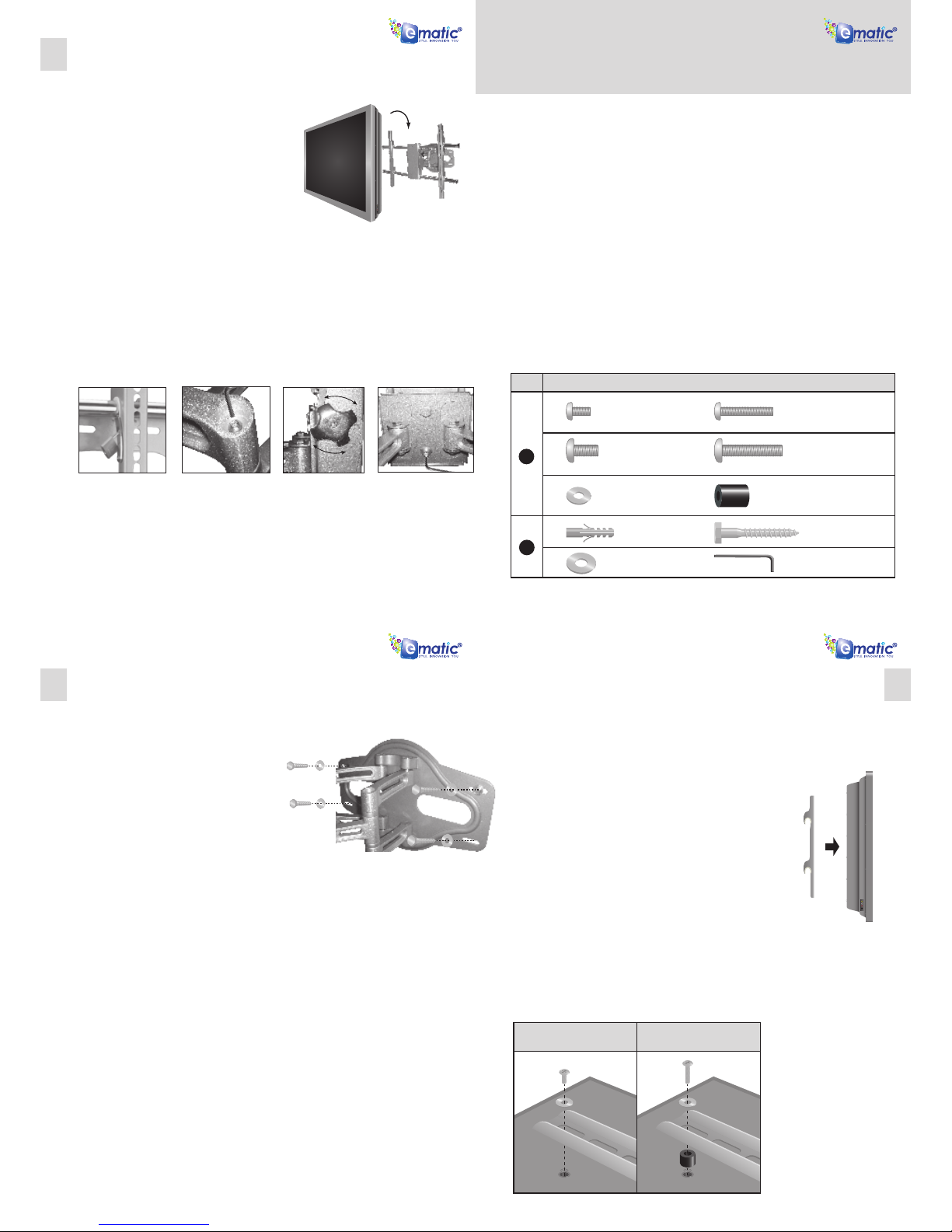
Part 2 – Attaching the Arms to the Display
Important! ! Use extra care during this par t of the installation. If
possible, avoid placing your display facedown as it may damage
the viewing surface.
NOTE: Your mount comes with a selection of bolt diameters and
lengths to accommodate a wide variety of display models. Not
all of the hardware in the kit will be used.
1. Determine the correct length of bolt to use with your display by
rst examining the back of your display.
A. If your display has a at back, you will use one of the shorter
bolts (A or C) from the hardware kit.
B. If your display has a curved or recessed back, you will use one
of the longer bolts (B or D) along with a spacer (F).
2. Determine the correct diameter of bolt to use by carefully trying
one bolt each from Bag 1 of the hardware kit. Do not force any
of the bolts – if you feel resistance stop immediately and try a
smaller diameter bolt.
3. Attach the arms to the back of your display using the bolts
identied in Steps 1 and 2 along with the corresponding Lock
Washer (E) (see Fig. 2 and 3).
A. If you are using the M6 bolts you will also need to use the M6
Washers (E).
B. If you are using one of the longer bolts on a display with a
curved or recessed back, you will also use a Spacer (F).
4. Make sure all screws are secure, but do not over-tighten them.
32
Part 1a – Mounting the Wall Plate
(Drywall)
Important! For safety reasons, this mount must
be secured to two adjacent wood studs at
least 16” apart. The studs must be capable of
supporting the combined weight of the
mount and display.
1. Using a stud nder, locate and mark two
adjacent studs for securing the mount.
2. With the help of another person, place the
mount against the wall and level it using the
bubble guide.
3. While another person holds the mount in
place, mark four locations (two per stud) on
the wall where the mount is to be installed. Be
sure to use the center of each stud.
4. Set the mount aside and drill a 1/4” (6 mm)
pilot hole at each marked location.
5. Place the mount back against the wall and
secure it using the Lag Bolts (H) and Lag Bolt
Washers (I) provided (see Fig. 1). Do not overtighten these bolts and do not release the
mount until all bolts are in place.
Part 1b – Mounting the Wall Plate (Concrete)
Important! For safety reasons, the concrete wall must be capable of supporting the combined
weight of the mount and display.
1. With the help of another person, place the mount against the wall and level it using the bubble
guide.
2. While another person holds the mount in place, mark four locations on the wall where the mount
is to be installed.
3. Set the mount aside and drill a 7/16” (11 mm) pilot hole at each marked location. Remove any
excess dust from the holes.
4. Insert a Concrete Anchor (G) into each hole so that it is ush with the concrete surface. A hammer
can be used to lightly tap the anchors into place if necessary.
NOTE: If the concrete wall is covered by a layer of plaster or drywall, the concrete anchor must
pass completely through the layer to rest ush with the concrete surface.
5. Place the mount back against the wall and secure it using the Lag Bolts (H) and Lag Bolt Washers
(I) provided (see Fig. 1). Do not over-tighten these bolts and do not release the mount until all
bolts are in place.
Fig. 1 - Attach the wall plate to the wall.
Tools Required
Phillips Head Screw Driver
Ratchet or Driver with 1/2” (13 mm) Socket
Electric Drill
1/4” (6 mm) Drill Bit and Stud Finder for Drywall Installation
7/16” (11 mm) Masonry Bit for Concrete Installation
Warnings
1. Make sure these instruc tions are read and thoroughly understood before attempting installation. If
you are unsure of any part of this installation, contact a professional installer for assistance.
2. The wall or mounting surface must be capable of supporting the combined weight of the mount and
the display; otherwise the structure must be reinforced.
3. Safety gear and proper tools must be used. Failure to do so can result in property damage and/or
serious injury.
4. A minimum of two people are required for this installation. Do not attempt to install this mount alone
under any circumstance.
5. Follow all instructions and recommendations regarding adequate ventilation and suitable locations
for mounting your display. Consult the owner‘s manual for your display for more information
Hardware Kit
EMW5001
© Copyright 2006-2007. All rights reserved.
Fig. 4 - Carefully hook the display onto
the wall plate.
Part 3 – Final Installation and Adjust-
ment
1. With the help of another person, carefully lift your
display and place it on mount (see Fig. 4). Place
the display in the middle of the mount, and do
not release the display until the mounting arms
have securely hooked onto the crossbars.
2. Move the safety tab located on each arm into
position to avoid having the display accidentally
lifted from the mount. A padlock can be inserted
into one of the tabs to help prevent theft of your
display (see Fig. 5).
3. The cable management clips can be used to keep
your power cord and other cables in order.
4. Side-to-side and front-to-back adjustments can
be made by rmly grasping your display and
carefully moving it to the desired position.
5. If any of the arms become too lose to hold their
position, they can be tightened using the Allen
Key (J) provided in your hardware kit (see Fig. 6).
4
For displays with at
backs...
For displays with curved
or recessed backs...
Fig. 2 - Attach the arms to the back
of your display.
Fig. 3 - Use a longer bolt and spacer for
displays with curved or recessed backs.
Do not use the M6 Washer (E) if you are
using the M8 Bolts (C or D).
Articulating LCD/Plasma Wall Mount
Installation Instructions
6. To adjust the tilt position of your display, have one person hold the display in place while
another person loosens the two tilt adjustment knobs located on either side of the mount
(see Fig. 7). Once the knobs are loose, move the display to the desired angle. Tighten the
knobs securely before releasing the display.
7. If you nd that your display is not level, rst loosen the horizontal adjustment screw located
behind the mount (see Fig. 8) using the Allen Key provided in your hardware kit. Carefully
level your display and re-tighten the adjustment screw.
Fig. 5 - A small padlock
can be used to help
prevent theft of your
display.
Fig. 6 - Use the Alley Key
to tighten the arms and
prevent unwanted
movement.
Fig. 7 - Loosen the
adjustment knobs to
change the tilt angle.
There is one knob on
each side of the mount.
Fig. 8 - Use the Alley Key to
loosen the horizontal
adjustment screw and level
your display.
Bag # (Ref ) Item (Qty)
1
2
(A) M6x12 Bolt (x4) (B) M6x30 Bolt (x4)
(C) M8x12 Bolt (x4) (D) M8x30 Bolt (x4)
(G) Concrete Anchor (x4) (H) M8x63 Lag Bolt (x4)
(F) 10mm Spacer (x8)(E) M6 Washer (x4)
(I) Lag Bolt Washer (x4)
(J) S4 Allen Key (x1)
 Loading...