

Page 1

WORKSHOP MANUAL
Chainsaw
GS35 – GS350 – MT350 – MT3500
Page 2

General failures’ analysis
GS35 – GS350 – MT350 – MT3500 chainsaws
Page 3

Suggested tools
General failures’ analysis
I.
II .
II I. Electronic tachometer: for 2 and 4 stroke engines, measurement range from 100 to 30,000 RPM
I.
Emak tool kit
Compression tester: to check thermal group
II.
p/n 3055125
III.
p/n 001000785
GS35 – GS350 – MT350 – MT3500 chainsaws
p/n 001000392A
Page 4

Index
General failures’ analysis
1) Performance
a) Compression test
b) Cylinder and piston inspection
c) Cylinder and piston assembly
d) Cooling system cleaning
e) Muffler inspection
2) Fuel system
a) Fuel and fuel filter inspection
b) Fuel system test
c) Tank breather inspection
d) Engine seal test
e) Manifold inspection
3) Ignition system
a) Starter housing inspection
b) Spark plug inspection
c) Spark test
d) Flywheel-coil air gap inspection
e) Flywheel key inspection
4) Oil pump, bar and shock absorber
a) Oil tank breather inspection
b) Sprocket inspection
c) Chain brake inspection
d) Oil pump and oil filter inspection
e) Worm gear inspection
f) Shock absorber replacement
g) Lubrication and bar maintenance
5) Tuning
a) Air filters inspection
b) Needle valve inspection
c) Carburetor inspection
d) Suggested tools for carburetion setting
e) Carburetion tuning
6) Tightening torques
7) Trouble shooting
a) The engine does not start
b) Low performance
c) Additional problems
GS35 – GS350 – MT350 – MT3500 chainsaws
Page 5
1) Rendimento
General failures’ analysis
a) Compression test
b) Cylinder and piston inspection
c) Cylinder and piston assembly
d) Cooling system cleaning
e) Muffler inspection
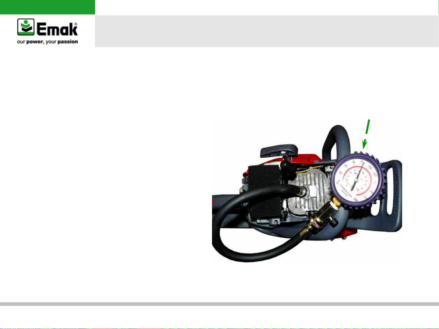
a) Compression test
•
Apply the Emak compression
tester (I) on cylinder. Pull
energetically the rope 10 times
•
Verify that the compression
value in not less than 7,5 bar –
110 psi
•
If the value in higher than
7,5 bar – 110 psi, start
inspection d), if lower, carry on
with inspection b)
I
p/n 001000392A
GS35 – GS350 – MT350 – MT3500 chainsaws
Page 6
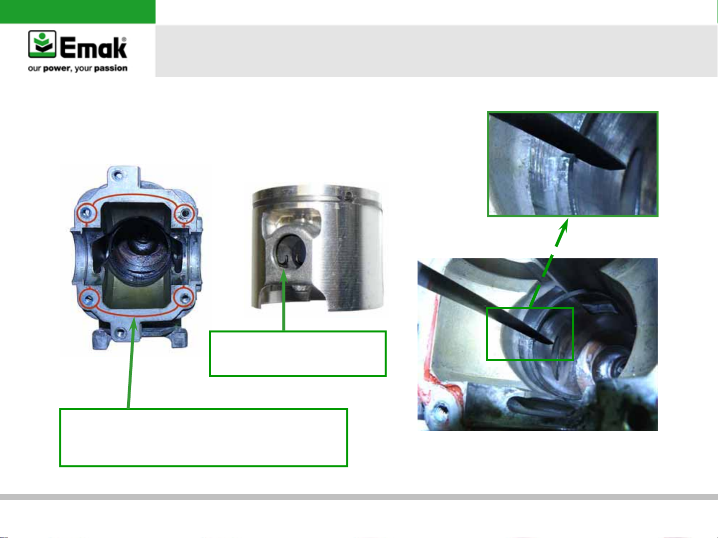
b) Cylinder and piston inspection
•
Verify the diamond scoring on piston and the nickel-lining on cylinder.
Replace if necessary
•
Verify the piston rings wear using feeler gauge (gap max 1,0 mm)
Warning: during assembly
make sure the circlip has the
feet pointing up
General failures’ analysis
Attention: de-grease the contact surfaces of the
cylinder and the cover. Use a liquid gasket to re-seal,
be careful with the quantity so it does not pollute
internal engine parts
GS35 – GS350 – MT350 – MT3500 chainsaws
Page 7
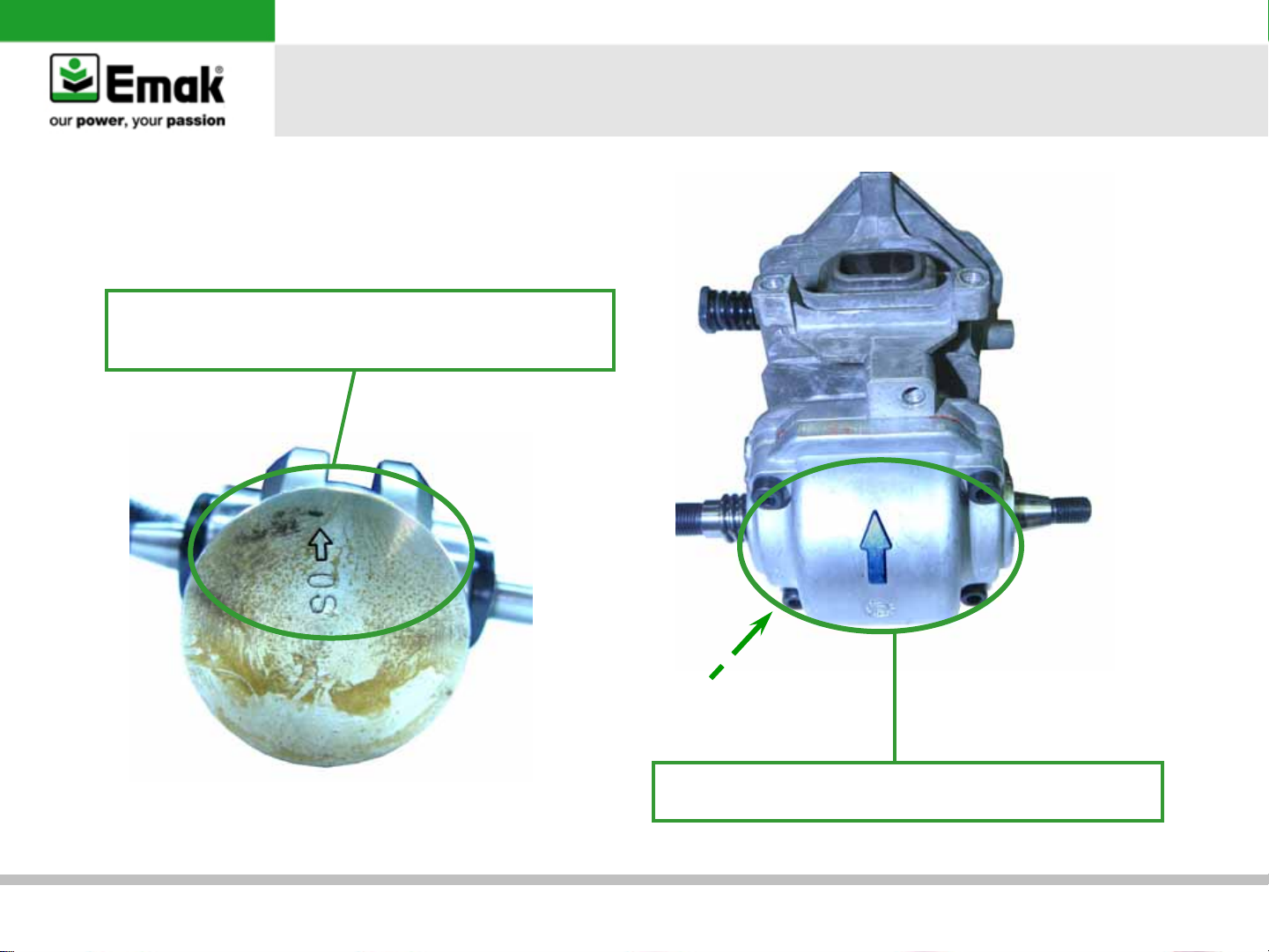
c) Cylinder and piston assembly
Warning:
The arrow on the top of the cylinder points towards
the exhaust port.
General failures’ analysis
Tightening torque cylinder - screws
0,6 Kgm (52,08 in lb) + Loctite 243
The arrow must point towards the exhaust.
GS35 – GS350 – MT350 – MT3500 chainsaws
Warning:
Page 8
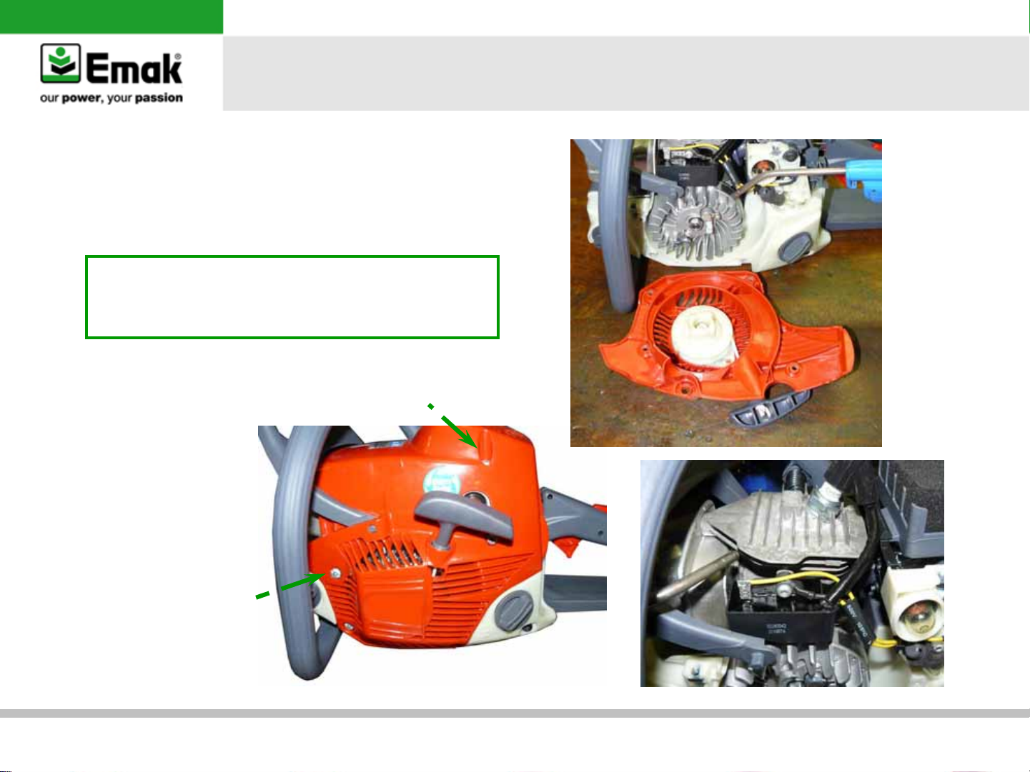
d) Cooling system cleaning
Dismount the cylinder's cover. Blow, with
compressed air, cylinder fins, starter case and
flywheel
Important:
• Clean weekly the cooling system, more
frequently in heavy duty work conditions
• Use Loctite 243 to tighten plastic component
Tightening toque cover-basement
0,4 kgm (34,72 in lb) + Loctite 243
General failures’ analysis
Tightening torque
Cover
0,4 kgm (34,72 in lb)
+ Loctite 243
GS35 – GS350 – MT350 – MT3500 chainsaws
Page 9
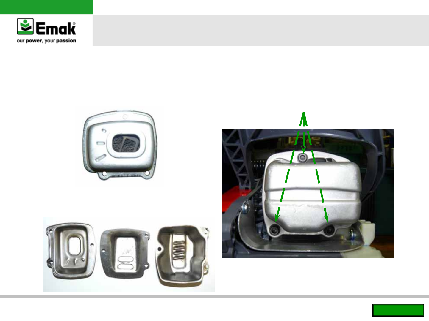
e) Muffler inspection
Catalytic muffler
Verify the conditions of the muffler (dirt / oily)
change if necessary
Non-catalytic muffler
If the muffler is blocked or damaged, clean or replace it
General failures’ analysis
Tightening torque cover muffler-muffler
0,6 kgm (53,10 in lb) + Loctite 243
GS35 – GS350 – MT350 – MT3500 chainsaws
Back to index
Page 10
2) Fuel system
a) Fuel and fuel filter inspection
b) Fuel system test
c) Tank breather inspection
d) Engine seal test
e) Manifold inspection
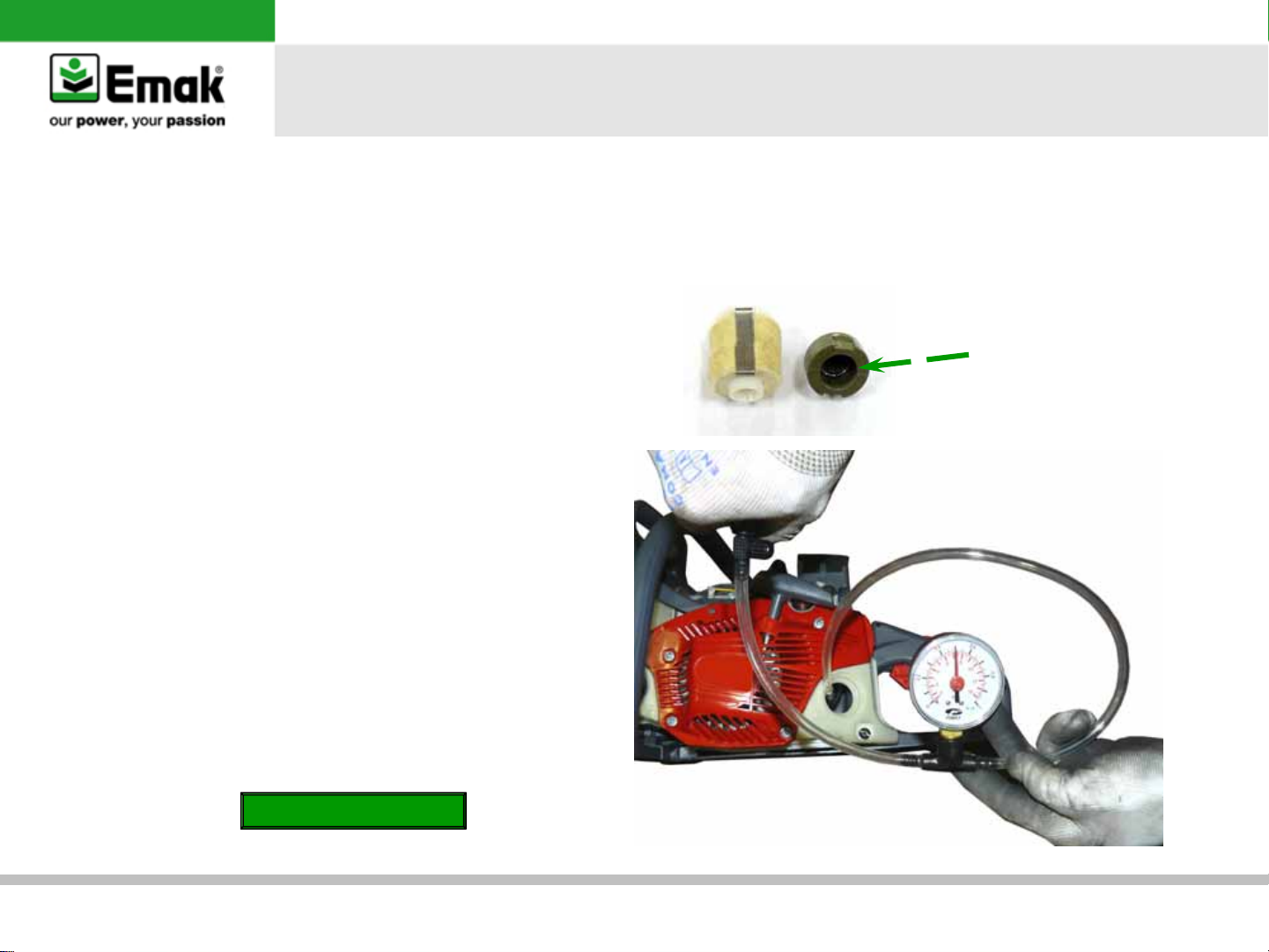
a) Fuel and fuel filter inspection
•
Verify fuel quality odor
•
Dismount and check periodically the fuel filter
and the sintered internal filter. In case of dirt or
oxidation, replace it
General failures’ analysis
Sintered
internal
filter
b) Fuel system test
•
Apply the pressure gauge at the fuel line. Check
any possible leakage at 0,5 bar
•
If the pressure is not stable, it may indicate
worn fuel system or loose at the carburetor
parts
Go to
Carburetor inspection
GS35 – GS350 – MT350 – MT3500 chainsaws
Page 11
General failures’ analysis
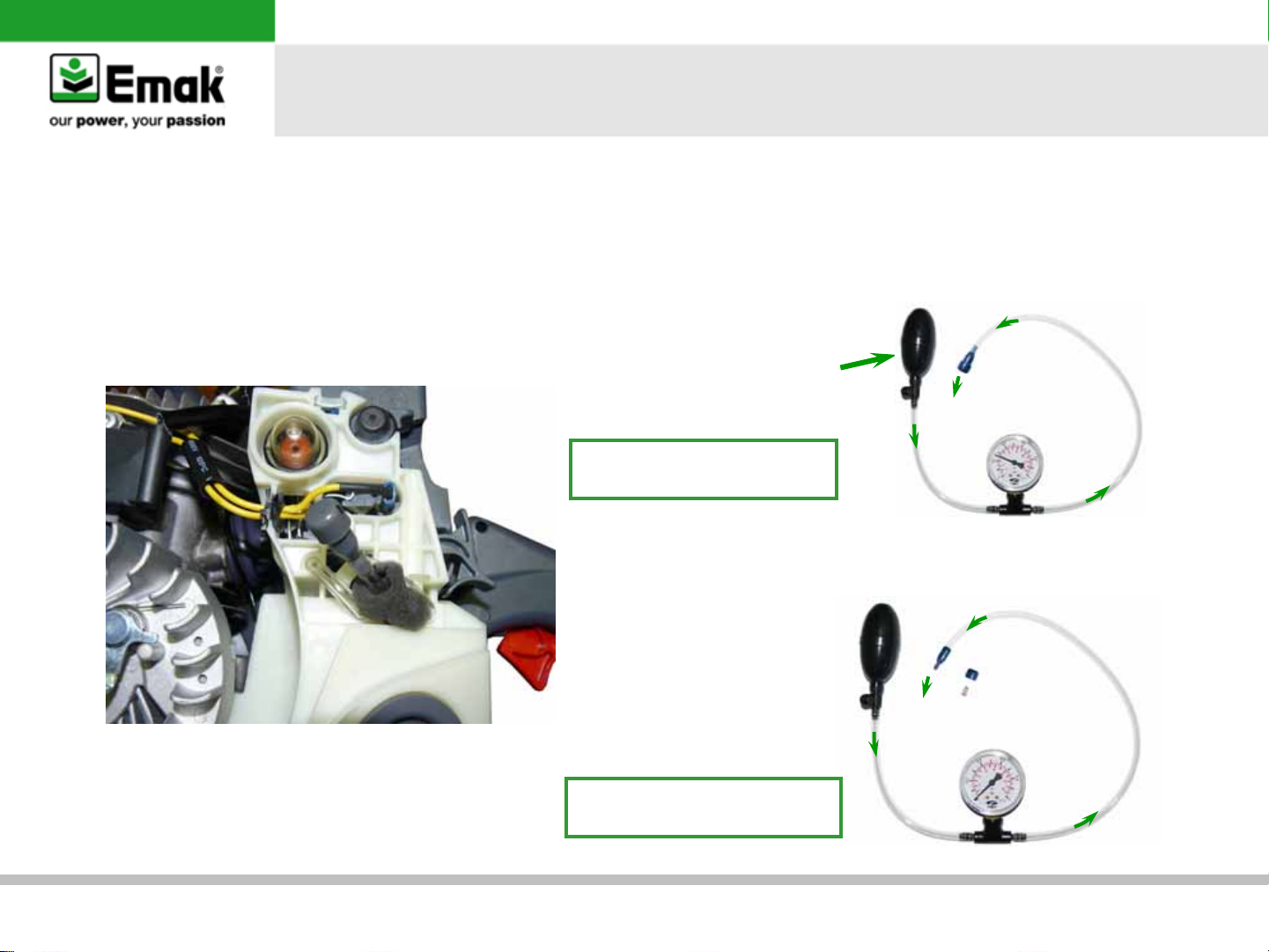
c) Tank breather inspection
•
Dismount the breather and check the components
•
Apply the pressure gauge (I), supplied with Emak tool kit, at the breather valve and verify the correct
working in both ways. Replace or clean if necessary
I
p/n 1043900
Breather sealing test:
0,2 – 0,3 bar
Breathing system test:
0,00 bar
GS35 – GS350 – MT350 – MT3500 chainsaws
Page 12

d) Engine seal test
•
Remove the parts as per the photo. Close off
the inlet port with the correct flange from the
tool kit (I and II)
General failures’ analysis
•
Close the exhaust port by putting the flange
between the muffler and cylinder III (flange in
tool kit). Refit the muffle with the 3 screws M5x25
III
p/n 001000018
II
p/n 094500388A
GS35 – GS350 – MT350 – MT3500 chainsaws
IV
n°3 screws M5x25
Warning:
During the seal test use
only a light torque of
0,4 Kgm (35 in lb)
Page 13

•
Fit the pressure gauge (V) to the inlet and apply 0.5 bar. The pressure should not descend
General failures’ analysis
GS35 – GS350 – MT350 – MT3500 chainsaws
V
p/n 1043900
Page 14

General failures’ analysis
e) Manifold inspection
Check the manifolds for wear. Verify that the manifold’s rubber is not deteriorated or hardened and check
that there are no cuts or holes. Replace if necessary
Make sure the impulse path is
correctly inserted into the
GS35 – GS350 – MT350 – MT3500 chainsaws
Warning!
cylinder hole.
Back to index
Page 15

3) Ignition system
a) Check housing inspection
b) Spark plug inspection
c) Spark arrester test
d) Flywheel-coil air gap inspection
e) Flywheel key way inspection
a) Starter housing inspection
Remove housing. Inspect parts for wear. If
necessary clean or replace
General failures’ analysis
Important: make sure the spring does not wind fully
with the rope fully out
Wind the spring 6
times. Verify that
the spring turns on
½ turn
ø 3,0 x 960 mm
Counterclockwise
turn to release
the spring
Important: grease moving parts
Clockwise turn
to wind the
spring
GS35 – GS350 – MT350 – MT3500 chainsaws
Page 16

General failures’ analysis
b) Spark plug inspection
Remove the spark plug and check the gap
between the electrodes (0,5 – 0,7 mm)
(0,5 – 0,7 mm)
RCJ-7Y
c) Spark test
•
Fit the tester (I) between spark plug and spark
plug cap. Pull the rope and verify the current
•
Replace the spark plug if necessary. Verify that the
spark plug thermal grade and type (resistive – R)
are correct
•
Check that the spark plug pipe is correctly
connected, cables are not damaged and coil works
properly
I
cod. 001000515R
GS35 – GS350 – MT350 – MT3500 chainsaws
Page 17

General failures’ analysis
d) Flywheel-coil air gap inspection
•
Check the air gap using the shim (II-0,3 mm)
•
Adjust if not correct
Tightening torque flywheel-nut
1,9 kgm (168,2 in lb)
e) Flywheel key way inspection
•
•
II
p/n 001000004
Remove flywheel with corrector tool (III)
Inspect key way’s condition and position. If
necessary, replace or adjust
III
p/n 001000782
Tightening torque coil-screws
0,4 kgm (34,72 in lb) + Loctite 243
GS35 – GS350 – MT350 – MT3500 chainsaws
Back to index
Page 18

4) Oil pump, bar and shock absorber
a) Oil tank breather inspection
b) Sprocket inspection
c) Chain brake inspection
d) Oil pump and oil filter inspection
e) Worm gear inspection
f) Shock absorber replacement
g) Lubrication and bar maintenance
a) Oil tank breather inspection
•
Clean with compressed air
•
Verify the quality of the bar and chain oil
General failures’ analysis
I
Warning!
Make sure the O-ring (I) is
seated before inserting the tube
GS35 – GS350 – MT350 – MT3500 chainsaws
Page 19

General failures’ analysis
b) Sprocket/power mate ring inspection
Check the sprocket/power mate ring wear
periodically. Replacement is suggested every
100 hrs or before
c) Chain brake inspection
Check the brake band, the plate and the
protection’s rubber for wear. This must be
changed if the wear limit is less than 0,6 mm
GS35 – GS350 – MT350 – MT3500 chainsaws
Page 20

d) Oil pump and oil filter inspection
•
Use the piston stop (I) in the spark plug hole. Remove the clutch anticlockwise with tool (II)
General failures’ analysis
I
p/n 001000684
Tightening torque clutch
2 Kgm (177,0 in lb) + Loctite 243
II
p/n 3055133
Warning! Make
sure the spacer
washer is fitted (I)
I
GS35 – GS350 – MT350 – MT3500 chainsaws
Page 21

•
Remove the oil pump. Check the pump and worm gear.
•
Inspect the supply hose and filter, clean.
Tightening torque screws oil pump
0,45 kgm (39,83 in lb) + Loctite 243
General failures’ analysis
Warning!
Use a liquid gasket to seal in the
hose to the saw body
GS35 – GS350 – MT350 – MT3500 chainsaws
Page 22

e) Worm gear inspection
If worn or broken replace:
•
Remove with the correct tool from the tool box
(I)
•
Insert the worm gear into the fitting tool
(I) leave about 2 mm sticking out.
•
Fit the worm gear spring on the
crankshaft until the end of the spring
touches the crank seat (Photo 1-2).
•
Screw in the tool until stop (I) to give
the correct pitch to the worm gear.
General failures’ analysis
I
p/n 3055133
Photo 1
GS35 – GS350 – MT350 – MT3500 chainsaws
Photo 2
Page 23

f) Shock absorber replacement
In case of wear or breakage replace the parts
General failures’ analysis
GS35 – GS350 – MT350 – MT3500 chainsaws
Page 24

g) Lubrication and bar maintenance
•
Lubricate the sprocket nose
•
Keep the rail and the lubrication holes cleaned
•
Check the parallelism of the guide bar and for sharp metal edges
•
Turn the bar every 8 hrs to grant uniform wear
Keep
clean
O
S
S
A
GR
General failures’ analysis
GS35 – GS350 – MT350 – MT3500 chainsaws
Back to index
Page 25

5) Tuning
a) Air filters inspection
b) Needle valve inspection
c) Carburetor inspection
d) Suggested tools for carburetion setting
e) Carburetor tuning
Tightening torque
Support air filter-insulator
0,2 Kgm (17,7 in lb)
+ Loctite 243
General failures’ analysis
a) Air filters inspection
•
Sponge air filter (A): clean with
Emak degreaser, rinse with
water and blast dry with
compressed air
•
Cloth air filter (B): shake it and
clean it with a soft brush
•
Replace the filter when damaged
Tightening torque
Support air filter-carburetor
0,4 Kgm (34,72 in lb)
+ Loctite 243
A
GS35 – GS350 – MT350 – MT3500 chainsaws
B
Page 26

General failures’ analysis
b) Needle valve inspection
Check the right position of the valve using a
caliper. Adjust if necessary
Needle
c) Carburetor inspection
Check and clean all components (diaphragm,
needle, filter). Use the repair kit to replace worn
components. If the carburetor is oxidized, replace
it
OK REPLACE
GS35 – GS350 – MT350 – MT3500 chainsaws
Back to fuel system
Page 27

d) Suggested tools for carburetor setting
Special screwdriver (I): for adjustment the jets “L” e “H”
General failures’ analysis
Insert the special
screwdriver (as shown
on the photo) and
adjust the jets
I
p/n 3055130
GS35 – GS350 – MT350 – MT3500 chainsaws
Page 28

General failures’ analysis
e) Carburetor tuning
Correct tuning of the EURO 1 (direttiva 97/68/CE + 2002/88/CE) and EURO 2 (direttiva 97/68/CE + 2002/88/CE
+ 2004/26/CE).
The jets have the following factory registration: L = 1+3/8±1/4 H=1±1/4
When, following a repair or engine overhaul, you are obliged to re-tune the carburetor to its’ original setting
Idling adjustment (L)
1. Start the unit and warm up for 60 seconds. If the engine stop, readjust T screw
2. Close the L jet until the maximum number of rpm is reached (stop rotating the jet before the rpms drop or
the unit stalls);
3. Adjust the T screw until the unit reaches an idle rpm between: 3700 and 4200 RPM
4. Open the jet L until the rpm go from 3700/4200 to 2800/3100 RPM
Maximum adjustment (H)
5. Adjustment of the jet H for wide open throttle operation whit bar (standard 16” - 41 cm) and chain:
10600 RPM with the new motor and 12100 RMP with run-in engine
GS35 – GS350 – MT350 – MT3500 chainsaws
Back to index
Page 29

Tightening torques
(kgm) – (in lb) / lubrication
* = Loctite 243
G = Grease
O = Oil
General failures’ analysis
6) Tightening torques
2 – 177,0
0,4 - 34,72 *
0,4 - 34,72 *
1,9 - 168,2 *
0,25 – 22,13 *
O
0,6 - 52,08 *
GS35 – GS350 – MT350 – MT3500 chainsaws
Page 30

0,25 – 22,13 *
0,25 – 22,13 *
General failures’ analysis
0,6 - 52,08 *
0,2 – 17,7 *
0,4 - 34,72 *
Tightening torques
(kgm) – (in lb) / lubrication
* = Loctite 243
G = Grease
O = Oil
GS35 – GS350 – MT350 – MT3500 chainsaws
Page 31

0,7 – 61,96 *
General failures’ analysis
0,35 –
30,98 *
0,35 –
30,98 *
0,4 - 34,72 *
0,7 – 61,96 *
0,35 –
0,04 – 3,54
0,4 – 34,72 *
Tightening torques
(kgm) – (in lb) / lubrication
0,35 – 30,98 *
30,98 *
* = Loctite 243
G = Grease
O = Oil
GS35 – GS350 – MT350 – MT3500 chainsaws
Page 32

0,45 - 39,83 *
General failures’ analysis
Tightening torque
(kgm) – (in lb) / lubrication
* = Loctite 243
G = Grease
O = Oil
0,5 – 44,25 *
1,5 – 132,76
2 - 177,0 *
G
GS35 – GS350 – MT350 – MT3500 chainsaws
0,25 - 22,13 *
Back to index
Page 33

General failures’ analysis
7) Trouble shooting: ENGINE DOES NOT START
Symptoms Causes Remedies Go to
1. The engine does not
turn over
2. There is no
compression
3. No spark
4. Fuel does not reach
the carburetor, the
machine stops after 5
minutes
5. Wrong carburetion
setting or erratic
throttle response
1.a Starter assy defect or
broken starter rope
1.b Internal damage
2.a Spark plug looses
2.b Piston ring, cylinder and
piston worn
3.a Ignition switch is in “OFF”
position
3.b Ignition system defected
3.c Broken spark plug or
wrong type
4.a Fuel filter or breather
blocked
4.b Fuel system is leaking air
4.c Wet spark plug, flooded
cylinder
5.a Air filter dirty
5.b Wrong L and H setting
5.c Carburetor problems
5.d Manifold problems
1.a Check starter assy or starter rope
replacement
1.b Check thermal group and replace
worn components
2.a Tighten spark plug. Compression
test
2.b Replace worn or damaged parts.
Compression test
3.a Switch “ON” and restart
3.b Inspect and/or replace
3.c Replace the spark plug
4.a Clean or replace
4.b Tightness test on fuel system
4.c Carburetor inspection (point 5.c).
Take off spark plug, rotate the engine,
blow inside cylinder passing through
spark plug hole, dry the spark plug
and restart
5.a Clean or replace
5.b Adjust the carburetion according
the above
5.c Carburetor inspection
5.d Manifold tightness
Section 3
Section 1
Section 1
Section 1
Section 3
Section 3
Section 2
Section 2
Section 5
Section 5
Section 5
Section 5
Section 2
GS35 – GS350 – MT350 – MT3500 chainsaws
Page 34

General failures’ analysis
Trouble shooting: LOW PERFORMANCE
Symptoms Causes Remedies Go to
1. Engine
overheating
2. Engine
performance is
not stable
1.a Carburetor mixture too lean
1.b Air leaking in the engine or in
fuel system
1.c Wrong oil-fuel ratio
1.d Fan, starter housing, cylinder
fins dirty or damage
1.e Carbon deposit on piston
2.a Dirty air filter
2.b Loose spark plug or damaged
2.c Water in the fuel
2.d Seizure
2.e Faulty carburetor or diaphragm
1.a Set the carburetor
1.b Find air leaking and eliminate it
1.c Replace with fresh fuel and right
oil ratio
1.d Clean or replace it
1.e Eliminate deposit
2.a Clean or replace
2.b Tighten or replace
2.c Clean the carburetor and replace
fuel
2.d Replace the components
2.e Check and replace
Section 5
Section 1
Section 2
Section 1
Section 1
Section 5
Section 3
Section 5
Section 1
Section 5
GS35 – GS350 – MT350 – MT3500 chainsaws
Page 35

General failures’ analysis
Trouble shooting: ADDITIONAL PROBLEMS
Symptoms Causes Remedies Go to
1. The chain does not
work correctly or does not
rotate
1.a Bended or worn bar
1.b Lubrication system blocked
1.c Worn sprocket
1.d The chain is not sharp
1.e Chain to tight
1.a Replace or maintain
1.b Clean or replace
1.c Replace sprocket
1.d Sharpen the chain
1.e Correct tension/assembly
bar and chain
Section 4
Section 4
Section 4
Owner’s
manual
Owner’s
manual
GS35 – GS350 – MT350 – MT3500 chainsaws
Back to index
 Loading...