

EMAK EP 90, EP 100 Operator's Manual

S.P.A.
R
Operator’s Manual GB
S.P.A.
R
G
F
D
E
Verso rotazione
4MM
BA
C
H
Manuale d’istruzioni I
Manuel d’instructions F
Bedienungsanleitung D
Manual de instruccione E
Gebruikershandleiding NL
Ägarhandbok S
Brugehåndbog DK
Omistajanskäsikirja FIN
Eierens Håndbok N
Manual de Instruções P
GR
Haszanálati útmutató H
EP 90 EP 100
B
G
F
D
E
Verso rotazione
4MM
BA
C
H
C
G
F
D
E
Verso rotazione
4MM
BA
C
H
D
C
A
D
F
B
D
C
EP90
MODEL
A
B
EP100
MODEL
E

GB
I
Due to a constant product improvement proframme, the factory reserves the
right to modify thchnical details mentioned in this manual without prior notice.
La casa costruttrice si riserva la possibilità di variare caratteristiche e dati del
presente manuale in qualunque momento e senza preavviso.
F
D
E
NL
S
DK
FIN
La Màison se réserve la possibilité de chenger des caractéristiques et des
données de ce manuel à n’importe quel moment et sans préavis.
Im Sinne des Fortschritts behält sich der Hertseller des Recht vor, technische
Änderungen ohne vorherigen HinWeis durchzuführen.
La firma productora se reserva la posibilitad de cambiar las caracteristicas y
datos del presente manual en cualquier momento y sin previo aviso.
Door konstante produkt ontwikkeling behoud de fabrikant zich het recht voor
om rechnische specificaties zoals vermeld in deze handleiding te varanderen
zonder biervan vooraf bericht te geven.
Tilverkaren reserverar sig rätten att ändra fakta och uppgifter ur handboken
utan förvarning.
Producenten forbeholder sig ret til ændringer, hvad angår karakteristika og
data i nærværende instruktion, når som helst og uden varsel.
Jatkuvan tuotten parannusohjelman tähden valmistaja pidättää oikeunden
vaihtaa ilman ennakkovaroitusta tässä ohjekirjasessa mainittuja teknisiä
yksityskohtia.
N
P
GR
H
Produsenten forbeholder seg all rett og mulighet til å forandre tekniske
detaljer i denne manualen uten forhåndsvarsel.
A casa productora se reserva a possibilitade de variar caracteristicas e dados
do presente manual em qualquer momento e sen aviso prévio.
Folyamatos gyártmány felùjitási müsorunk következtében, a gyártó cég fenn
tartja a jogát ebben a Használati leirt müszaki adatok elözetes értesités nélküli változtatására.
-

THIS PRODUCT MEETS THE SAFETY STANDARD REQUIREMENT OF THE
EUROPEAN MACHINERY DIRECTIVE
RY WEIGHT (kg)(NO BAR AND CHAIN
D
CHAIN PITCH .........................................................................................................................................
CHAIN GAUGE (mm) ............................................................................................................................
BAR LENGTHS (cm) ..............................................................................................................................
No. OF SPROCKET TEETH ..............................................................................................................
SPECIFICATIONS
OIL TANK CAPACITI (cm3) .
.................................................................................................................
...................................................................................
GB
0.75
3/8’’
1.1
25
6
184
QUESTO PRODOTTO È CONFORME ALLADIRETTIVAEUROPEA SULLA
SICUREZZA DELLE MACCHINE
PESO ASECCO (Kg) (SENZA BARRAE CATENA) .............................................................
PASSO CATENA ......................................................................................................................................
SPESSORE CATENA(mm) ...............................................................................................................
LUNGHEZZA BARRA(cm) .
DATI TECNICI
No. DENTI DEL PIGNONE .................................................................................................................
CAPACITÀ SERBATOIO OLIO (cm3) .............................................................................................
CE PRODUIT EST CONFORME À LA NORME EUROPÉENNE POUR LA
SÉCURITÉ DES MACHINES
POIDS A VIDE (Kg) (SANS BARRE NI CHAÎNE) ..................................................................
PAS DE LACHAÎNE ...............................................................................................................................
JAUGE (mm) ..............................................................................................................................................
LONGUEUR DE GUIDE (cm) ...........................................................................................................
TECHNIQUES
NOMBRE DES DENTS DE PIGNONS ........................................................................................
CARACTÉRISTIQUES
CAPACITÉ DU RÉSERVOIR HUILE (cm3) ................................................................................
DIESE PRODUKT ENTSPRICHT DEN EUROPÄISCHEN BESTIMMUNGEN
FÜR MASCHINENSICHERHEIT
GEWICHT MOTOR (Kg) (OHNE SCHWERT UND KETTE) .............................................
KETTENTEILUNG .................................................................................................................................
TREIBGLIEDSTÄRKE (mm) ..............................................................................................................
SCHWERTLÄNGE (cm) .......................................................................................................................
TECHNISCHE
ANZAHL ZAEHNE DES RITZELS ...................................................................................................
BESCHREIBUNG
ÖLTANK-INHALT (cm3) .........................................................................................................................
ESTE PRODUCTO ES CONFORME ALA NORMA EUROPEADE
SEGURIDAD DE LAS MÁQUINAS
PESO EN VACIO (Kg) (SIN BARRA NY CADENA) ..............................................................
PASO DE LACADENA ........................................................................................................................
ESPESOR DE LA CADENA(mm) ...................................................................................................
TÉCNICAS
MEDIDA DE LA BARRA (cm) .........................................................................................................
NÚMERO DIENTES DEL PIÑÕN ....................................................................................................
CARACTERÍSTICAS
CAPACIDAD DELDEPÓSITO DE ACEITE (cm3) ....................................................................
...............................................................................................................
I
0.75
3/8’’
1.1
25
6
184
F
0.75
3/8’’
1.1
25
6
184
D
0.75
3/8’’
1.1
25
6
184
E
0.75
3/8’’
1.1
25
6
184
DIT PRODUKT IS IN OVEREENSTEMMING MED DE EUROPESE
VEILIGHEIDSREGELING VOOR DE MACHINE
LEDIG GEWICHT (Kg) (ZONDER ZWAARD EN KETTING) .............................................
KETTING STEEK ...................................................................................................................................
AANDRIJFSCHAEL
DIKTE
ZWAARDLENGTES (cm) ....................................................................................................................
GEGEVENS
TECHNISCHE
AANDRIJFTANWIEL(STANDAARD) TANDEN ........................................................................
INHOUD OLIETANK (cm3) ..................................................................................................................
(mm)
....................................................................................................
NL
0.75
3/8’’
1.1
25
6
184

PRODUKTEN MOTSVARAR EUROPA RÅDETS KRAI PÄ SÄKERHET
ARRVIKT (Kg) (EXCL KEDJA OCH SVÄRD)
T
KEDJEDELNING ....................................................................................................................................
KEDJETJOCKLEK (mm) ......................................................................................................................
SVÅRDLÅNGD (cm) ..............................................................................................................................
AVBRYTNA TÄNDER ............................................................................................................................
TEKNISKA DATATEKNISKE DATA
OLJEBEHÅLLARENS KAPACITET (cm3) ...................................................................................
DETTE PRODUKT ER REMSTILLET I HENOLD TIL DE EUROPÆSKE
BESTEMMELSER VEDRØRENDE MASKINERS SIKKERHED
NETTO VÆGT (Kg) (UDEN SVÆRD OG KÆDE) .................................................................
KÆDETRÆK .............................................................................................................................................
KÆDETYKKELSE (mm) ......................................................................................................................
SVÆRDLÆNGDE (cm) ........................................................................................................................
ANTALTÆNDER PÅ KÆNDHJUL .................................................................................................
OLIETANKENS KAPACITET (cm3) .................................................................................................
TÄMÄ TUOTE VASTAA EUROOPAN DIREKTIIVIÄKONEIDEN
TURVALLISUUDESTA
DOT
MOOTTORIN PAINO (Kg)(ILMAN TERÄLEVYÄ JA KETJUA) .........................................
TERÄN JAKO ...........................................................................................................................................
KETJUN PAKSUUS (mm) ...................................................................................................................
TERÄLEVYN PITUUS (cm) ................................................................................................................
HAMMASRATTAAN TERIEN LUKUMÄÄRÄ ..............................................................................
TEKNISET TIE
ÖLJYSÄILIÖN TILAVUUS (cm3) .......................................................................................................
DETTE PRODUKTET ER I OVERENSSTEMMELSE MED DE EUROPEISKE
NORMER FOR IKKERHET PAAMASKINER
NETTO VEKT (Kg) (UTEN SVERD OG KJEDE) .....................................................................
DELING ........................................................................................................................................................
DRIVLENKETYKKELSE (mm) ..........................................................................................................
SVERDLENGDE (cm) ...........................................................................................................................
ANTAAL TENNER PÅ TANNHJULET ...........................................................................................
TEKNISKE DATA
OLJETANKKAPASITET (cm3) ...........................................................................................................
ESTE PRODUTO ESTÁ EM COMFORMIDADE COM ADIRETRIZ EUROPÉIA
SOBRE A SEGURANÇADAS MAQUINAS
PESO EM SECO (Kg) (SIN BARRA E CORRENTE) ............................................................
PASSO CORRENTE ..............................................................................................................................
ESPESSURA CORRENTE (mm) ....................................................................................................
COMPRIMENTO BARRA (cm) .........................................................................................................
TECNICAS
No DE DENTES DO PINHON ...........................................................................................................
CARACTÉRISTICAS
CAPACIDADE DEPÓSITO ÓLEO (cm3) .......................................................................................
.........................................................................
S
0.75
3/8’’
1.1
25
6
184
DK
0.75
3/8’’
1.1
25
6
184
FIN
0.75
3/8’’
1.1
25
6
184
N
0.75
3/8’’
1.1
25
6
184
P
0.75
3/8’’
1.1
25
6
184
....................................................................................................................
................................................................................................................................
TEXNIKA
XAPAKTHPI∑TIKA
EZ A GYÁRTMÁNY MEGFELEL AZ EUROPAI GÉP BIZTONSÁGI
ELÓIRÁSNAK
MOTOR SÚLYA (Kg) (LÁNC ÉS VEZETÓLAP NÉLKÜL) ...................................................
LÁNCOSZTÁS ..........................................................................................................................................
LÁNCSZEMEK ERÓSSÉGÉ (mm) .................................................................................................
“
VEZETÓLAP
MUSZAKI
FOGASKERÉK FOGAINAK SZAMA ..............................................................................................
PARAMÉTEREK
OLAJT
ANKÚR
MÉRET
TARTALOM (cm
................................................................................................................
........................................................................................................................
(cm)
.................................................................................................................
...............................................................................................
3
) .....................................................................................................
...............................................................
...................................................................
.........................................................................
GR
0.75
3/8’’
1.1
25
6
184
H
0.75
3/8’’
1.1
25
6
184
GB
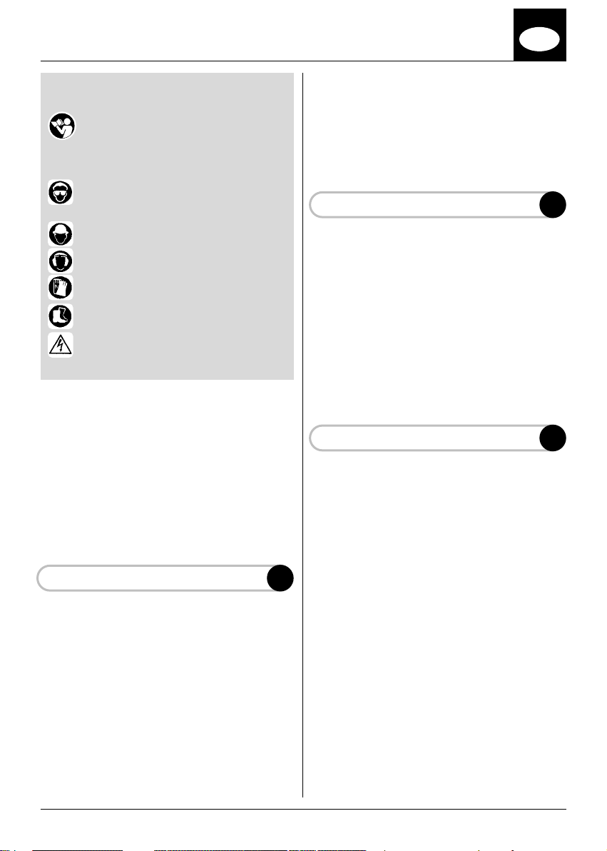
EXPLANATION OF SYMBOLS
Read this manual carefully.
Protective clothing required.
1 - Protective glasses or alternatively
an approved protective visor
2 - Approved protective helmet
3 - Approved ear protectors
4 - Approved gloves
5 - Approved safety boots
6 - Respect the warning given with
the distance of electrical lines
INDEX
A – GENERAL INFORMATION
B – DESCRIPTION OF THE PARTS
C – SAFETY NORMS
D – ASSEMBLY OF BAR AND CHAIN
E – INSTALLATION OF PRUNER
F – STARTING AND USE
G – MAINTENANCE
H - SHARPENING THE CHAIN
In this last case it is necessary to avoid allowing
the blade to come into contact with stones or
earth.
In pruning high branches, take up a solid position
on the ground and avoid standing underneath the
branch to be cut.
DO NOT USE A LADDER AND DO NOT CLIMB
INTO TREES.
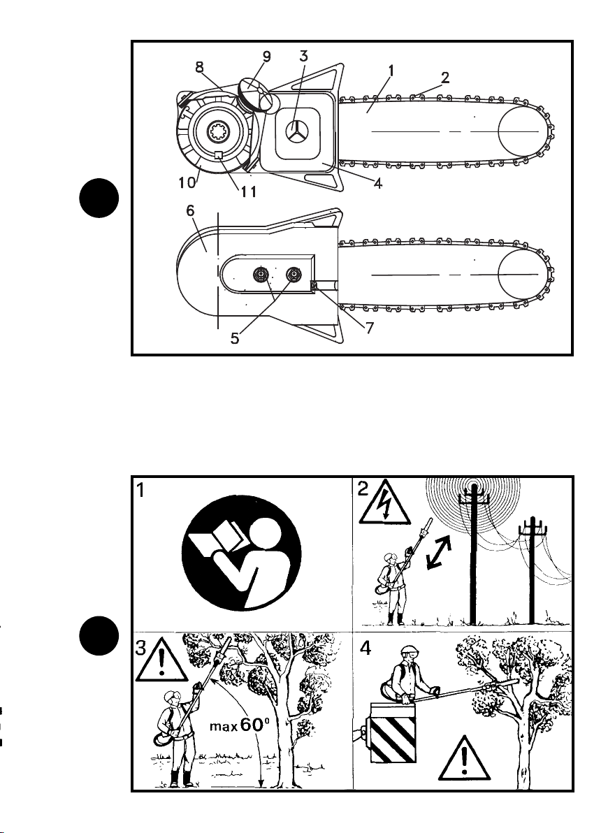
DESCRIPTION OF THE PARTS
1 - BAR
2 - CHAIN
3 - OIL CAP
4 - OIL TANK
5 - NUTS FOR FIXING THE BAR
6 - CHAIN COVER
7 - SCREW FOR ADJUSTING THE CHAIN
8 - BELL-SHAPED BRACKET
9 - KNOB FOR BLOCKING BEVEL GEAR
10 - INTERFACE ADAPTOR
11 - KEY OF REFERENCE FOR THE BEVEL
GEAR
SAFETY NORMS
The EP90 / EP100 pruner can only be installed
on EMAK machines.
Always keep the motor of the strimmer turned off
while preparing the work area.
Apply the bar cover when transporting the machine.
B
C
GENERAL INFORMATION
The pruning module EMAK EP90 / EP100 is an
accessory that can be installed on a strimmer in
place of the disk or string.
The installation operation on the machine is
carried out with the sole use of one’s hands:
or other instruments are not required.
The areas that can be reached for pruning with
this accessory are of the most varied. The
operator should take up the most suitable
position and carry out most of the work without
moving from that position.
With this accessory it is possible to cut down
bushes to ground level while maintaining the
same standard position as that used for
strimming.
A
keys
1 - The information given should be used with
care.
2 - Do not do any cutting operations near high
tension lines as there is a danger of electric
shock.
DO NOT OPERATE WITHIN 15 METRES
OF ELECTRIC LINE.
Do not operate within 15 metres of persons
or animals, as the field of action of the pruner
could be dangerous to them.
3 - Do not carry out cutting operations at an
angle that exceeds 60
4 - Do not use ladders or unsteady positions.
Keep the work area clean to make it easy to
leave the area if necessary
climb trees with the pruner. For high-level
operations, a cabin with an hydraulic lifter is
required.
to the ground.
°
. It is prohibited to
3
GB
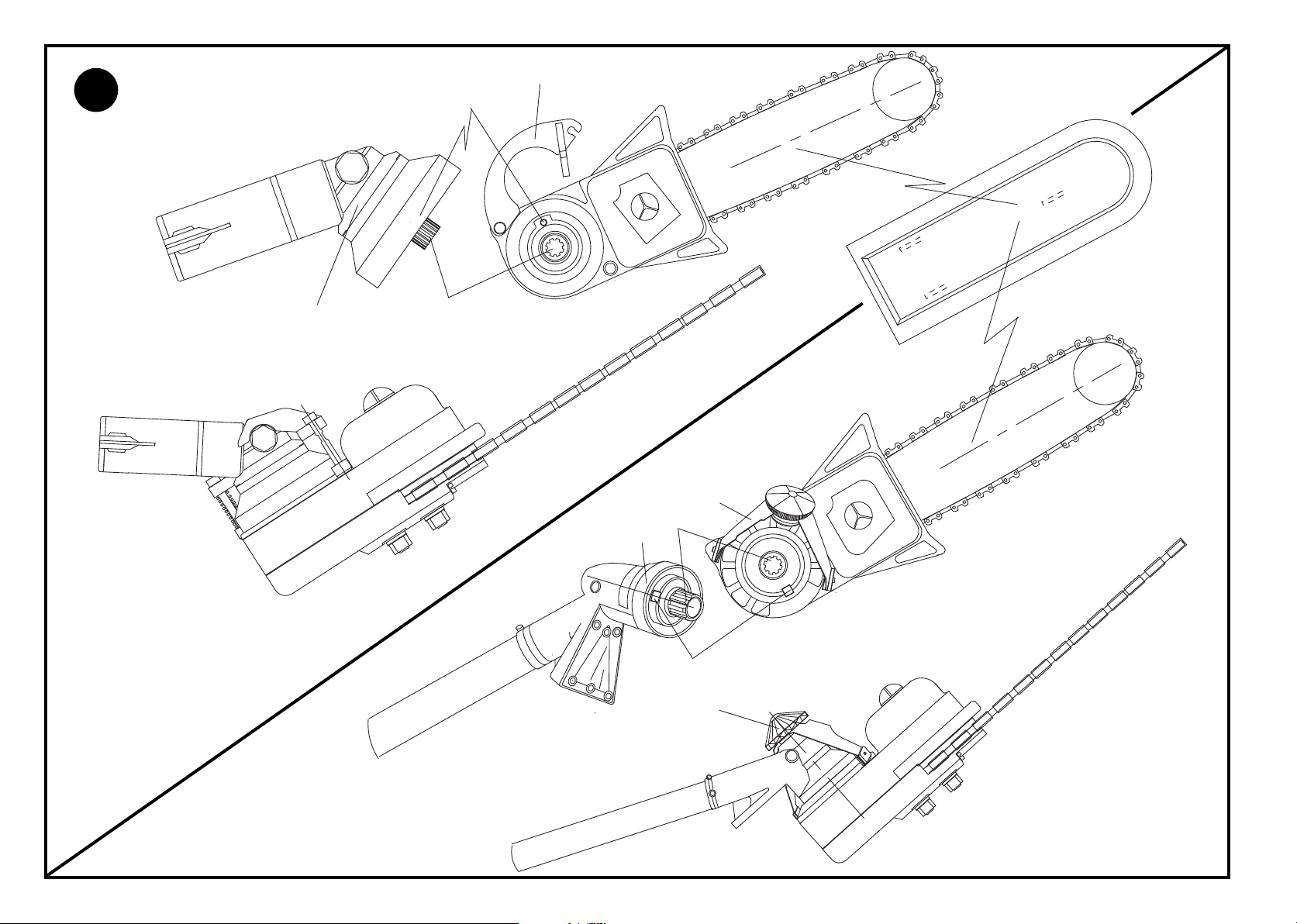
ASSEMBLY BAR AND CHAIN
The EP90 / EP100 pruner comes complete with a
bar and chain assembled and adjusted in the factory.
For replacing the bar and chain, or after resharpening the chain, follow this procedure:
1 - Loosen the two self-blocking nuts (A) and
remove the cover (B)
Set the chain in the groove (C) of the blade and
2 -
at the same time on the driving sprocket (D);
now looking at the blade and chain together
check that the chain is set with the cutting
edges turned in a clockwise direction (E).
3 - Fix the cover where you previously set the
chain stretcher in a drawn back position (F).
4 - Make the chain stretcher pin coincide with the
hole (G) on the blade, by working on the adjustment screw (H).
5 - Tighten the nuts (A) on the cover with a slight
twist. Work on the chain stretching screw (H)
by turning it anti-clockwise; check the tension
of the chain so that by raising it the inside of
the chain is just visible for about 4 mm.
A correct adjustment has been made when
the chain runs freely.
Now tighten the nuts (A) as much as possible.
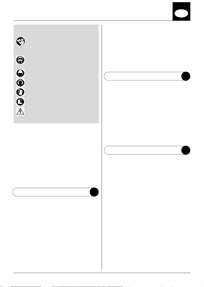
INSTALLATION OF THE PRUNER
Bracket (A) open; unscrew the knurled knob;
insert E
1 - Set the bell-shaped the bevel gear (B) on the
adaptor to make the reference pin (C)
coincide with the slot on the bevel gear and
the toothed pin with the central joint (D).
2 - Bring the bell-shaped bracket with the
rubber-carrying disk over the head of the
bevel gear (F). Tighten the knurled knob by
hand.
STARTING AND MAINTENANCE
1 - The pruner has a pump for lubricating the
chain which guarantees the correct quantity
during operation.
The amount that the pump delivers has been
dosed to reduce the impact with the environment to a minimum, and at the same time assure the correct quantity for lubricating the chain.
D
E
F
2 - For best results use average viscosity oils, do
not use regenerated oil as it could damage
the pump.
3 - When starting the strimmer check that the
chain does not touch anything, even the
ground. For starting instructions refer to the
instructions provided with the machine.
4 - Advice for a correct cut. Remember not to
stand below the branch to be cut. In order to
avoid the decortication that could occur
towards the end of the cutting operation,
before starting make a few incisions in the
under part of the branch. If the branch is very
big more than one cutting operation can be
carried out to lighten the branch and better
control the job. If necessary repeat the cut.
PERIODICAL MAINTENANCE
Maintenance must be carried out while the
engine is turned off. Check that the switch of the
machine is in the “OFF” position.
Check the tension of the chain by following the
indications of point “D”
A new chain may need more frequent adjusting.
Adjustments can be made with more accuracy by
removing the pruner from the machine; this
makes it possible to carry out the maintenance of
the pruner in the workshop.
SHARPENING THE CHAIN
The chain can be sharpened while the pruner is
installed or when it has been removed from the
machine.
The removal or sharpening operation must be
carried out with the engine turned off and the
switch in the “OFF” position.
The sharpening operation must be carried out
with a disc file, 4mm in diameter (5/32”), for the
chain model N4C-BL-38E, which is installed on
your pruner. Get a blade guide with which to
hold the chain and alternatively sharpen on the
right and left tooth with an angle of 55°/60°. If you
do not have a blade guide, stretch the chain on
the blade using the adjusting screw so as to keep
the chain stable, and sharpen. Proceed with a flat
file to reduce the height of the limiting device
which must be inferior by 0.6 to 0.7 from the cutting plane. Check the operation with a calibre.
G
H
4
SPIEGAZIONE SIMBOLI
Leggere attentamente questo manuale
Abbigliamento di sicurezza richiesto:
I
lama vada a contatto con sassi o terra.
Nella potatura in alto assumere una posizione
sicura a terra, ed evitare di sostare al di sotto del
ramo da tagliare.
NON UTILIZZARE SCALE E NON ARRAMPICARSI SUGLI ALBERI
1 - Occhiali di protezione in alternativa
visiera protettiva omologata
2 - Casco protettivo omologato
3 - Cuffie di protezione omologate
4 - Guanti omologati
5 - Stivali di sicurezza omologati
6 - Rispettare l’avvertenza richiesta
nelle vicinanze delle lineee elettriche
INDICE
A- INFORMAZIONI GENERALI
B- DESCRIZIONE DEI COMPONENTI
C- NORME DI SICUREZZA
D- MONTAGGIO BARRAE CATENA
E- INSTALLAZIONE POTATORE
F- AVVIAMENTO ED USO
G- MANUTENZIONE
H. AFFILATURA CATENA
INFORMAZIONI GENERALI
Il modulo potatore EMAK EP90 / EP100 è un
accessorio che si installa sul decespugliatore al
posto del disco o filo.
L’operazione di installazione sulla macchina si
realizza con il solo uso delle mani,
necessarie chiavi oppure altri utensili.
Le zone di potatura che si raggiungono con questo accessorio sono le più svariate, sta all’operatore impostare la posizione più adeguata ed ese
guire gran parte del lavoro senza spostarsi.
Questo accessorio consente di tagliare arbusti al
suolo mantenendo la stessa posizione standard
che si assume nell’uso del decespugliatore.
In questo ultimo caso è necessario evitare che la
A
non sono
DESCRIZIONE DEI COMPONENTI
1 - BARRA
2 - CATENA
3 - TAPPO OLIO
4 - SERBATOIO OLIO
5 - DADI FISSAGGIO BARRA
6 - COPERCHIO CATENA
7 - VITE REGOLAZIONE CATENA
8 - STAFFAA CAMPANA
9 - MANOPOLA BLOCCO COPPIACONICA
10 - ADATTATORE DI INTERFACCIA
11 -CHIAVETTA DI RIFERIMENTO COPPIA
CONICA
NORME DI SICUREZZA
Il potatore EP90 / EP100 può essere installato
solo su macchine EMAK
Durante la fasi di approntamento l’area di lavoro
spegnere sempre il motore del decespugliatore.
Applicare il copri barra nelle fasi di trasporto della
macchina.
1 - E’ necessario utilizare con attenzione le infor-
mazioni riportate.
2 - Non effettuate operazioni di taglio nelle vici-
nanze di linee ad alta tensione pericolo di
scossa.
NON OPERATE A DISTANZE INFERIORI A
15 METRI DALLE LINEE ELETTRICHE
Non operate ad una distanza inferiore a 15
metri, da animali o persone, il campo d’azione del potatore può mettere in pericolo
le stesse.
3 - Non effettuare operazioni di taglio con angolo
-
superiore a 60° con il suolo.
4 - Non utilizzare scale o posizioni incerte, tene-
te pulita la zona di lavoro per facilitare un
eventuale allontanamento. E’ vietato salire
sugli alberi con il potatore, è consentito solo
su cabina con sollevamento idraulico.
B
C
5
I
MONTAGGIO BARRA E CATENA
Il potatore EP90 / EP100 viene fornito con barra
e catena installati e regolati in fabbrica.
Per le operazioni di sostituzione della barra e
catena, oppure dopo la riaffilature della catena,
procedere nel seguente modo:
1 - Svitare i due dadi autobloccanti (A) e rimuo-
vere il coperchio. (B)
2 - Alloggiare la catena nella gola (C) della lama
e contemporaneamente sul rocchetto (D) di
trasmissione, guardando ora l’assieme lama
e catena assicurarsi che la catena sia con i
taglienti rivolti nel verso orario. (E)
3 - Posizionare il coperchio dove in precedenza
avete portato in posizione arretrata il nottolino tendi catena. (F)
4 - Far coincidere il perno tendi catena con il foro
(G) sulla lama, operando sulla vite di regolazione. (H)
5 - Avvitare con leggero precarico i dadi (A) sul
coperchio. Agire sulla vite tendi catena (H)
ruotando in senso orario, verificare la tensione della catena in modo che sollevando la
stessa sia appena visibile l’interno della
maglia per circa 4mm.
La giusta regolazione è eseguita quando la
catena scorre liberamente.
Serrare a fondo i dadi. (A)
INSTALLAZIONE DEL POTATORE
1 - Posizionare aperta la staffa a campana(A)
svitare il pomello godronato, inserire la coppia conica, (B) sull’adattatore e far coincidere
la spina (C) di riferimento con la cava sulla
coppia conica ed il perno dentato sul giuntino
centrale.(D)
2 - Portare la staffa a campana con il piattello
porta gomma sopra la testa della coppia
conica.(F) Avvitare il pomello godronato con
la forza della mano.
AVVIAMENTO ED USO
1 - Il potatore è munito di pompa di lubrificazione
della catena che assicura la quantità necessaria alla catena durante il moto.
La quantità che la pompa eroga è stata dosa
ta per ridurre a minimo l’impatto con l’ambiente, ed assicurare nello stesso tempo la quan
tità necessaria alla lubrificazione della catena
D
E
F
2 - Per un corretto funzionamento usare olii di
media viscosità, non usare olio di recupero,
previo danneggiamento della pompa.
3 - Durante l’avviamento del decespugliatore
assicurarsi che la catena non tocchi nessun
oggetto compreso il terreno. Per le istruzioni
di avvio riferirsi alle istruzioni in dotazione
della macchina.
4-Consigli per una corretta esecuzione del
taglio. Si rammenta di non sostare al di sotto
del ramo da tagliare. Per evitare la scortecciatura che si può verificare verso la fine dell’operazione di taglio, eseguire, prima, nel lato
inferiore del ramo stesso un paio di intagli.Se
il ramo è abbastanza grande si possono effettuare più di un operazione di taglio per alleggerirlo e gestire meglio il lavoro. Se necessario ripassare il taglio.
MANUTENZIONE PERIODICA
Le manutenzioni vanno effettuate con il motore
spento. Assicurarsi che l’interruttore della macchina sia in posizione “OFF”
Regolare la tenzione della catena seguendo le
indicazioni del punto. “D”
Una catena nuova può richiedere una regolazione più frequente. Le regolazioni possono essere
eseguite con più accortezza rimuovendo il potatore dalla macchina, ciò consente di mantenere il
potatore in laboratorio.
AFFILATURA CATENA
L’affilatura della catena è una operazione che si
può eseguire con il potatore installato oppure
rimosso dalla macchina.
Eseguire le operazioni di rimozione oppure di affilatura con macchina spenta, ed interruttore in
posizione “OFF”
L’affilatura deve essere eseguita con una lima a
tondino, di diametro 4mm (5/32”), per la catena
mod. N4C-BL-38E, che è installata sul vostro
potatore. Procurarsi un guida lame con il quale
impegnare la catena ed eseguire alternativamente nel dente destro e sinistro l’affilatura con un
angolo tra i 55°/60°. In mancanza di un guida
lame, tendere la catena sulla lama usando la vite
di regolazione in modo da tenere stabile la cate
-
na, ed eseguire l’affilatura. Procedere con una
lima piana per ridurre l’altezza del limitatore che
-
deve risultare inferiore di 0.6 a 0.7 dal piano del
tagliente.Verificare con un calibro l’operazione.
G
H
-
6
 Loading...