

TONDEUSE AUTOPORTÉE
LAWN-TRACTOR
RASENTRAKTOR
TRATTORINO RASAERBA
ZITMAAIER
MANUEL D’UTILISATION
FR
OPERATOR’S MANUAL
EN
GEBRAUCHSANWEISUNG
DE
MANUALE DI ISTRUZIONI
IT
GEBRUIKERSHANDLEIDING
NL
EMAK PUBBL. 001100774E
171505398/1

PRÉSENTATION
FR
PRÉSENTATION
Cher Client,
Nous tenons avant tout à vous remercier de la préférence que vous avez accordée à
nos produits, et nous souhaitons que votre nouvelle tondeuse vous réserve de
grandes satisfactions et réponde pleinement à vos attentes.
Ce manuel a été rédigé dans le but de vous permettre de bien connaître votre machine
et de l’utiliser en toutes conditions de sécurité et d’efficacité ; n’oubliez pas qu’il fait
partie intégrante de la machine, tenez-le à portée de main pour le consulter à tout
moment, et le jour où vous devriez céder ou prêter la machine à quelqu’un, rappelezvous de lui donner aussi ce manuel.
Cette nouvelle machine a été conçue et fabriquée conformément aux normes en
vigueur, et elle ne sera fiable et sûre que si vous l’utilisez pour la tonte et le ramassage
de l’herbe, dans le plein respect des indications contenues dans ce manuel (usage
prévu); toute autre utilisation, ou le non respect des normes de sécurité lors de l'utilisation, de l'entretien et de la réparation qui sont indiquées dans le manuel, sont considérés comme un “emploi impropre”: dans ce cas, la garantie perd tout effet et le
Fabricant décline toute responsabilité, en laissant à la charge de l'utilisateur les conséquences des dommages ou des lésions qu'il a causés à lui-même ou à autrui.
Si vous deviez trouver de légères différences entre la description donnée et la machine
en votre possession, tenez compte du fait que, dans le cadre de l’amélioration continuelle du produit, les informations contenues dans ce manuel sont sujettes à des
modifications sans aucun préavis ni obligation de mise à jour, sans toutefois que
soient remises en cause les caractéristiques essentielles de sécurité et de fonctionnement. En cas de doute, n’hésitez pas à contacter votre Revendeur. Bon travail!
1
ASSISTANCE
Vous trouverez dans ce manuel toutes les indications nécessaires à la conduite de
votre machine et au bon entretien de base que l'utilisateur peut effectuer lui-même.
Toutes les interventions de réglage et d’entretien qui ne sont pas décrites dans
ce manuel doivent être exécutées chez votre Revendeur ou dans un Centre spécialisé disposant des connaissances et des équipements nécessaires pour que le
travail soit exécuté correctement, en maintenant le niveau de sécurité de la
machine à l’origine.
Si vous le souhaitez, votre Revendeur sera heureux de vous soumettre un programme
d’entretien personnalisé adapté à vos exigences; il vous permettra de conserver en
parfait état votre nouvel achat et de maintenir ainsi la valeur de votre investissement.

2
FR
SOMMAIRE
SOMMAIRE
1. CONSIGNES DE SÉCURITÉ ................................................................................... 3
Contient les normes d’utilisation de la machine en toute sécurité
2. IDENTIFICATION DE LA MACHINE ET DE SES PIÈCES ..................................... 7
Explique comment identifier la machine ainsi que les principaux éléments
qui la composent
3. DÉBALLAGE ET MONTAGE ................................................................................... 9
Explique comment déballer et monter les pièces séparées
4. COMMANDES ET OUTILS DE CONTRÔLE ........................................................ 12
Indique la position et la fonction de toutes les commandes
5. MODE D’EMPLOI ................................................................................................. 17
Contient toutes les indications pour travailler bien et en toute sécurité
5.1 Recommandations pour la sécurité ................................................................. 17
5.2 Critères d’intervention des dispositifs de sécurité ........................................... 17
5.3 Opérations à effectuer avant de débuter le travail ........................................... 18
5.4 Utilisation de la machine .................................................................................. 20
5.5 Utilisation sur terrains en pente ...................................................................... 27
5.6 Transport .......................................................................................................... 28
5.7 Quelques conseils pour garder une pelouse ayant un bel aspect .................. 29
6. ENTRETIEN ............................................................................................................ 30
Contient toutes les informations pour que la machine
maintienne son efficacité
6.1 Recommandations pour la sécurité ................................................................. 30
6.2 Entretien programmé ...................................................................................... 30
6.3 Contrôles et réglages ...................................................................................... 33
6.4 Interventions de démontage et remplacement ............................................... 34
6.5 Informations pour les Centres d’Assistance .................................................. 36
7. GUIDE POUR IDENTIFIER LES PROBLÈMES .................................................... 38
Vous aide à résoudre rapidement tout éventuel problème d'utilisation
8. ACCESSOIRES OPTIONNELS ............................................................................. 40
Illustre les accessoires disponibles en cas d'exigences
de travail particulières
9. PANNES ET REMÈDES ........................................................................................ 41
Résume les principales caractéristiques de votre machine
CONSIGNES DE SÉCURITÉ
FR
1. CONSIGNES DE SÉCURITÉ
1.1 COMMENT CONSULTER LE MANUEL
Dans le texte de ce manuel, certains paragraphes contenant des informations particulièrement importantes sont marqués par différents degrés de mise en relief dont la
signification est la suivante:
3
ou alors Ajoute des précisions ou d'autres
éléments à ce qui vient d'être indiqué afin d’éviter d’endommager la machine ou de
causer des dommages.
!
ATTENTION!
respect des consignes.
!
DANGER!
ger de mort, en cas de non respect des consignes.
Différentes versions de machine sont décrites dans le manuel, les points sur lesquels
elles peuvent différer entre elles sont principalement:
– type de transmission: avec changement de vitesses mécanique ou avec réglage
hydrostatique continu de la vitesse. Les modèles à transmission hydrostatique
reportent l’inscription “ HYDRO ” sur l’étiquette d’identification (☛ 2.1);
– présence de composants ou accessoires qui ne sont pas toujours disponibles dans
les différentes zones de commercialisation;
– équipements spéciaux.
Le symbole indique les différences relatives à l’utilisation et est suivi de l’indication
de la version à laquelle il se réfère.
Le symbole “ ☛ ” renvoie à un autre point du manuel, pour d’autres éclaircissements
ou informations.
➤
Possibilité de lésions à l’utilisateur ou à autrui en cas de non
Possibilité de lésions graves à l’utilisateur ou à autrui, et dan-
IMPORTANTREMARQUE
REMARQUE
et “gauche” se réfèrent à la position de l’opérateur assis.
IMPORTANT
tien relatives au moteur et à la batterie qui ne sont pas décrites
dans le présent manuel, consulter les manuels spécifiques, qui
font partie intégrante de la documentation fournie.
Toutes les indications “avant”, “arrière”, “droit”
Pour toutes les opérations d’utilisation et entre-

4
FR
CONSIGNES DE SÉCURITÉ
1.2 NORMES GÉNÉRALES DE SÉCURITÉ
!
ATTENTION!
Lire attentivement
avant d'utiliser la machine.
A) FORMATION
1) Lire attentivement les instructions. Se
familiariser avec l’utilisation correcte et les
commandes avant d’utiliser la machine.
2) Ne jamais permettre à des enfants ou à
des personnes qui ne se soient pas suffisamment familiarisées avec les instructions
d’utiliser la machine. La réglementation
locale peut fixer un âge minimum pour l’utilisateur.
3) Ne pas utiliser la machine lorsque des
personnes, particulièrement des enfants,
ou des animaux se trouvent à proximité.
4) Garder à l’esprit que l’opérateur ou l’utilisateur est responsable des accidents et des
risques encourus par autrui ou par ses
biens.
5) Ne pas transporter de passagers.
6) Le conducteur doit être adéquatement
préparé pour conduire la machine; en particulier, il doit:
– ne pas se laisser distraire et garder la
concentration nécessaire pendant le travail;
– se rappeler qu’il n’est pas possible de
reprendre le contrôle de la machine qui glisse sur une pente en utilisant le frein. Les
causes principales de la perte du contrôle
sont:
– le manque d’adhérence des roues;
– la grande vitesse;
– le freinage insuffisant;
– la machine inadaptée à l’utilisation;
– le manque de connaissance des réac-
tions aux conditions du terrain, surtout
dans les pentes;
– la traction incorrecte et la mauvaise
répartition de la charge.
B) PRÉPARATION
1) Toujours porter des chaussures résistantes et des pantalons longs pendant la
tonte. Ne pas faire fonctionner la machine
lorsque l’on est pieds nus ou en sandales.
2) Inspecter minutieusement la zone à
tondre et éliminer tout objet étranger qui
pourrait être projeté par la machine.
3) DANGER! L’essence est hautement
inflammable:
– conserver le carburant dans des récipients spécialement prévus à cet effet;
– faire le plein uniquement à l’extérieur, et
ne pas fumer pendant cette opération;
– faire le plein avant de démarrer le
moteur; ne pas ajouter d’essence et ne
jamais enlever le bouchon du réservoir
de carburant lorsque le moteur est en
marche ou tant qu’il est encore chaud;
– ne pas démarrer le moteur si de l’essence
a été répandue: éloigner la machine de la
zone où le carburant a été renversé et ne
pas provoquer des risques d’incendie tant
que les vapeurs ne se sont pas dissipées;
– refermer correctement le réservoir et le
récipient en serrant convenablement les
bouchons.
4) Remplacer les silencieux endommagés
5) Avant l’utilisation, toujours procéder à
une vérification générale et veiller en particulier à l’aspect des lames, des vis de fixation et du groupe de tonte pour s’assurer
qu’ils ne sont ni usés ni endommagés.
Remplacer les lames et les vis endommagées ou usées par lots complets pour préserver le bon équilibrage.
6) Prendre garde au fait que la rotation
d’une lame entraîne la rotation de l’autre
lame.
C) UTILISATION
1) Ne pas faire fonctionner le moteur dans
un endroit confiné où les gaz nocifs contenant du monoxyde de carbone peuvent
s’accumuler.
2) Tondre uniquement à la lumière du jour
ou avec une lumière artificielle adéquate.
3) Avant de démarrer le moteur, débrayer
les lames, laisser les vitesses au point mort.
4) Ne pas tondre sur des pentes supé-
rieures à 10° (17%).
5) Se rappeler qu’il n’existe pas de pente

CONSIGNES DE SÉCURITÉ
FR
5
“sûre”. Se déplacer sur des terrains en
pente demande une attention particulière.
Pour éviter les renversements:
– ne pas s’arrêter ou repartir brusquement
dans les pentes;
– embrayer doucement et garder toujours
une vitesse engagée, surtout en pente;
– réduire la vitesse sur les pentes et dans
les virages serrés;
– faire attention aux dos d’âne, aux cassis
et aux dangers cachés;
– ne jamais tondre en travers de la
pente;
6) Attention lorsque vous remorquez des
charges ou que vous utilisez un outillage
lourd:
– pour les barres de remorquage, n'utiliser
que des points d'attelage homologués;
– limiter les charges à celles qui peuvent
être aisément contrôlées;
– ne pas braquer brusquement. Faire attention en marche arrière;
– utiliser des contrepoids ou des poids sur
les roues lorsque cela est indiqué dans le
manuel d’instructions.
7) Débrayer les lames en traversant des
zones sans herbe.
8) Ne jamais utiliser la machine si ses
protecteurs sont endommagés, ou en
l’absence de dispositifs de sécurité.
9) Ne jamais modifier les réglages du
moteur, ni mettre le moteur en surrégime.
Utiliser le moteur à une vitesse excessive
peut augmenter le risque de lésions personnelles.
10) Avant de quitter le poste de conduite:
– débrayer les lames et baisser le plateau
de coupe;
– mettre au point mort et serrer le frein à
main;
– arrêter le moteur et enlever la clé de
contact.
11) Débrayer les lames, arrêter le moteur
et enlever la clé de contact:
– avant de nettoyer ou déboucher la goulotte d’éjection;
– avant toute opération de nettoyage, de
vérification ou de réparation de la machine;
– après avoir heurté un objet étranger. Inspecter la machine pour voir si elle est
endommagée et effectuer les réparations
nécessaires avant toute nouvelle utilisation
de la machine;
– si la machine commence à vibrer de
manière anormale (rechercher immédiatement les causes).
12) Débrayer les lames pendant le transport et toutes les fois qu’elles ne sont pas
utilisées.
13) Arrêter le moteur et débrayer les
lames dans les cas suivants:
– avant de faire le plein de carburant;
– avant d’enlever le bac de ramassage.
14) Réduire le régime avant d’arrêter le
moteur. Si le moteur est équipé d’un robinet, fermer le robinet d’arrivée d’essence
après chaque utilisation.
D) MAINTENANCE ET STOCKAGE
1) Maintenir tous les écrous et vis serrés
afin d’assurer des conditions d’utilisation
sûres.
2) Ne jamais entreposer la machine avec du
carburant dans le réservoir dans un local où
les vapeurs d’essence pourraient atteindre
une flamme, une étincelle.
3) Laisser le moteur refroidir avant de ranger la machine dans un local quelconque.
4) Pour réduire les risques d’incendie,
débarrasser le moteur, le pot d’échappement, le compartiment de batterie ainsi que
la zone de stockage du carburant, des brins
d’herbe, des feuilles et des excès de graisse.
5) Vérifier fréquemment que le bac de
ramassage ne présente aucune trace d’usure ou de détérioration.
6) Pour des raisons de sécurité, rempla-
cer les pièces endommagées ou usées.
7) Si le réservoir de carburant doit être
vidangé, effectuer cette opération à l’extérieur.
8) Prendre garde au fait que la rotation
d’une lame entraîne la rotation de l’autre
lame.
9) Lorsque la machine doit être rangée ou
laissée sans surveillance, baisser le plateau
de coupe.
6
FR
CONSIGNES DE SÉCURITÉ
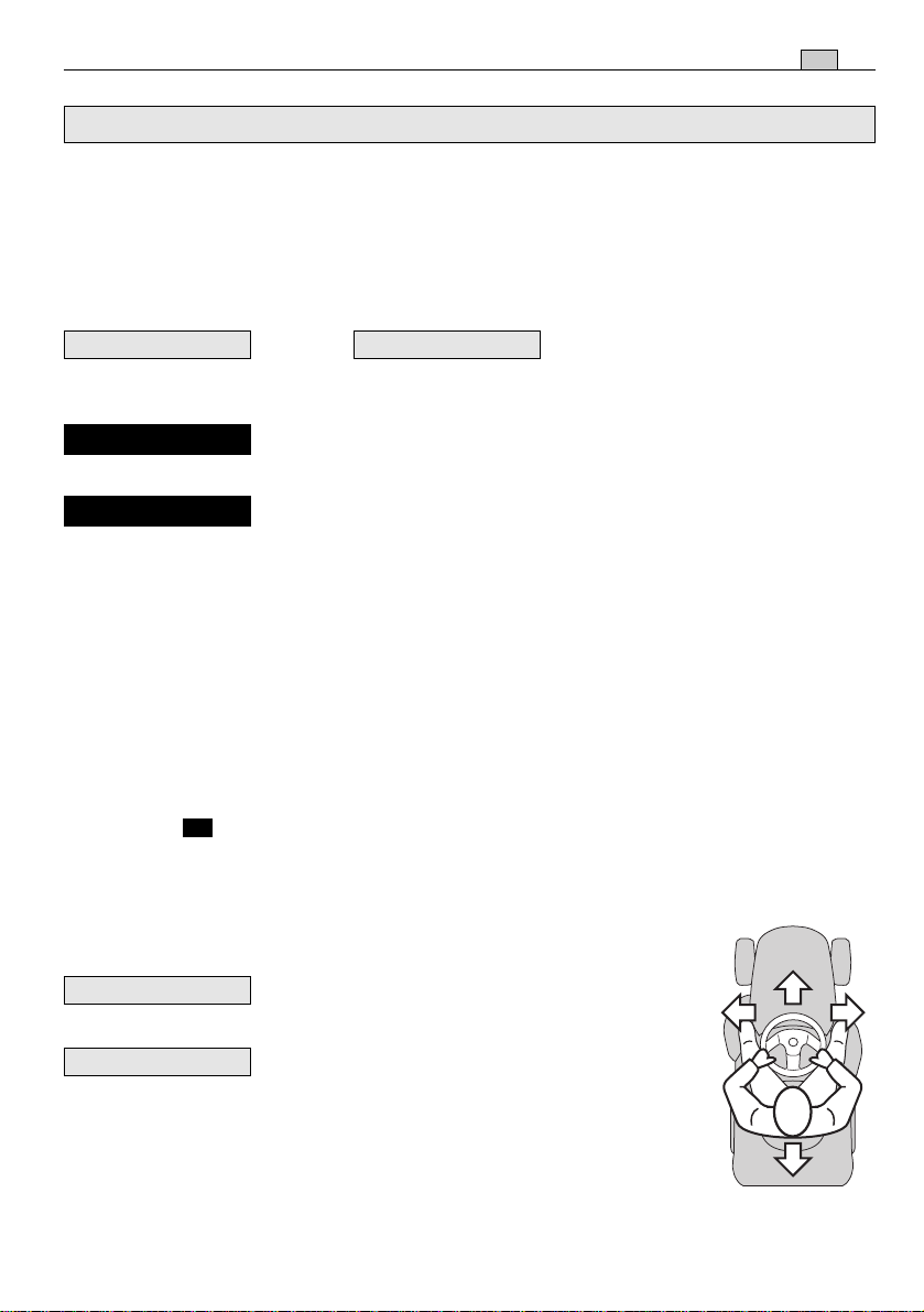
1.3 ÉTIQUETTES DE SÉCURITÉ
Votre machine doit être utilisée avec prudence. Dans ce but, des étiquettes destinées
à vous rappeler les principales précautions d’utilisation ont été placées sur la machine
sous forme de pictogrammes. Ces étiquettes sont considérées comme faisant partie
intégrante de la machine.
Si une étiquette se détache ou devient illisible, contactez votre Revendeur qui veillera
à la remplacer. Leur signification est donnée ci-après.
1
Attention: Lire les instructions
avant d’utiliser la machine.
2
Attention: Enlever la clé de
1
2
contact et lire les instructions
avant toute opération d’entretien
ou de réparation.
3
Danger! Projection d'objets:
3 4
Travailler après avoir monté le
pare-pierres ou le bac.
4
Danger! Projection d'objets:
Les personnes doivent toujours se
5
6
tenir loin de la machine.
5
Danger! Renversement de la
machine: Ne pas utiliser cette
machine sur des pentes supérieures à 10°.
6
Danger! Mutilations: S'assurer que les enfants se tiennent
loin de la machine lorsque le moteur est en marche.
7
Risque de coupure. Lames tournantes. Ne pas introduire
les mains et les pieds dans l’enceinte de lame.
1.4 CONSIGNES POUR LE REMORQUAGE
Un jeu d'accessoires est disponible sur demande: il permet le
remorquage d'une petite remorque; cet accessoire doit être
monté sur la plaque arrière conformément aux consignes fournies. Dans l'emploi de ce jeu, ne pas dépasser les limites de
chargement reportées sur l'étiquette et respecter les normes
de sécurité (☛ 1.2, C-6).
7
max 245 N (25 kg)
max 980 N (100 kg)
IDENTIFICATION DE LA MACHINE ET DE SES PIÈCES
16 17 19 18 15 14
11 12 13
2. IDENTIFICATION DE LA MACHINE ET DE SES PIÈCES
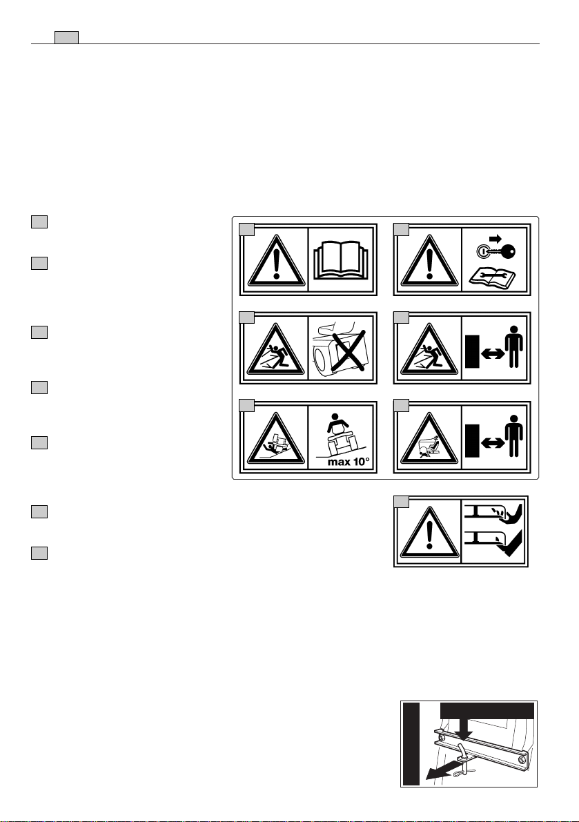
2.1 IDENTIFICATION DE LA MACHINE
L’étiquette appliquée près du compartiment batterie porte les données essentielles de chaque
machine.
1. Niveau de puissance acoustique
selon la directive 2000/14/CE
2. Marquage de conformité selon la
directive 98/37/CEE
3. Année de fabrication
4. Vitesse de service du moteur en tours
par minute (si indiquée)
5. Type de machine
6. Numéro de série
7. Poids en kilogrammes
8. Nom et adresse du Fabricant
9. Type de transmission (si indiqué)
✍
Inscrire ici le numéro de série
de votre machine (6)
8 5 4 7
-1
min
3 9 6 2 1
kg
S/N
FR
L
dB
7
WA
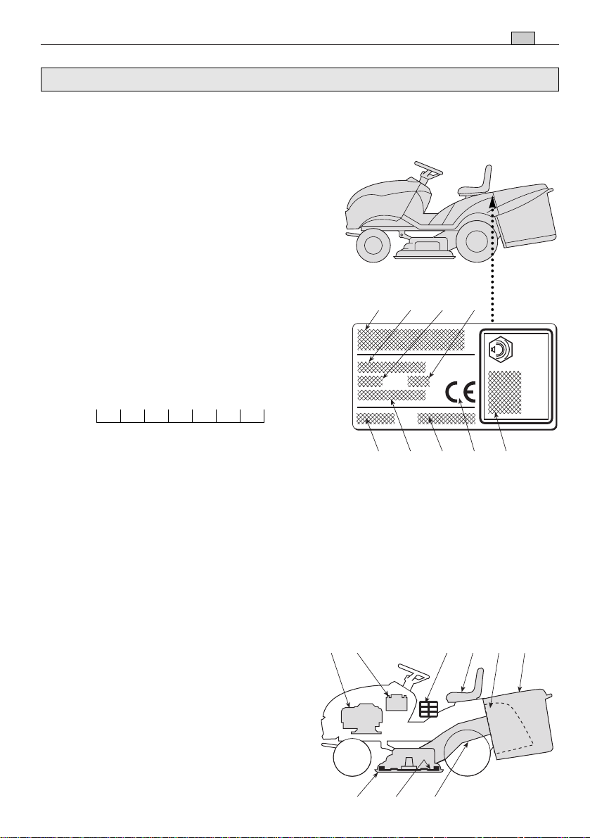
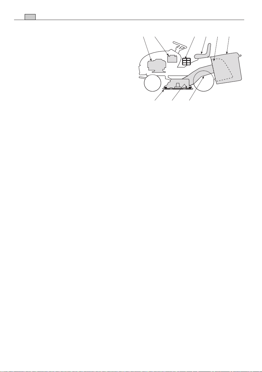
2.2 IDENTIFICATION DES PIÈCES PRINCIPALES
La machine est composée de pièces principales distinctes dont les fonctions sont les
suivantes:
11. Plateau de coupe: c'est le carter qui renferme les lames tournantes.
12. Lames: pièces servant à la tonte du
gazon; les ailettes situées aux extrémités favorisent le passage de la pelouse
tondue vers la goulotte d'éjection.
13. Goulotte d'éjection: pièce permettant
la connexion entre le plateau de coupe
et le bac de ramassage.
14. Bac de ramassage: sert d'une part à
8
16 17 19 18 15 14
11 12 13
FR
IDENTIFICATION DE LA MACHINE ET DE SES PIÈCES
ramasser l'herbe tondue et constitue
d’autre part un élément de sécurité puisqu'il empêche aux objets éventuellement pris par les lames d'être éjectés
loin de la machine.
15. Pare-pierres ou déflecteur (disponible
sur demande): monté à la place du bac
de ramassage, il empêche aux objets
éventuellement pris par les lames d'être
éjectés loin de la machine.
16. Moteur: met en mouvement les lames et permet la rotation des roues; ses caractéristiques sont décrites dans un manuel à part.
17. Batterie: fournit l'énergie pour le démarrage du moteur ; ses caractéristiques sont
décrites dans un manuel à part.
18. Siège de conduite: c'est le poste de travail de l'opérateur ; il est muni d'un capteur qui détecte sa présence pour une intervention des dispositifs de sécurité.
19. Étiquettes de prescriptions et de sécurité: rappellent les principales précautions à prendre pour opérer en toute sécurité; leur signification est fournie dans le
chap. 1.
DÉBALLAGE ET MONTAGE
FR
3. DÉBALLAGE ET MONTAGE
Pour des raisons de stockage et de transport, certains éléments de la machine ne sont
pas assemblés directement en usine mais doivent être montés après déballage. Pour
leur montage, suivre ces consignes.
9
IMPORTANT
La machine est livrée sans huile moteur et sans essence. Avant de
démarrer le moteur, effectuer le plein d'huile et d'essence selon les indications fournies dans le manuel du moteur.
3.1 DÉBALLAGE
Au moment du déballage, veiller à bien récupérer toutes les pièces et l'équipement
fournis et à ne pas endommager le plateau de coupe lorsque la machine descend de
la palette d'emballage.
L'emballage contient:
– la machine;
– le volant;
– le siège ;
– le pare-chocs avant (si prévu);
– la batterie;
– le bac (avec les instructions correspondantes);
– une enveloppe avec:
– les manuels d’instructions et les documents,
– le kit de montage comprenant également un goujon pour le blocage du volant,
– 2 clés de démarrage et un fusible de rechange de 10 A.
REMARQUE
Pour éviter d’endommager le plateau de coupe, le porter à la hauteur maximum et faire très attention au moment de la descente de la palette de base.
➤
Dans les modèles à transmission hydrostatique, pour faciliter la dépose de la
palette et le déplacement de la machine, placer le levier de déblocage de la transmission en pos. «B» (
☛
4.33).
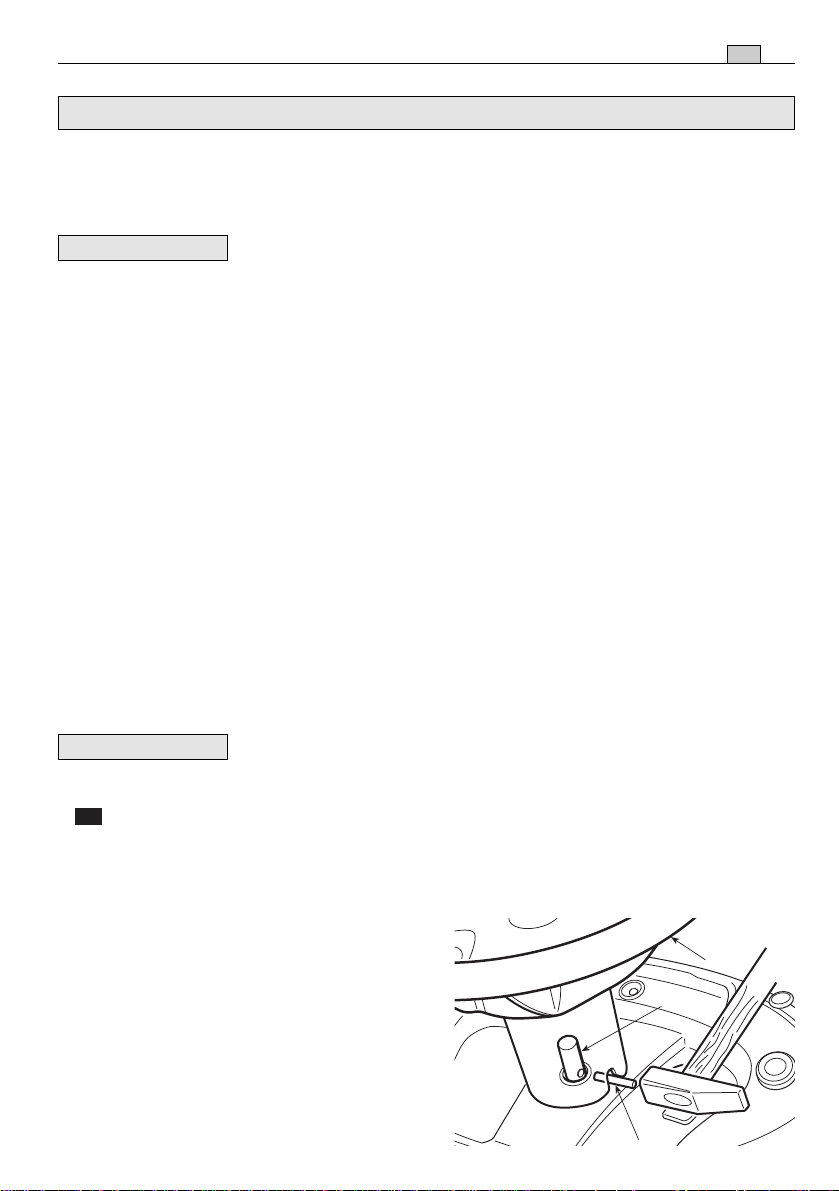
3.2 INSTALLATION DU VOLANT
Disposer la machine sur une surface plane
et aligner les roues avant.
Engager le volant (1) sur la colonne de direction (2) et le tourner de manière à ce que les
rayons soient tournés vers le siège.
Faire correspondre le trou prévu dans l'axe
du volant avec celui de la colonne de direc-
1
2
3
10
FR
DÉBALLAGE ET MONTAGE
tion pour pouvoir y introduire le goujon de blocage (3) fourni, à l'aide d'un marteau, et
s’assurer que l’extrémité sorte complètement du côté opposé.
REMARQUE
Pour éviter d'abîmer le volant avec le marteau, pousser le goujon
à fond avec un pointeau ou un tournevis de diamètre approprié.
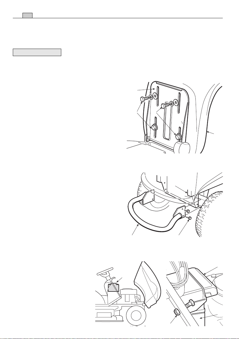
3.3 INSTALLATION DU SIÈGE
2
Monter le siège (1) sur la plaque (2) en utilisant les vis (3).
3 3
3.4 MONTAGE DU PARE-CHOCS AVANT
(si prévu)
Monter le pare-chocs avant (1) sur la partie
inférieure du cadre (2), en utilisant les quatre
vis (3).
1
2
1 3
3.5 MONTAGE ET RACCORDEMENT DE LA BATTERIE
La batterie (1) est logée dans
l'espace moteur, elle est couverte
par une protection (2) et retenue
1
par un collier (3).
Pour enlever la batterie, il faut
dévisser l’écrou (4), démonter la
protection (2) et desserrer le col-
2
1
4

DÉBALLAGE ET MONTAGE
lier (3) en poussant la languette interne à l’aide d’un petit tournevis.
Relier d’abord le câble rouge (8) au pôle
positif (+), et ensuite le câble noir (9) au pôle
négatif (–) à l'aide des vis fournies et en procédant dans l'ordre indiqué.
9
Étendre sur les bornes de la graisse silicone,
et vérifier que le capuchon de protection du
câble rouge (8) est correctement positionné.
1
11
FR
8
Remettre la batterie dans son logement, en
vérifiant que les deux pôles sont tournés
3
vers le centre de la machine, bien serrer le
collier (3) et remonter la protection (2).
IMPORTANT
Procéder toujours à la recharge complète en suivant les indica-
tions du constructeur de la batterie.
IMPORTANT
Afin d'éviter l'intervention de la protection de la carte électronique, il est impératif de ne pas mettre le moteur en marche avant la recharge complète!
!
ATTENTION!
Ne pas utiliser la machine sans la protection (2), ni au cas où
la batterie n’est pas adéquatement fixée dans son logement.
12
FR
COMMANDES ET OUTILS DE CONTRÔLE
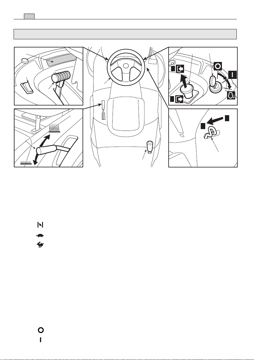
4. COMMANDES ET OUTILS DE CONTRÔLE
4.6
4.5
4.2
4.8
4.1 VOLANT DE DIRECTION
Commande le braquage des roues avant.
4.1
4.9
4.3
4.7
B
A
A
B
4.4
4.2 LEVIER D’ACCÉLÉRATEUR
Règle le nombre de tours du moteur. Les positions sont indiquées sur une plaquette
reportant les symboles suivants:
«STARTER» démarrage à froid
«LENT» régime minimum du moteur
«RAPIDE» régime maximum du moteur
– La position «STARTER» provoque un enrichissement du mélange; elle doit être utili-
sée en cas de démarrage à froid et seulement pendant le temps strictement nécessaire.
– Au cours du déplacement, choisir une position intermédiaire entre «LENT» et «RAPI-
DE».
– Durant la tonte, porter le levier en position «RAPIDE».
4.3 INTERRUPTEUR A CLÉ
Cette commande à clé compte trois positions:
«ARRÊT» correspondant à tout éteint;
«MARCHE» actionne tous les services;
COMMANDES ET OUTILS DE CONTRÔLE
FR
«DÉMARRAGE» actionne le démarreur.
En relâchant la clé à partir de la position «DÉMARRAGE», elle se remet automatiquement sur «MARCHE».
4.4 LEVIER DE FREIN DE STATIONNEMENT
Ce levier sert à empêcher à la machine de se déplacer lorsqu’elle est à l’arrêt. Le levier
d’embrayage a deux positions, correspondant à:
«A» = Frein débrayé
«B» = Frein embrayé
– Pour enclencher le frein de stationnement, appuyer à fond sur la pédale (4.21 ou
4.31) et porter le levier en position «B»; quand on relâche le pied de la pédale, le
frein reste bloqué en position abaissée.
– Pour déclencher le frein de stationnement, appuyer sur la pédale (4.21 ou 4.31),
ainsi le levier se reporte en position «A».
13
4.5 INTERRUPTEUR PHARES ( si prévu)
➤
Commande l'allumage des phares lorsque la clé (4.3) est en position de «MARCHE».
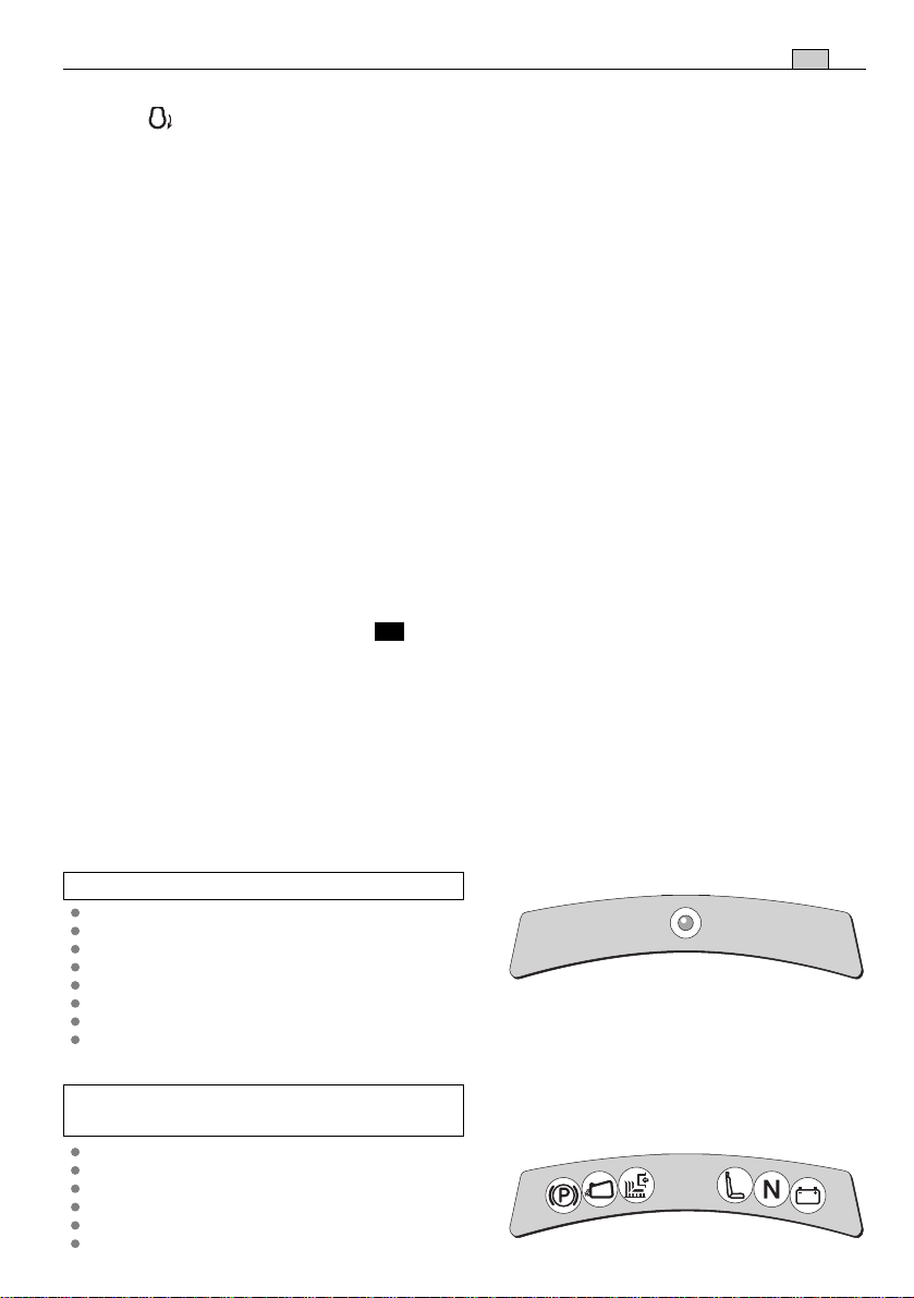
4.6 VOYANTS ET DISPOSITIF DE SIGNALISATION ACOUSTIQUE SUR LE
TABLEAU DE BORD
– Le signal acoustique avertit que le bac est plein (☛ 5.4.6).
➤
Machines avec un seul voyant :
Ce voyant s’allume quand la clé (4.3) se
trouve en position «MARCHE» ; il reste toujours allumé pendant le fonctionnement.
– Quand il clignote, cela signifie qu’il
manque une autorisation au démarrage
du moteur (☛ 5.2).
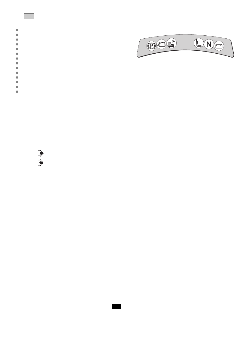
➤
Machines avec tableau de bord à 6
voyants :
Le tableau de bord présente un panneau
c
b
a
d
e
f
avec une série de voyants lumineux qui s’allument lorsque la clef (4.3) est sur
«MARCHE».
14
FR
COMMANDES ET OUTILS DE CONTRÔLE
– Les voyants s’allument en présence de
certaines situations de marche indiquant:
a
c
b
d
e
f
a) frein de stationnement inséré ;
b) absence du sac ou du pare-pierres ;
c) lames embrayées ;
d) absence de l’opérateur ;
e) transmission au “ point mort ”.
f) anomalie dans la recharge de la batterie
(avec le moteur en mouvement).
4.7 COMMANDE D’EMBRAYAGE ET DE FREIN LAMES
L’interrupteur à champignon permet d’insérer les lames grâce à un embrayage électromagnétique:
«A» Appuyé = Lames débrayées
«B» Tiré = Lames embrayées
– Si les lames sont embrayées sans que les conditions de sécurité prévues soient res-
pectées, le moteur s'éteint ou ne peut pas être démarré (☛ 5.2).
– Si les lames sont débrayées (Pos. «A»), un frein est actionné en même temps et
bloque leur rotation en quelques secondes.
4.8 LEVIER DE RÉGLAGE DE LA HAUTEUR DE TONTE
Ce levier se règle sur sept positions marquées de «1» à «7» sur l’étiquette correspondante et indiquant autant de hauteurs de tonte comprises entre 3 et 8 cm.
– Pour passer d'une position à l’autre, pousser le bouton de déblocage placé à l'ex-
trémité du levier.
4.9 LEVIER RENVERSEMENT BAC ( si prévu)
➤
Ce levier, extractible de son siège, permet de renverser le bac pour le vider, en réduisant l’effort que doit fournir l’opérateur.

COMMANDES ET OUTILS DE CONTRÔLE
➤
Transmission mécanique:
4.21
FR
15
N
R
4.22
1
2
3
4
5
4.21 PÉDALE EMBRAYAGE / FREIN
Cette pédale exerce une double fonction: sur la première partie de sa course, elle
actionne l'embrayage en activant ou en arrêtant la rotation des roues ; sur la deuxième, elle agit en tant que frein sur les roues arrière.
IMPORTANT
Ne pas maintenir la pédale dans une position intermédiaire
d’embrayage ou débrayage: la courroie de transmission du mouvement peut surchauffer et s'abîmer.
REMARQUE
Ne pas tenir le pied appuyé sur la pédale pendant la marche.
4.22 LEVIER DE CHANGEMENT DE VITESSE
Ce levier se règle sur sept positions correspondant aux cinq vitesses avant, au point
mort «N» et à la marche arrière «R».
Pour passer d'une vitesse à l'autre, appuyer sur la première partie de la course de la
pédale (4.21) et déplacer le levier selon les indications reportées sur l’étiquette.
!
ATTENTION!
L'embrayage de la marche arrière doit s'effectuer à l'arrêt.
16
FR
➤
Transmission hydrostatique:
COMMANDES ET OUTILS DE CONTRÔLE
4.31 PÉDALE FREIN
Cette pédale actionne le frein sur les roues arrière.
4.32 PÉDALE EMBRAYAGE TRACTION
Cette pédale embraye la traction des roues et permet de régler la vitesse de la
machine, aussi bien en marche avant qu'en marche arrière.
– Pour passer la marche avant, appuyer avec la pointe du pied dans la direction
«F»; en augmentant la pression sur la pédale, on augmente progressivement la
vitesse de la machine.
– Pour passer la marche arrière, appuyer sur la pédale avec le talon dans la direc-
tion «R».
– Quand on relâche la pédale, on retourne automatiquement en position de point
mort «N».
!
ATTENTION!
Le passage de la marche arrière doit être effectué quand la
machine est à l’arrêt.
REMARQUE
Si la pédale de traction est actionnée en marche avant ou en
marche arrière avec le frein de stationnement (4.4) enclenché, le moteur s’arrête.
4.33 LEVIER DE DÉBLOCAGE
4.31
DE LA TRANSMISSION
HYDROSTATIQUE
Ce levier a deux positions, indiquées par une plaquette
«A» = Transmission enclenchée:
pour toutes les conditions
d’utilisation, en marche et
pendant la tonte;
4.32
«B» = Transmission débloquée:
réduit considérablement
l’effort nécessaire pour
N
déplacer la machine à la
main, avec le moteur
éteint.
IMPORTANT
Pour éviter
R
d'endommager le groupe de
transmission, cette opération ne
doit être effectuée qu'à moteur
arrêté, avec la pédale (4.32) en
position «N».
4.33
A
F
B

MODE D’EMPLOI
FR
5. MODE D’EMPLOI
5.1 RECOMMANDATIONS POUR LA SÉCURITÉ
!
DANGER!
destinée (tonte et ramassage de l’herbe).
Ne pas modifier ou enlever les dispositifs de sécurité dont la machine est équipée. NE PAS OUBLIER QUE L'UTILISATEUR EST TOUJOURS RESPONSABLE
DES DOMMAGES CAUSÉS À AUTRUI. Avant d'utiliser la machine:
– lire les consignes générales de sécurité (
toute particulière à la marche et à la tonte sur des terrains en pente;
– lire attentivement les instructions, se familiariser avec les commandes et
apprendre à arrêter rapidement les lames et le moteur;
– tenir les mains et les pieds éloignés des pièces tournantes. Se tenir toujours
à l’écart de la goulotte d’éjection.
Ne pas utiliser la machine en cas de mauvaises conditions physiques ou sous
l’effet de médicaments ou de substances pouvant nuire à la capacité de
réflexes et de vigilance.
Il est de responsabilité de l’utilisateur d’évaluer les risques potentiels du terrain
à travailler et de prendre toutes les précautions nécessaires pour assurer sa
sécurité, et celle d’autrui, en particulier dans les pentes, sur les sols accidentés, glissants ou instables.
Ne pas laisser la machine arrêtée dans l’herbe haute avec le moteur en marche
afin d’éviter de provoquer des incendies.
N’utiliser la machine que pour effectuer ce à quoi elle est
☛
1.2), en accordant une attention
17
!
ATTENTION!
rieures à 10° (17%) (
terrains en pente (jamais supérieure à 10°), il est opportun d'installer des
contrepoids (fournis sur demande
afin d'augmenter la stabilité antérieure de la machine et de réduire la possibilité de cabrage.
IMPORTANT
celles illustrées dans le chapitre 4.
5.2 CRITÈRES D’INTERVENTION DES DISPOSITIFS DE SÉCURITÉ
Les dispositifs de sécurité agissent selon deux critères:
– empêcher le démarrage du moteur si toutes les conditions de sécurité ne sont pas
respectées;
– arrêter le moteur si ne serait-ce qu’une seule condition de sécurité n’est plus res-
pectée.
a) Pour démarrer le moteur, il faut dans tous les cas que:
– la transmission soit au “point mort”;
Cette machine ne doit pas être utilisée sur des pentes supé-
☛
5.5). Si l'on prévoit d'utiliser la machine surtout sur des
☛
8.1) ) sous la traverse des roues avant,
Toutes les références relatives aux positions des commandes sont
18
FR
MODE D’EMPLOI
– les lames soient débrayées;
– l’opérateur soit assis ou que le frein de stationnement soit enclenché.
b) Le moteur s’arrête quand:
– l’opérateur abandonne son siège et que les lames sont embrayées;
– l’opérateur abandonne son siège et que la transmission n’est pas au “point mort”;
– l’opérateur abandonne son siège avec la transmission au “point mort”, mais sans
avoir mis le frein de stationnement;
– on soulève le bac ou on enlève le pare-pierres avec les lames embrayées;
– le frein de stationnement est enclenché sans qu’on ait débrayé les lames.
5.3 OPÉRATIONS À EFFECTUER AVANT DE DÉBUTER LE TRAVAIL
Avant de commencer à travailler, il faut effectuer une série de contrôles et d’opérations
pour assurer que le travail soit effectué de façon profitable et dans des conditions de
sécurité maximales.
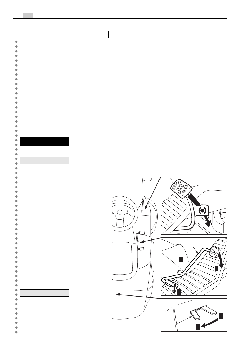
5.3.1 Réglage du siège
Pour modifier la position du siège, il faut desserrer les quatre vis de fixation (1) et faire coulisser le
siège le long des fentes du support.
1 1
Après avoir réglé la position, serrer à fond les
quatre vis (1).
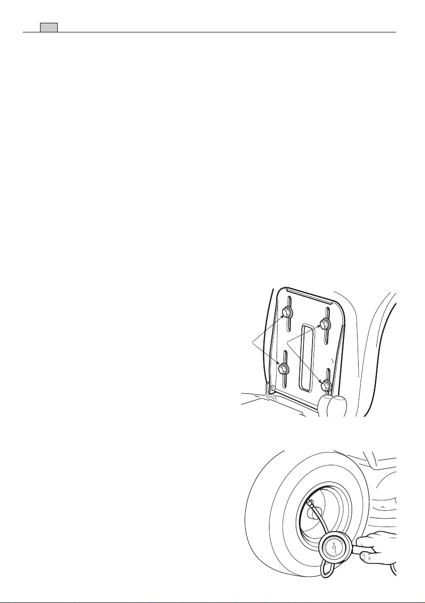
5.3.2 Pression des pneus
Une bonne pression des pneus est la condition
essentielle pour obtenir un alignement parfait du
plateau de coupe et donc une pelouse bien tondue.
Dévisser les bouchons de protection et raccorder les valves à une prise d’air comprimé équipée d’un manomètre.
Les pressions doivent être:
PNEUS AVANT 1.5 bar (13 x 5.00-6)
1.0 bar (15 x 5.00-6)
PNEUS ARRIÈRE 1.2 bar
MODE D’EMPLOI
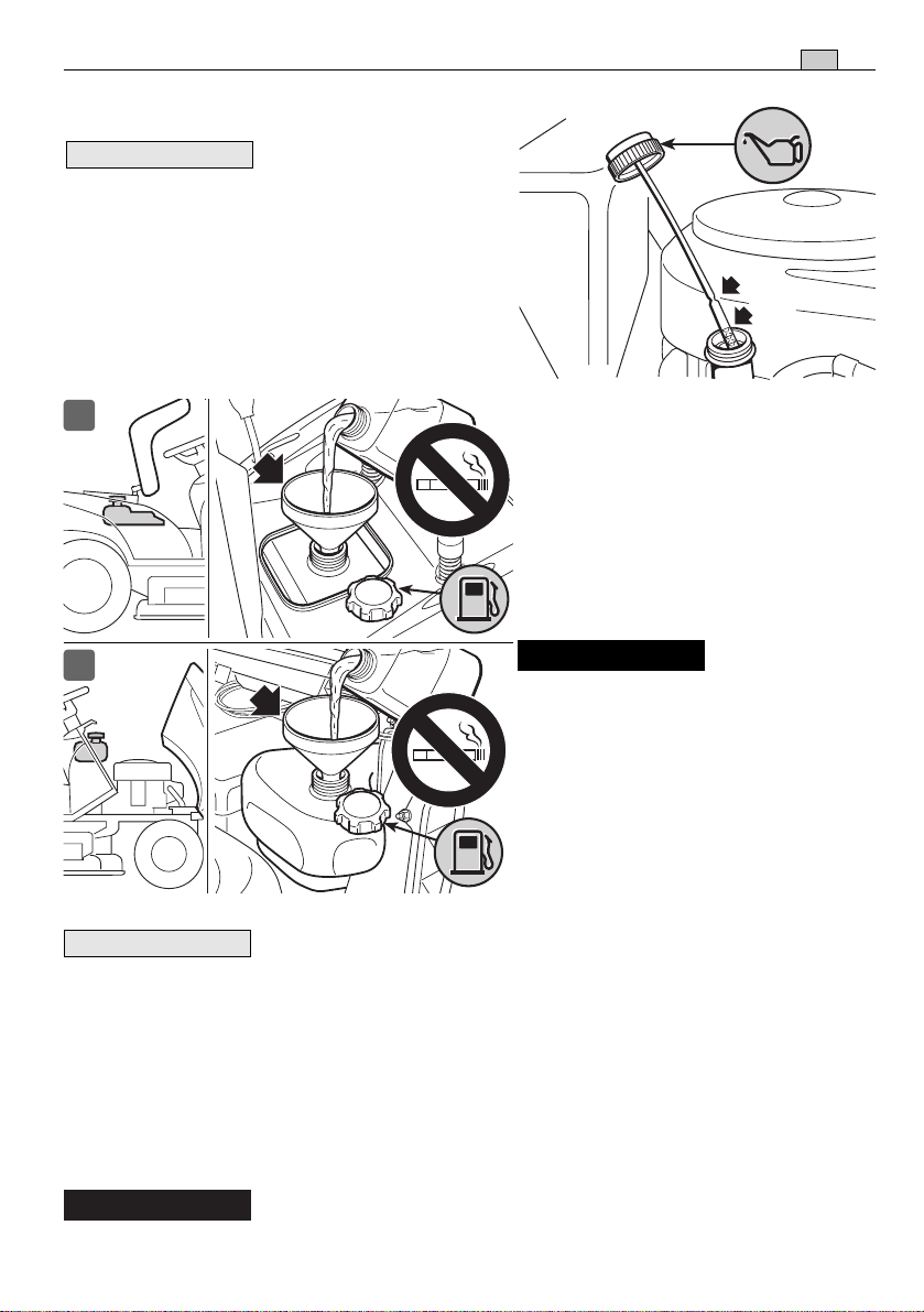
5.3.3 Ravitaillements en huile et essence
FR
19
REMARQUE
Le type d'essence et
d'huile à utiliser est indiqué dans le manuel
d'instructions du moteur.
Couper le contact et contrôler le niveau d'huile
du moteur : selon les modalités indiquées
dans le manuel du moteur, il doit se trouver
entre les encoches MIN et MAX de la jauge.
I
II
MAX
MIN
Faire le plein de carburant à l'aide
d'un entonnoir en ayant bien soin de
ne pas remplir complètement le réservoir.
Le contenu du réservoir est d’environ
6 litres (Type I) ou 4,5 litres (Type II).
!
DANGER!
Le ravitaillement doit s'effectuer lorsque le
contact est coupé, en plein air ou
en tout lieu suffisamment aéré. Ne
pas oublier que les vapeurs d'essence sont inflammables ! NE
JAMAIS APPROCHER UNE FLAMME DU RÉSERVOIR POUR EN
VÉRIFIER LE CONTENU ET NE PAS
FUMER PENDANT LE RAVITAILLEMENT.
IMPORTANT
Éviter de verser de l'essence sur les parties en plastique afin de ne
pas les endommager; en cas de fuites accidentelles, rincer immédiatement à l'eau.
La garantie ne couvre pas les dommages survenus aux pièces en plastique de la carrosserie ou du moteur qui auraient été causés par de l’essence.
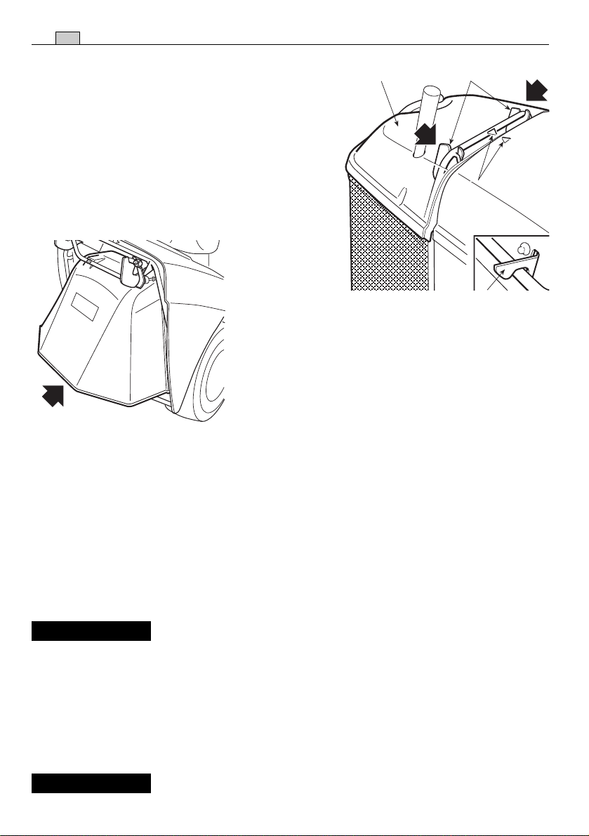
5.3.4 Montage des protections en sortie (bac de ramassage ou pare-pierres)
!
ATTENTION!
Ne jamais utiliser la machine sans avoir installé les protections en sortie!
20
FR
MODE D’EMPLOI
Attacher le bac (1) sur les supports (2) et le centrer
par rapport à la plaque arrière en faisant coïncider
les deux repères (3).
Le centrage est assuré en utilisant le support droit
comme appui latéral.
S’assurer que le tube inférieur de l’entrée du bac se
fixe au crochet de fixation prévu à cet effet (4).
Si l’on désire travailler sans le bac de ramassage,
un kit pare-pierres (☛ 8.2) est disponible sur
demande ; il doit être fixé à la plaque arrière
comme indiqué dans les instructions correspondantes.
5.3.5 Contrôle de la sécurité et de l’efficacité de la machine
21
3
4
1. Vérifier que les dispositifs de sécurité agissent conformément aux indications
(☛ 5.2).
2. S’assurer que le frein fonctionne régulièrement.
3. Ne pas commencer à couper si les lames vibrent ou si l’on a des doutes sur l’affûtage; se rappeler toujours que:
– Une lame mal aiguisée arrache l'herbe et fait jaunir la pelouse.
– Une lame desserrée cause des vibrations anormales et peut provoquer une situa-
tion de danger.
!
ATTENTION!
N’utilisez pas la machine si vous n’êtes pas sûrs de son efficacité ni des conditions de sécurité, et contactez immédiatement votre Revendeur pour toutes les vérifications ou réparations nécessaires.
5.4 UTILISATION DE LA MACHINE
5.4.1 Démarrage
!
DANGER!
Les opérations relatives à la mise en marche doivent s'effec-
MODE D’EMPLOI
FR
tuer en plein air ou en tout lieu suffisamment aéré! NE PAS OUBLIER QUE LES
GAZ D’ÉCHAPPEMENT DU MOTEUR SONT TOXIQUES!
Pour démarrer le moteur:
– ouvrir le robinet d'essence (1) ( si prévu);
– mettre le levier de vitesses au point mort («N») (☛ 4.22
➤
1
ou 4.32);
– débrayer les lames (☛ 4.7);
– enclencher le frein de stationnement, sur les terrains en
pente;
– en cas de démarrage à froid, placer le levier de l'accé-
lérateur sur la position «STARTER» indiquée sur l'éti-
quette;
– en cas de moteur déjà chaud, il suffit de positionner le
levier entre «LENT» et «RAPIDE»;
– introduire la clé, la tourner sur «MARCHE» pour établir le contact électrique, puis la
positionner sur «DÉMARRAGE» pour démarrer le moteur;
– relâchez-la dès qu’il a démarré..
Lorsque le moteur est en marche, positionner l'accélérateur sur «LENT».
21
IMPORTANT
Le starter doit être désactivé dès que le moteur tourne régulièrement; s’il est employé lorsque le moteur est déjà chaud, il peut salir la bougie et causer un fonctionnement irrégulier du moteur.
REMARQUE
Si la mise en marche s'avère problématique, ne pas trop insister
afin de ne pas décharger la batterie et noyer ainsi le moteur. Replacer la clé sur
«ARRÊT», attendre un peu et répéter l'opération. Si le problème persiste, consulter le
chapitre «7» de ce manuel et le manuel d'instructions du moteur.
IMPORTANT
Ne pas oublier que les dispositifs de sécurité empêchent le
démarrage du moteur lorsque les conditions de sécurité ne sont pas respectées
(
☛
5.2).
Dans ces cas, après avoir rétabli la situation d’autorisation de démarrage, il faut
reporter la clé sur «ARRÊT» avant de pouvoir démarrer à nouveau le moteur.
5.4.2 Marche avant et déplacements
!
ATTENTION!
La machine n'est pas homologuée pour circuler sur les voies
publiques. Elle s'utilise exclusivement (conformément au Code de la Route)
dans des zones privées interdites à la circulation
Dans les déplacements, les lames doivent être débrayées et le plateau de coupe mis à
la hauteur maximum (position «7»).

22
FR
➤
Transmission mécanique:
Placer la commande de l'accélérateur dans
MODE D’EMPLOI
une position intermédiaire entre «LENT» et «RAPIDE» et mettre le levier de vitesse
en première (☛ 4.22).
Tenir la pédale appuyée et dégager le frein de stationnement ; relâcher graduellement la pédale, qui passera ainsi de la fonction “ frein ” à la fonction “ embrayage ”,
et actionnera les roues arrière (☛ 4.21).
!
ATTENTION!
Relâcher la pédale graduellement pour éviter qu'un
démarrage trop brusque ne cause le cabrage et la perte de contrôle du véhicule.
Atteindre graduellement la vitesse souhaitée en jouant sur l'accélérateur et le levier
de vitesse; pour changer de vitesse, débrayer en utilisant la première partie de la
course de la pédale (☛ 4.21).
➤
Transmission hydrostatique:
Pour les déplacements, placer le levier de l'accélérateur dans une position intermédiaire entre «LENT» et «RAPIDE».
Déclencher le frein de stationnement et relâcher la pédale du frein (☛ 4.31).
Appuyer sur la pédale de traction (☛ 4.32) ) en direction «F», et atteindre la vitesse
désirée, en agissant sur la pédale et sur l’accélérateur.
!
ATTENTION!
modalités déjà décrites (
L'embrayage de la traction doit être effectué selon les
☛
4.32) afin d’éviter qu'un embrayage trop brusque
ne cause le cabrage et la perte de contrôle du véhicule, en particulier dans les
pentes.
5.4.3 Freinage
Ralentir d’abord la vitesse de la machine en réduisant les tours du moteur puis
appuyer sur la pédale du frein (☛ 4.21 ou 4.31) pour réduire davantage la vitesse, jusqu'à l'arrêt du véhicule.
➤
Transmission hydrostatique:
Un ralentissement sensible de la machine est
obtenu en relâchant la pédale de la traction.

MODE D’EMPLOI
5.4.4 Marche arrière
FR
23
IMPORTANT
➤
Transmission mécanique:
L'engagement de la marche arrière doit s'effectuer à l'arrêt.
Actionner la pédale jusqu'à ce que la machine
s'arrête, enclencher la marche arrière en déplaçant latéralement le levier et en le
positionnant sur «R» (☛ 4.22). Relâcher graduellement la pédale pour embrayer et
ainsi, reculer.
➤
Transmission hydrostatique:
Quand la machine est arrêtée, commencer la
marche arrière en appuyant sur la pédale de traction en direction «R» (☛ 4.32).
5.4.5 Tonte de la pelouse
Pour débuter la tonte:
– placer l'accélérateur sur «RAPIDE»;
– porter le plateau de coupe en position de hauteur maximum;
– embrayer les lames (☛ 4.9);
– avancer très graduellement dans le gazon et en faisant bien attention, comme déjà
décrit précédemment;
– régler la vitesse de marche et la hauteur de tonte (☛ 4.8) selon les conditions de la
pelouse (hauteur, densité et humidité de l'herbe).
!
ATTENTION!
d’avancement pour garantir les conditions de sécurité (
Pour les tontes sur terrains en pente, il faut réduire la vitesse
☛
1.2 - 5.5).
Il est dans tous les cas préférable de réduire la vitesse dès que le moteur peine ; ne
pas oublier en effet que la tonte ne sera jamais bonne si la vitesse est trop élevée par
rapport à la quantité d’herbe coupée.
Débrayer les lames et lever le plateau en position de hauteur maximum dès qu’un obstacle doit être affronté.
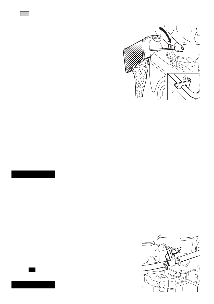
5.4.6 Vidage du bac de ramassage
REMARQUE
N'effectuer cette opération que lorsque les lames sont débrayées;
dans le cas contraire, le moteur s'arrêterait.
Ne pas attendre que le bac se remplisse trop, afin d’éviter que le canal d'éjection ne
se bouche.
24
FR
MODE D’EMPLOI
Un bip sonore signale le remplissage du bac de
ramassage; il convient alors de:
1
– débrayer les lames (☛ 4.7) pour que le bip
sonore s’interrompe;
– réduire le régime du moteur;
– mettre au point mort (N) (☛ 4.22 - Transmis-
sion mécanique ou 4.32 - Transmission
hydrostatique) et s’arrêter ;
– enclencher le frein de stationnement sur les
pentes;
– extraire le levier (1) et renverser le bac pour le
vider ;
2
– refermer le bac de façon à ce qu’il reste fixé au
crochet de fixation (2).
5.4.7 Vidage de la goulotte d’éjection
La tonte d’herbe très haute ou mouillée, unie à une vitesse d’avancement trop élevée,
peut provoquer l’engorgement de la goulotte d’éjection. En cas d’engorgement, il faut:
– s’arrêter, débrayer les lames et couper le contact;
– enlever le bac ou le pare-pierres;
– enlever l’herbe accumulée, en agissant depuis la partie de la bouche de sortie de la
goulotte.
!
ATTENTION!
Cette opération doit toujours être effectuée avec le moteur
coupé.
5.4.8 Fin de la tonte
Après la tonte, débrayer les lames, réduire le nombre de tours du moteur et lever le
plateau de coupe au maximum pour parcourir le trajet de retour.
5.4.9 Fin du travail
Arrêter la machine, positionner le levier de l’accélérateur
1
sur «LENT» et couper le contact en positionnant la clé sur
«ARRÊT».
Lorsque le moteur est à l'arrêt, fermer le robinet (1) d'essence ( si prévu).
➤
!
ATTENTION!
Pour éviter le retour de flamme,
MODE D’EMPLOI
placer l'accélérateur sur«LENT» pendant 20 secondes avant de couper le
contact.
!
ATTENTION!
Ne pas oublier d’enlever la clé de contact avant de laisser la
machine sans surveillance!
FR
25
IMPORTANT
Pour préserver le chargement de la batterie, ne jamais laisser la
clef en position de “MARCHE” lorsque le moteur n’est pas en marche
5.4.10 Nettoyage de la machine
Après chaque utilisation, nettoyer l'extérieur de la machine, vider son bac et le secouer
pour le débarrasser de tout résidu d'herbe ou de terre.
!
ATTENTION!
Vider toujours le bac et ne pas laisser de conteneurs avec
l’herbe coupée à l’intérieur d’un local
Laver les éléments en plastique de la carrosserie à l'aide d'une éponge imbibée d'eau
et de détergent; veiller à ne mouiller ni le moteur ni les composants de l'installation
électrique ni la carte électronique située sous le tableau de bord.
IMPORTANT
Ne jamais utiliser de lances à haute pression ni de liquides agres-
sifs pour laver la carrosserie et le moteur!
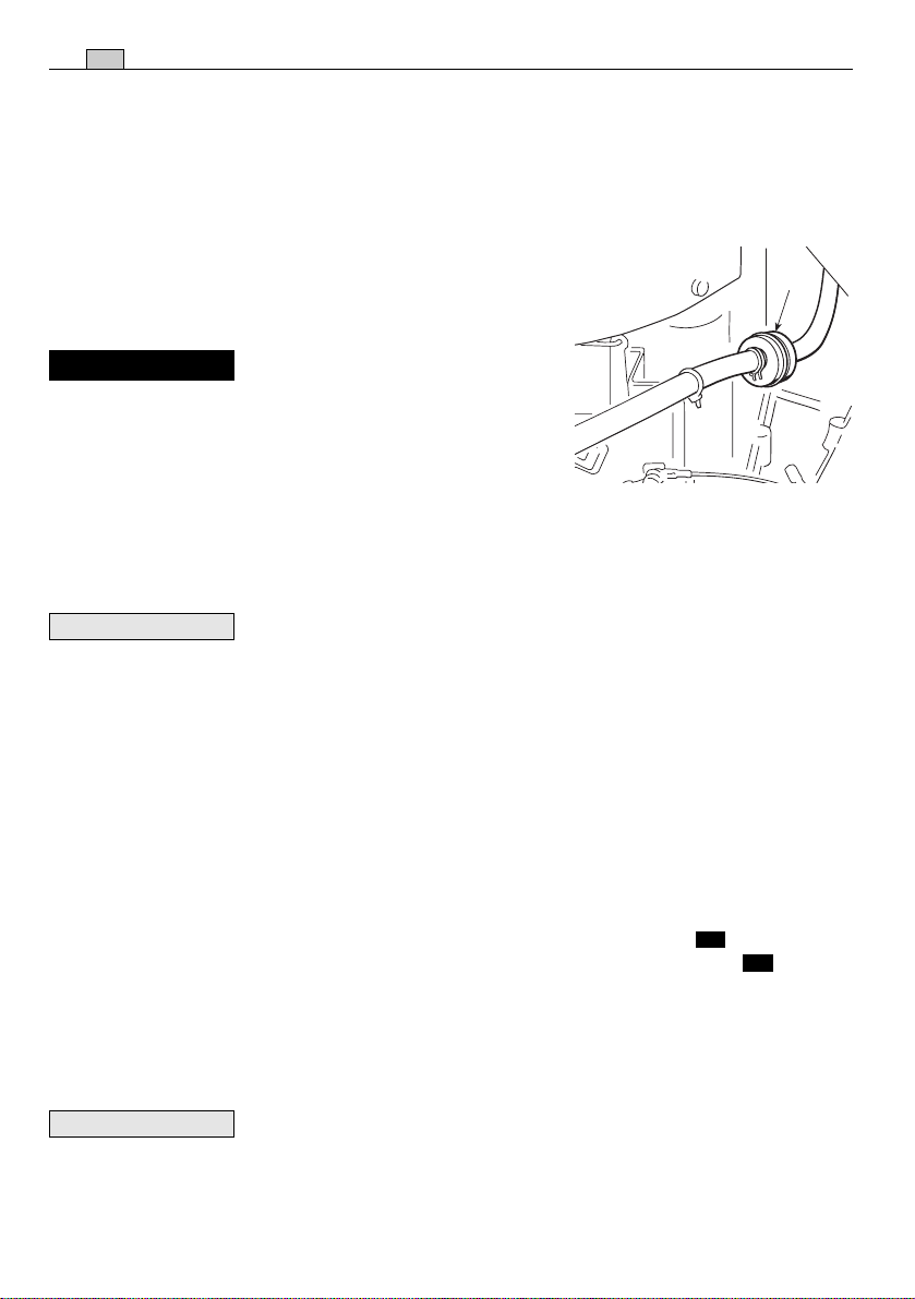
Le lavage de l’intérieur du plateau de coupe et de la goulotte d’éjection doit être exécuté sur un sol résistant, avec:
– le bac ou le pare-pierres monté;
– l'opérateur assis;
– le moteur en marche;
– le changement de vitesses au point mort;
– les lames embrayées.
Relier alternativement un tuyau d’arrosage aux
raccords prévus à cet effet (1) et faire couler
l'eau pendant quelques minutes dans chacun,
avec les lames en mouvement.
Au cours du lavage, il est opportun que le plateau de coupe soit entièrement baissé. Enlever
ensuite le bac de ramassage, le vider, le rincer
et le ranger de telle sorte qu'il puisse sécher
rapidement.
1
26
FR
MODE D’EMPLOI
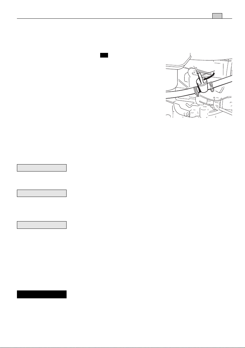
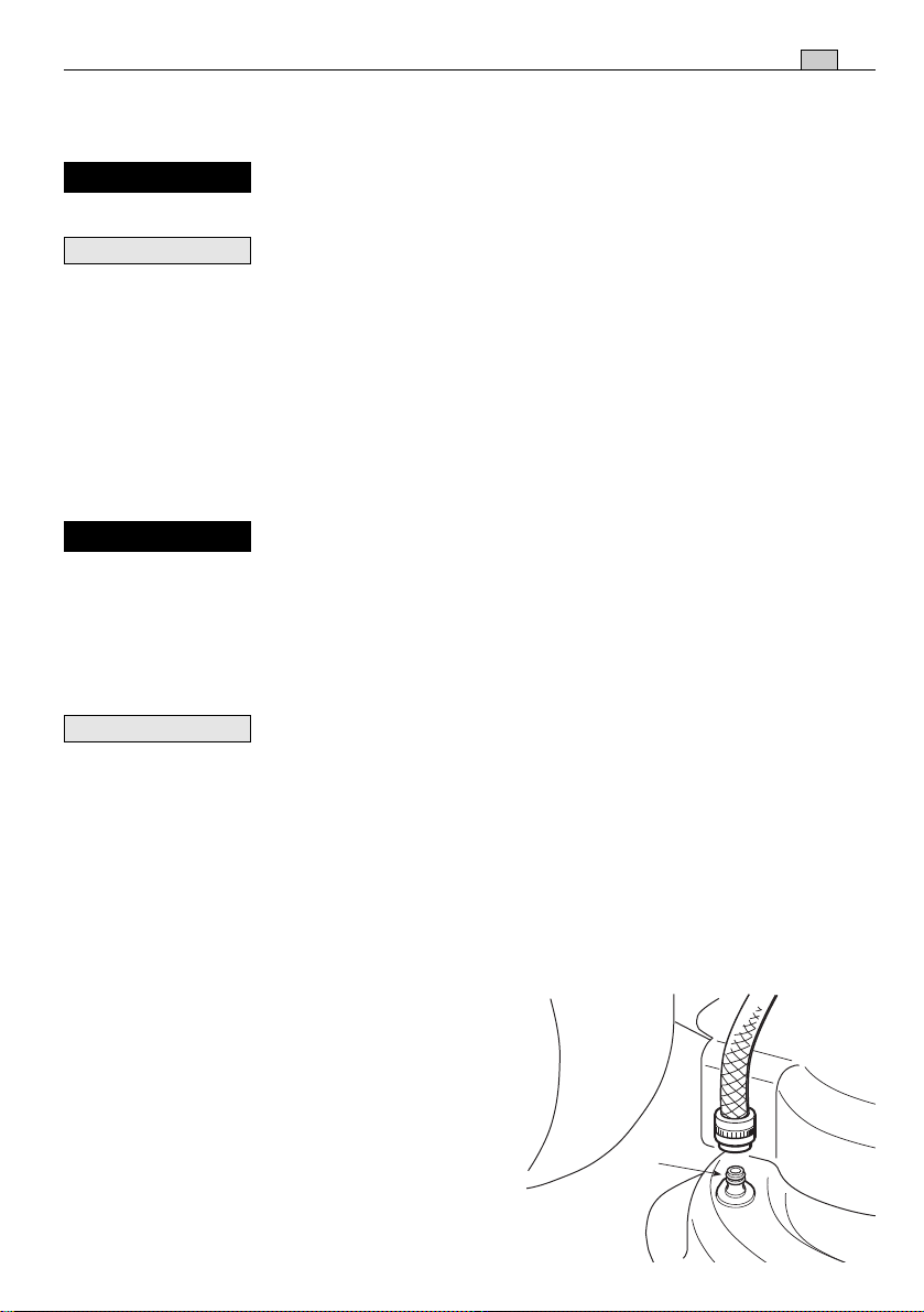
5.4.11 Remisage et inactivité prolongée
En cas d'inactivité prolongée (plus d'un mois), détacher les câbles de la batterie et
suivre les instructions contenues dans le manuel du moteur.
Vider le réservoir carburant en détachant le tube situé à
l'entrée du filtre à essence (1) et suivre les instructions
1
contenues dans le manuel du moteur.
!
ATTENTION!
Prendre bien soin de retirer les
dépôts d'herbe sèche qui se seraient éventuellement accumulés à proximité du moteur et du
silencieux d’échappement: cela évitera d'éventuels débuts d'incendie au moment de la reprise
du travail!
Ranger la machine dans un lieu sec, à l’abri des intempéries et, si possible, la recouvrir
avec une bâche (☛ 8.4).
IMPORTANT
La batterie doit être conservée dans un lieu frais et sec. Avant
une longue période d'inactivité (plus d'un mois), toujours charger la batterie. Ensuite,
avant de reprendre l’activité, procéder à la recharge (
☛
6.2.4).
À la reprise du travail, s’assurer qu'il n'y a pas de fuite d'essence provenant des
tuyaux, du robinet et du carburateur.
5.4.12 Dispositif de protection de la carte
La carte électronique est munie d’une protection à redémarrage automatique qui interrompt le circuit en cas d’anomalies dans l’installation électrique ; cette intervention
provoque l’arrêt du moteur, qui est signalé par l’extinction du voyant ( machines
avec un seul voyant) ou bien par l’extinction complète du tableau de bord (
➤
➤
machines avec tableau de bord à 6 voyants).
Le circuit se remet en marche automatiquement quelques secondes après; rechercher
et éliminer les causes de l’anomalie afin d’éviter que le bip sonore se déclenche à nouveau.
IMPORTANT
Pour éviter l'intervention de la protection:
– ne pas inverser les pôles de la batterie;
– ne pas utiliser la machine sans batterie, pour éviter d’abîmer le régulateur de char-
ge
– veiller à ne pas provoquer de courts-circuits.

MODE D’EMPLOI
FR
5.4.13 Récapitulatif des principales actions a accomplir selon les différentes
situations d’utilisation
Pour ...
Il faut ...
27
Démarrer le moteur (☛ 5.4.1)
Avancer en marche avant (☛ 5.4.2)
Freiner ou s’arrêter (☛ 5.4.3)
Faire marche arrière (☛ 5.4.4)
Tondre la pelouse (☛ 5.4.5)
Vider le bac (☛ 5.4.6)
Désengorger la goulotte (☛ 5.4.7)
Ouvrir le robinet de l’essence, prévoir les situations d’autorisation au démarrage et actionner la clé.
Régler l’accélérateur;
➤
Transmission mécanique: appuyer à fond sur la péda-
le, passer la vitesse ( ☛ 4.22) et relâcher graduellement
la pédale;
➤
Transmission hydrostatique: appuyer en avant la
pédale de la traction (☛ 4.32);
Réduire les tours du moteur et appuyer sur la pédale du
frein.
Arrêter la machine;
➤
Transmission mécanique: mettre au point mort (N),
appuyer à fond sur la pédale, passer la marche arrière
(☛ 4.22) et relâcher graduellement la pédale;
➤
Transmission hydrostatique: appuyer en avant la
pédale de la traction ( ☛ 4.32).
Monter le bac ou le pare-pierres et régler l’accélérateur;
embrayer les lames et régler la hauteur de tonte.
➤
Transmission mécanique: appuyer à fond sur la péda-
le, passer la vitesse ( ☛ 4.22) ) et relâcher graduellement
la pédale;
➤
Transmission hydrostatique: appuyer en avant la
pédale de la traction ( ☛ 4.32);
Arrêter l’avancement, débrayer les lames et actionner le
levier de renversement du bac.
Arrêter l’avancement, débrayer les lames et arrêter le
moteur; enlever le bac et nettoyer la goulotte.
Terminer la tonte (☛ 5.4.8)
Arrêter le moteur (☛ 5.4.9)
Ranger la machine (☛ 5.4.10)
Débrayer les lames et réduire les tours du moteur.
Réduire les tours du moteur, attendre quelques secondes,
actionner la clé et fermer le robinet d’essence.
Enclencher le frein de stationnement, enlever la clé et, si
nécessaire, laver la machine, l’intérieur du plateau de
coupe, la goulotte et le bac.
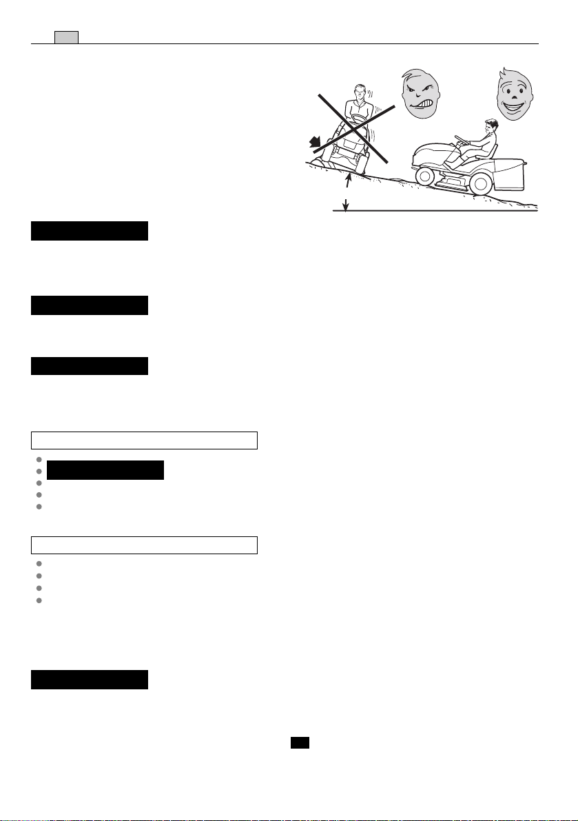
5.5 UTILISATION SUR TERRAINS EN PENTE
Dans le respect des limites indiquées (max 10° - 17%). Les pelouses en pente se ton-
28
FR
dent en montant et en descendant - jamais
transversalement; faire très attention aux
changements de direction: les roues qui se
trouvent en amont ne doivent jamais rencontrer d'obstacles (cailloux, branches, racines,
etc.) susceptibles de faire glisser la machine
sur les côtés, de la retourner ou d'entraîner
une perte de contrôle du véhicule.
max 10° (17%)
!
DANGER!
DIRECTION EN PENTE et ne pas oublier d’enclencher le frein de stationnement
avant de laisser la machine à l'arrêt et sans surveillance.
!
ATTENTION!
faisant très attention pour éviter le cabrage de la machine. Réduire la vitesse
d’avancement avant d’affronter une pente, surtout en descente.
!
DANGER!
cela pourrait provoquer la perte de contrôle du véhicule, surtout sur des terrains glissants.
RÉDUIRE LA VITESSE AVANT TOUT CHANGEMENT DE
Sur les terrains en pente, il faut partir en marche avant en
Ne jamais passer la marche arrière pour réduire la vitesse:
MODE D’EMPLOI
➤
Transmission mécanique:
!
DANGER!
vitesse au point mort ou bien avec la friction débrayée! Passer toujours une
vitesse basse avant de laisser la machine à l’arrêt et sans surveillance.
➤
Transmission hydrostatique:
Parcourir les descentes sans actionner la pédale de la traction (☛ 4.32), afin d’exploiter l’effet freinant de la transmission hydrostatique quand la transmission n’est
pas enclenchée.
5.6 TRANSPORT
!
ATTENTION!
remorque, utiliser des moyens adéquats pour le levage en employant un
nombre de personnes adapté au poids et à la procédure de levage adoptée. La
machine ne doit jamais être soulevée avec des câbles et des palans. Pendant le
transport, fermer le robinet d’essence ( si prévu), abaisser le plateau de
coupe, enclencher le frein de stationnement et fixer adéquatement la machine
au moyen de transport avec des câbles ou des chaînes.
Ne jamais parcourir les descentes avec le changement de
Si la machine doit être transportée sur un camion ou une
➤
MODE D’EMPLOI
FR
5.7 QUELQUES CONSEILS POUR GARDER UNE PELOUSE AYANT UN BEL
ASPECT
1. Pour garder une pelouse ayant un bel aspect, verte et souple, il faut la tondre régu-
lièrement et sans traumatiser l’herbe. La pelouse peut être constituée d’herbes de
typologies différentes. Si l’on tond la pelouse fréquemment, les herbes qui poussent le
plus sont celles qui ont beaucoup de racines, qui forment une couverture herbeuse
solide; si au contraire on la tond moins fréquemment, il se développe des herbes
hautes et sauvages (trèfle, marguerites, etc.).
2. Il est toujours préférable de tondre l’herbe quand la pelouse est bien sèche.
3. Les lames doivent être intègres et bien affilées, de façon à ce que la coupe soit
nette et sans effilochements qui entraînent un jaunissement des pointes.
4. Le moteur doit être utilisé au maximum des tours, aussi bien pour assurer une tonte
nette de l’herbe que pour obtenir une bonne poussée de l’herbe coupée à travers la
goulotte d’éjection.
5. La fréquence des tontes doit être proportionnelle à la croissance de l’herbe, en évi-
tant qu’entre une tonte et l’autre l’herbe pousse trop.
6. Pendant les périodes les plus chaudes et sèches, il est conseillé de garder l’herbe
légèrement plus haute afin de réduire le dessèchement du terrain.
29
7. La hauteur optimale de l’herbe
2
d’une pelouse bien soignée est d’environ 4-5 cm; à chaque coupe il serait
préférable de ne pas enlever plus d'un
tiers de la hauteur totale. Lorsque l'herbe est très haute, il vaut mieux la
tondre en deux fois, à un jour d’intervalle: passer une première fois sur la
pelouse avec les lames levées au maximum et avec une largeur éventuellement réduite; passer la deuxième fois à
la hauteur désirée.
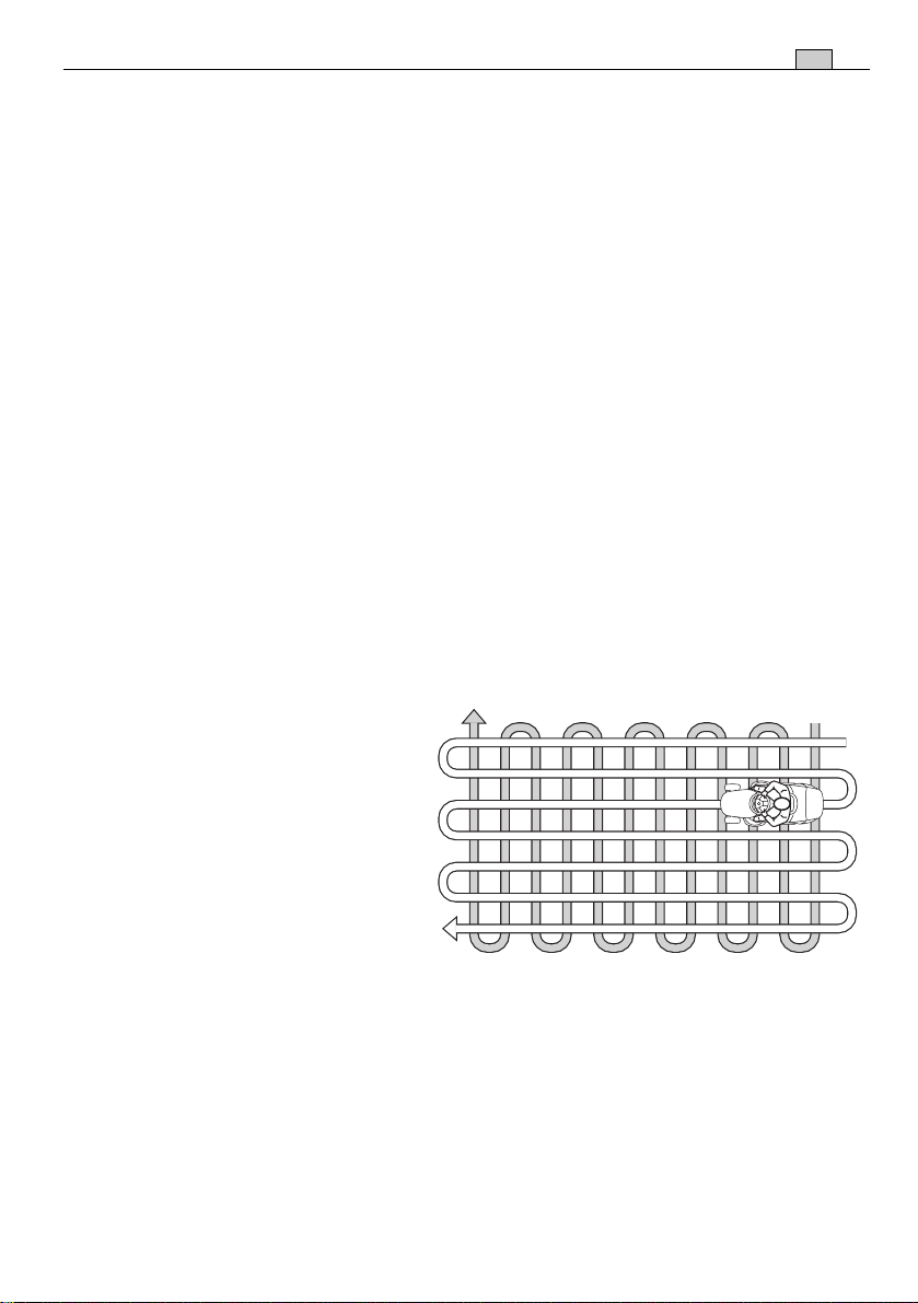
8. L’aspect de la pelouse sera meilleur si les tontes sont exécutées en les alternant
dans les deux directions.
9. Si la goulotte d'éjection se bouche, réduire la vitesse de déplacement car celle-ci
peut être excessive par rapport aux conditions du gazon; si le problème persiste, les
couteaux ne sont pas assez aiguisés ou le profil des ailettes est déformé.
10. Faire très attention à proximité des buissons et des bordures car ils pourraient
endommager le parallélisme, le bord du plateau de coupe et les couteaux.
1
 Loading...