

Page 1
AIR CONDITIONER
SPLIT WALL-MOUNTED
INSTALLATION INSTRUCTIONS
MODELS: WS 090C / WS 090H / WS100H
EMAILAIR
Page 2
Select the location considering the following:
INDOOR UNIT
1. Choose a location which will provide good air circulation. Ensure that
no objects or furnishings prevent air circulation.
2. Do not install the unit near a heat source or where it will be exposed
to direct sunlight.
3. The location must allow convenient electrical drainage and tubing
connections.
4. Installation site should provide an easy passage to outdoors.
5 .The unit must be mounted on a strong wall that will withstand vibration-
generated noise.
6. Install the mounting plate as shown.
LOCATION OF INDOOR AND
OUTDOOR UNITS
OUTDOOR UNIT
1.The location must allow easy servicing and provide good air circulation.
2. The unit may be suspended from a wall by a bracket (optional) or
located in a free standing position on the floor (preferably slightly
elevated).
3. Before the unit is suspended, ensure that the bracket is firmly
connected and the wall is strong enough to withstand vibrations..
4 .Unit location should not disturb neighbors with noise or exhaust air
stream.
5. Place the mounting pads under the unit legs.
6. Install the outdoor unit as shown. Refer to the technical and service
manual for allowed distances.
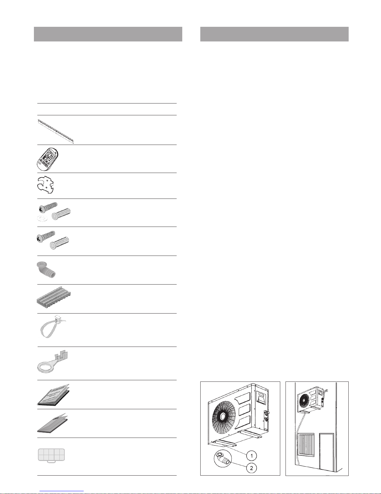
7. When the unit is installed on a wall, install the drain connector hose
as shown.
Fig. 1
1. Bottom of outdoor unit
2. Drain connector
Fig. 2
Drain installation
example
ACCESSORIES SUPPLIED
WITH THE AIR CONDITIONER
2
Fig 1
Fig 2
1
Used for
Qty
Shape Name
Remote control
with batteries
Operation
of unit
1
Remote control
bracket
Wall mounting of
remote control
1
Screws Washers
Dowels
Wall mounting of
indoor unit
4
Screws, Dowels
Wall mounting
of the remote
control bracket
2
Outdoor unit
water drain
Outdoor unit
drain connector
1
Mounting
pads
Padding of
outdoor unit
bottom supports
4
Cable ties
Securing wires in
the indoor and
outdoor unit
4
Cable terminals 1
Securing of
grounding wire on
the indoor and
outdoor unit
Operation
instructions
Users'
reference
1
Installation
instructions
and template
Installers'
reference
1
Air purifying
filter (Optional)
Cleaning
the air
2
Mounting
rail
Wall mounting
of indoor unit
1
Page 3
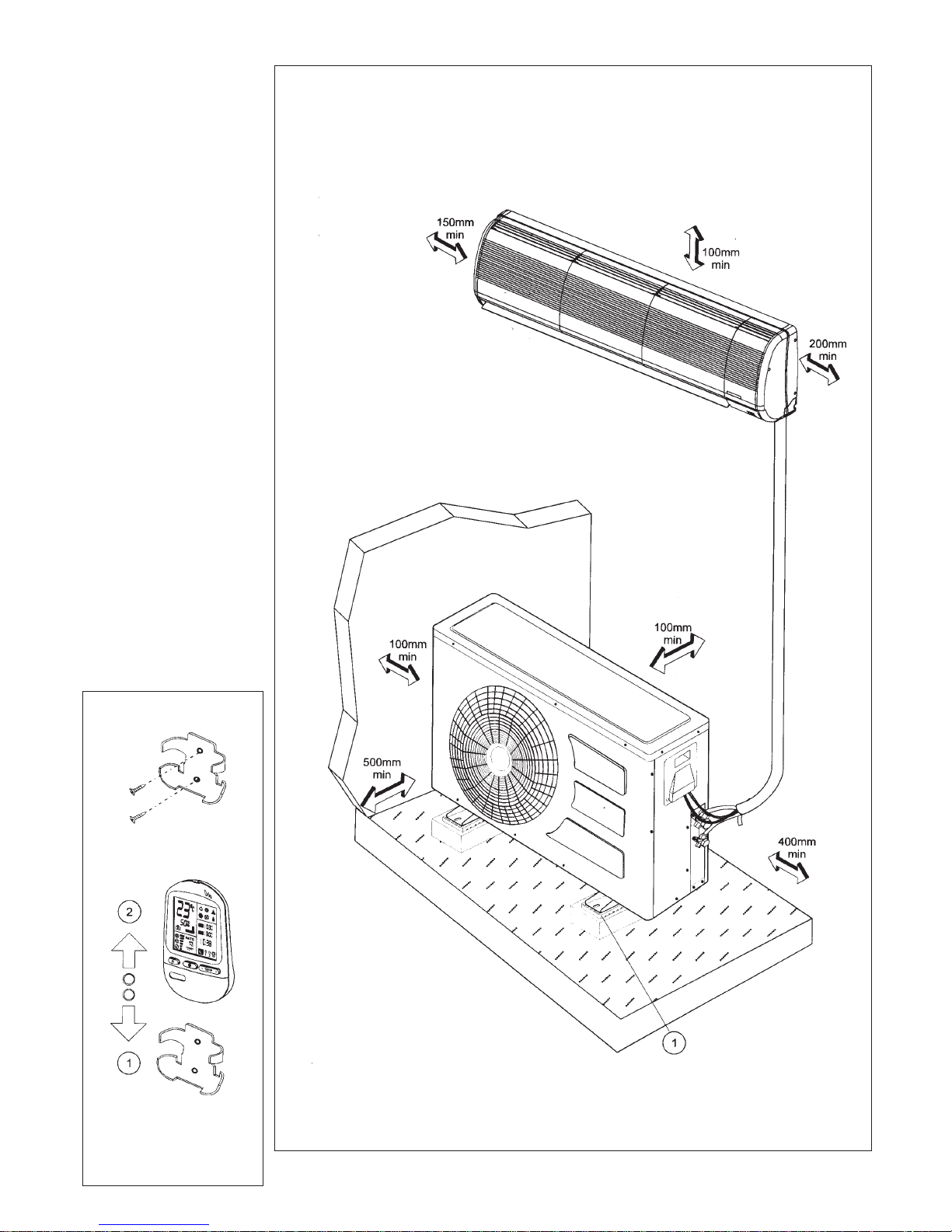
Fig. 3
1. To attach
2. To remove
Fig. 4
1. Mounting pads (
x
4)
Fig 3
Fig 4
Page 4
3
4
Electrical wiring and connections should be made by qualified electricians
and in accordance with local electrical codes and regulations. The air
conditioner units must be grounded.
The air conditioner unit must be connected to an adequate power outlet
from a separate branch circuit protected by a time delay circuit breaker,
as specified on unit's nameplate.
Voltage should not vary beyond ±10% of the rated voltage.
REFRIGERATION TUBE ROUTING
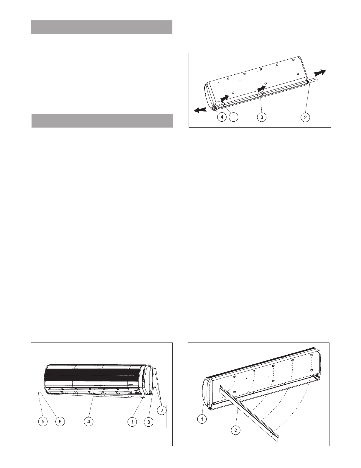
1. There are four possible routes for installing the refrigeration tube as
shown.
2. For routes (2) or (4), cut the side notches in the left or right panel.
Fig.5
1. Right cover
2. Screw caps
3. Screw
4. Bottom cover
5. Screw caps
6. Screws
INSTALLATION OF THE INDOOR UNIT
INSTALLATION OF THE FRONT INDOOR UNIT
Removal of the right cover
1. Remove screw caps (2) from cover (1).
2. Remove the three screws (3).
3. Rotate the right cover to remove it.
Removal of the bottom cover
1. Remove screw caps (5) from the air outlet.
2. Loosen the screws (6) of the air outlet.
3. Pull the cover (4) down and then to the right to disengage it.
ELECTRICAL REQUIREMENTS
3
4
Fig 5
INSTALLATION OF THE MOUNTING RAIL
1. Figure 7 shows the location of the mounting rail relative to the unit
size.
2. Locate the mounting plate as shown on the wall in a horizontal
position, using a spirit level.
3. Mark the position of the four mounting holes on the wall and drill
holes to accommodate the dowels.
4. Mount the mounting rail on to the wall by the screws. Ensure screws
are tightened properly.
5. Mount the unit on the mounting rail.
Fig.7
1. Indoor unit.
2. Mounting rail.
Fig 7
Fig.6
1. Righthand rear outlet
2. Lefthand outlet
3. Lefthand rear outlet
4. Righthand outlet
Fig 6
Page 5
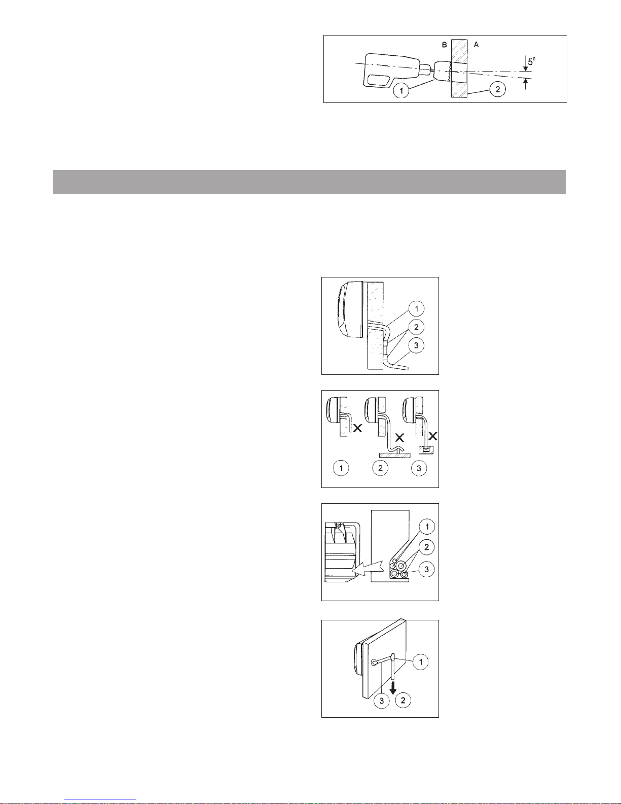
7. Upon completing the installation, test the water drain by pouring at
least two liters of water into the unit drainpan.
Check that the water drains off.
Fig. 8
A. Outdoor side
B. Indoor side
1. Drill Ø70 mm
2. Wall
CONDENSATE HOSE CONNECTION
1. Attach the condensate drain hose to the corrugated hose in the rear
groove of the indoor unit.
2. Wrap the drain hose together with the refrigerant tubes and electrical
cables.
PENETRATION OF WALL FOR TUBING
1. Mark the location of the hole on either side, according to tubing
routings, as shown. and drill it at a 5˚downward angle, as shown.
2. The hole is drilled at an angle to prevent condensed or rain water
from penetrating back into the room.
3.Trim the hole in the wall with a ø70 mm commercial plastic tube.
Fig 8
4. When installing the drain hose avoid traps and U-bends. The end of
the drain hose should not be immersed in water.
Fig. 10
1. Trap
2. U-bend
3. End immersed in water
5. For a lefthand outlet, lay the drain hose on the bottom of the indoor
unit rear groove.
Fig. 11
1. Electric cable
2. Refrigerant tubing
3. Condensate drain hose
6. When the installation location requires long horizontal sections, a vent
must be provided at the top of the hose to prevent overflow of the unit
drain pan.
Fig. 12
1. Vent
2. Downword drain
3. Water drain hose
3. Ensure that the condensate drain hose is installed at all points in a
downward slope manner.
Fig. 9
1. Drain hose
2. Clamp
3. Downward slope
5
Fig 11
Fig 12
Fig 9
Fig 10
Page 6
ELECTRICAL CONNECTIONS
BETWEEN INDOOR AND
OUTDOOR UNITS
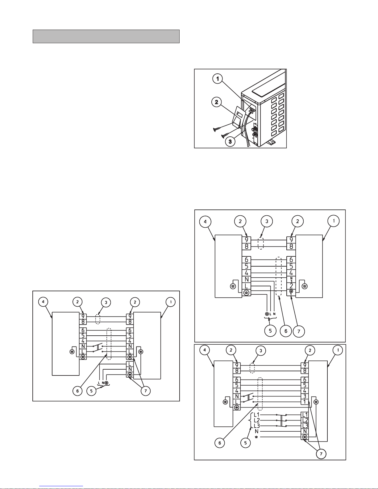
1. To connect the indoor unit with the outdoor unit use the
following electrical cables, protected for outdoor use:
(see Fig. 14a)
Multiwirecable:
5 wires x 2.5 mm²
Twin wire cable:
2 wires x 0.5
SINGLE PHASE MODELS
Cooling and heating model:
mm² - For low voltage.
Multiwirecable:
4 wires x 2.5 mm².
Twin wire cable:
2 wires x 0.5 mm² - For low voltage.
(see Fig.14b)
The main power supply (5) will be connected to the outdoor
unit.
(see Fig. 14c)
The main power supply electrical cable must be of
H05VV-K5G type and contain 5 x2.5 mm² conductors,
connected to a thermally protected circuit breaker 3 x 12.5A.
2. Prepare inter-unit cable ends for connections.
3. Connect the cable ends to the terminals of the indoor and
outdoor unit, as shown in Fig. 14a, Fig. 14b and Fig. 14c.
Be sure to match the colored wires with the numbers shown
on the indoor and outdoor unit terminal boards.
4. Connect the yellow/green ground wire to the ground terminal
screw.
5. Secure multiple wire power cable with the cable clamps.
6. Fasten the twin wire cable to the power cable with cable ties.
Cooling only model:
For units above 10 KW
THREE PHASE MODELS
Fig. 13
1. Terminals 2. Cover 3. Cable tie
NOTES:
1. The wire color codes can be selected by the installer.
2. Wires leading to terminals 8 and 9 must be in a separate twin
wire cable, otherwise the electronic controls will be subject to
operational malfunctions.
3. For cooling only model. Wire (5) should not be connected to
terminal No. 5.
4. In some models the twin wire cable is factory-connected to the
indoor unit.
Fig. 14a/14b/14c
1. Outdoor unit
2. Terminal board
3. Control cable
4. Indoor unit
5. Power supply
6. Electrical interconnecting cable
7. Terminal board male/female
Fig. 13
6
Fig. 14c
Fig. 14a
Fig. 14b
Page 7
CONNECT THE INDOOR TO THE OUTDOOR UNIT
The indoor unit contains a small quantity of Helium. Do not unscrew the
nuts from the unit until you are ready to connect the tubing. The outdoor
unit is supplied with sufficient refrigerant charge for a 6 m tubing length.
For additional charge, please refer to outdoor unit nameplate.
To prevent crushing, bend tubes using a bending tool.
NOTE: Use refrigeration type copper tubing only.
1. Use tubing diameter that corresponds to the tubing diameter of the
indoor and outdoor units . Note that the liquid and suction tubes have
different diameters. (See tube size, torque tightening table.)
2.Place flare nuts on tube ends before preparing them with a flaring tool.
Use the flare nuts that are mounted on the supplied outdoor and indoor
units.
3. Connect the four ends of the tubing to the indoor and outdoor units.
4. Insulate each tube separately, and their unions, with at least 6 mm of
insulation. Wrap the refrigerant tubing, drain hose and electric cables
together with a vinyl tape (UV protected).
REFRIGERANT TUBING
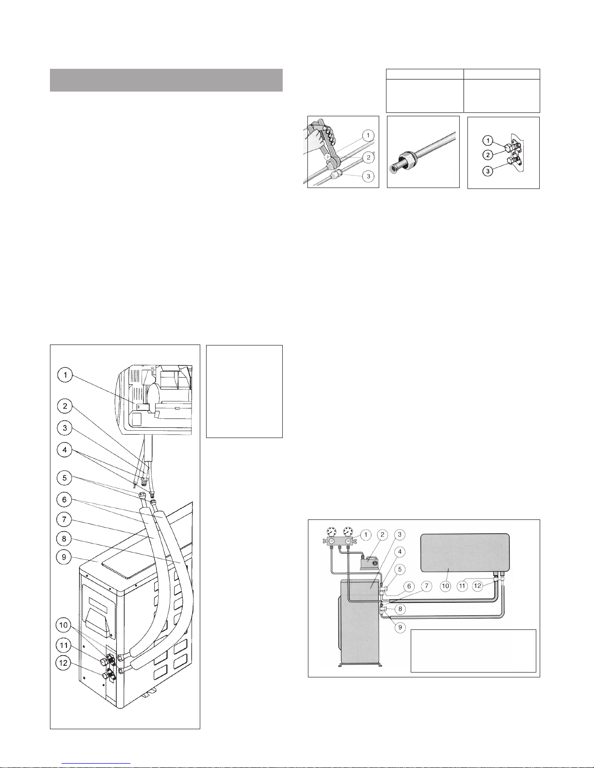
Fig. 15
1. INDOOR UNIT
2. Liquid tube (small dia.)
3. Suction tube (large dia.)
4. Plugs
5. Flare nuts
6. Tubing insulation
7. Suction tube
8. Liquid tube
9. OUTDOOR UNIT
10. Flare nuts
11. Suction valve (larger)
12. Liquid valve (small)
Caution!
When unscrewing
the valve caps, do
not stand in front of
them or the
spindles at any
time, as the system
is under pressure.
Fig 15
7
Tightening
torques of unions
and valve caps:
TUBE SIZE TORQUE
Liquid line 3/8"
Suction line 1/2"
Suction line 5/8"
Suction line 3/4"
30-35 N.M.
50-54 N.M.
75-78 N.M.
80-100 N.M.
Fig. 16
1. Wrench
2. Torque wrench
3. Union
Fig. 18
1. Suction valve
2. Service port
3.Liquid valve
Fig. 17
To prevent refrigerant
leakage, coat the flared
surface with
refrigeration oil
Fig 16
Fig 17
Fig 18
EVACUATION OF THE REFRIGERATION TUBES AND THE INDOOR
UNIT
After connecting the unions of the indoor and outdoor units, purge the
air from the tubes and indoor unit as follows:
1. Connect the charging hoses with a push pin to the low and high sides
of the charging set and the service port of the suction and liquid valves.
Be sure to connect the end of the charging hose with the push pin to the
service port.
2. Connect the center hose of the charging set to a vacuum pump.
3. Turn on the power switch of the vacuum pump and make sure that
the needle in the gauge moves from 0 MPa (0 cm Hg) to -0.1 MPa
(-76 cm Hg). Let the pump run for fifteen minutes.
4. Close the valves of both the low and high sides of the charging set
and turn off the vacuum pump. Note that the needle in the gauge should
not move after approximately five minutes.
5. Disconnect the charging hose from the vacuum pump and from the
service ports of the suction and liquid valves.
6. Tighten the service port caps of both suction and liquid valves.
7. Remove the valve caps from both valves, and open them using a
hexagonal Allen wrench.
8. Remount valve caps onto both of the valves.
9. Check for gas leaks from the four unions and from the valve caps.
Test with electronic leak detector or with a sponge immersed in soapy
water for bubbles.
Fig. 19
1. Charging set
2. Vacuum pump
3. OUTDOOR UNIT
4. Service valve
5. Cap
6. Suction valve
7. Service valve*
8. Cap
9. Liquid valve
10. INDOOR UNIT
11. Suction flare connection
12. Liquid flare connection
* In some models only
NOTE: For additional R-22 charge of
various tubing lengths, refer to
outdoor unit nameplate.
Fig 19
Page 8

FINAL TASKS
1. Replace all valve caps and ensure that they are tightened properly.
2. Fill gaps on the wall between hole sides and tubing with sealer.
3. Attach wiring and tubing to the wall with clamps where necessary.
4. Operate the air conditioner together with the customer and explain all
functions.
5. Explain filter removal, cleaning and installation.
6. Give the operating and installation manuals to the customer.
8
Page 9

745 Springvale Road
Mulgrave, Victoria 3170 Tel: (03) 9271 3505 Fax: (03) 9271 3515
MULGRAVE
745 Springvale Road
Mulgrave, Victoria 3170 Tel: (03) 9271 3534 Fax: (03) 9271 3540
SILVERWATER
46-48 Derby Street
Silverwater, NSW 2128 Tel: (02) 9202 0444 Fax: (02) 9202 0488
ARCHERFIELD
4 Parkview Drive
Archerfield, Qld. 4108 Tel: (07) 3274 4177 Fax: (07) 3274 4152
TOWNSVILLE
1-5 Everett Street PO Box 149
Bohle
Townsville, Qld. 4818 Tel: (07) 4774 6552 Fax: (07) 4774 4967
OSBORNE PARK
19 Howe Street
Osborne Park, WA 6017 Tel: (08) 9244 5699 Fax: (08) 9244 5437
ADEL AID E
Suite 27, 8 Greenhill Road
Wayville, SA 5034 Tel: (08) 8372 7866 Fax: (08) 8372 7816
ECP (AUSTRALIA) PTY LTD ACN 082 755 655
HEAD OFFICE
V
ICTORI
A
NEW SOUTH WALES
QUEENSLAND
SOUTH AUSTRALI
A
/
NORTHERN TERRITORY
WMN RC2 / CAT. NO. 439533 / ENGLISH / REV.05 02/2000
 Loading...