

EM Acoustics EMS Series, EMS-121, EMS-81i, EMS-81, EMS-121w User Manual
...
EMS Series
User Manual – v2.0
EMS-81/EMS-81i
EMS-121/EMS-121w/EMS-121i/EMS-121h
EMS-152/152w
EMS-215/EMS-215i
EM Acoustics Loudspeakers
Building 74, Dunsfold Park
Cranleigh, Surrey
GU6 8TB, UK
Phone +44 (0) 1483 266520
Fax +44 (0) 1483 275619
www.emacoustics.co.uk
_________________________________________________________________________________________
Copyright EM Acoustics 2006
1
EMS Series User Manual
www.emacoustics.co.uk

CONTENTS
Introduction
Thank you ...……………………………………………………………………………………………………………………………. 3
Unpacking ……………………………………………………………………………………………………………………………….. 3
Declaration of Conformity …………………….…………………………………………………………………………………… 3
Product Range Overview
EMS-81 passive two-way fullrange enclosure ……………………………………………………………………………… 4
EMS-121 passive two-way fullrange enclosure ……………………………………………………………………………. 5
EMS-152 passive two-way fullrange enclosure ……………………………………………………………………………. 6
EMS-215 subwoofer …………………………………………………………………………………………………………………. 7
System Set-up
Safety Considerations………………………………………………………………………………………………………………… 8
Cabling & Amplifier selection ……………………………………………………………………………………………………… 9
Mounting & Rigging Options
Rigging Hardware & Accessories ………………………………………………………………………………………………… 10
Permanent Installations …………………………………………………………………………………………………………….. 10
Vertical Flying Cradle Use ……………………………….…………………………………………………………………………. 11
Horizontal Flying Cradle Use …….…………………………………………………………………………………................ 12
Dual Enclosure Flybar Use ………………………………………………………………………………………………. …………13
EMS-152 Rigging Options …………………………………………………………………………………………………………… 14
Ommimount/Powerdrive Bracket Use …………………………………………………………………………………………… 15
DA-1 Amplifier Installation ………………………………………………………………………………………………………………………16
Maintenance
EMS-81 Drive Unit Service ………………………………………………………………………………………………………….17
EMS-121 Drive Unit Service ………………………………………………………………………………………………………. 18
EMS-152 Drive Unit Service ………………………………………………………………………………………………………. 19
EMS-215 Drive Unit Service ………………………………………………………………………………………………………. 20
Warranty ……………………………………………………………………………………………………………………………………………. 21
Appendix A – Technical Specifications …………………………………………………………………………………………………… 22
2
EMS Series User Manual
www.emacoustics.co.uk

INTRODUCTION
Thank you
Thank you for purchasing a product from the acclaimed EMS Series from EM Acoustics. The EMS Series products
have been carefully designed and rigorously tested to ensure years of flawless operation and unprecedented sonic
quality. Flexibility is the key factor with EMS products, and consequently they are at home within a wide variety of
applications from live and portable applications, through to cafes, bars, nightclubs, theatres and conference
centres.
Please ensure that you read this manual carefully before use, and that you keep it to hand should you need it for
further reference. Furthermore, should you have any difficulties please do not hesitate in contacting your EM
Acoustics dealer, or email info@emacoustics.co.uk
for further assistance.
Unpacking
Every EM Acoustics product is built to the highest standard and thoroughly tested before it leaves our factory.
After unpacking your loudspeaker, please inspect it carefully for any signs of transit damage. If such damage is
found, please notify the carrier at once to instigate a claim. It is suggested that you retain all packaging for future
re-shipment.
DECLARATION OF CONFORMITY
The products contained within this manual conform to the requirements of the EMC
Directive 89/336/EEC, amended by 92/31/EEC and to the requirements of the Low
Voltage Directive 73/23/EEC amended by 93/68/EEC.
Standards Applied: EMC Emission EN55103-1:1996
Immunity EN55103-2:1996
Electrical Safety EN60065:1993
RECYCLING
This product and its packaging constitute the applicable product according to the WEEE directive.
Please ensure that at the end of the working life of this product, it is disposed of sensibly in
accordance with local and national recycling regulations. The packaging supplied with this product
is recyclable. Please retain all packaging, however if disposing of this packaging please ensure
that you comply with local recycling regulations. These products also all comply to the RoHS
Directive 2002/95/EC.
3
EMS Series User Manual
www.emacoustics.co.uk
PRODUCT RANGE OVERVIEW
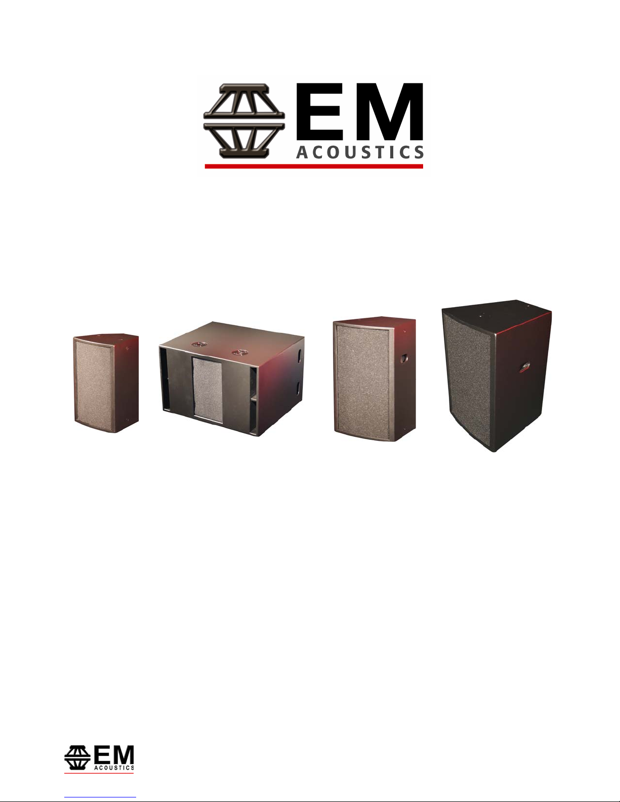
EMS-81/EMS-81i Loudspeaker
The EMS-81 is a versatile, full-range loudspeaker product designed for a wide variety of compact and discreet
sound reinforcement applications. It features a high-power 8” (203mm) vented LF driver and a 1” (25mm) exit HF
compression driver on a rotatable 90° x 60° waveguide. These components are matched by an internal UniPhase
crossover network for unprecedented sonic quality from a completely passive enclosure.
Through the use of the multi-angle enclosure, polemount socket, M10 and M6 rigging points and rotatable horn,
the EMS-81 can be used in a wide variety of applications from floor monitoring to permanent installations.
To rotate the HF waveguide:
1. Remove the front grille as described in the Maintenance section on Page 10 of this manual.
2. Using a 4mm Allen key, remove the four socket-head bolts retaining the HF waveguide in place.
3. Lift the waveguide up and rotate to the desired position – the wider exit of the waveguide shows the 90-
degree dispersion plane.
4. Reinstate the socket-head bolts and retighten. Avoid over-tightening as this may crack the waveguide.
5. Reinstate the grille as described in the Maintenance section on Page 10.
As with all EM Acoustics full-range products, no active controller or programmed EQ is required for correct
operation. For demanding applications, a 50Hz high pass filter is recommended to increase drive unit headroom
however this is not essential for normal operation.
The EMS-81i is the dedicated installation version of the EMS-81 with no handle or polemount, and with a single
NL4MP connector and a four-way barrier strip instead of two NL4MP connectors.
4
EMS Series User Manual
www.emacoustics.co.uk
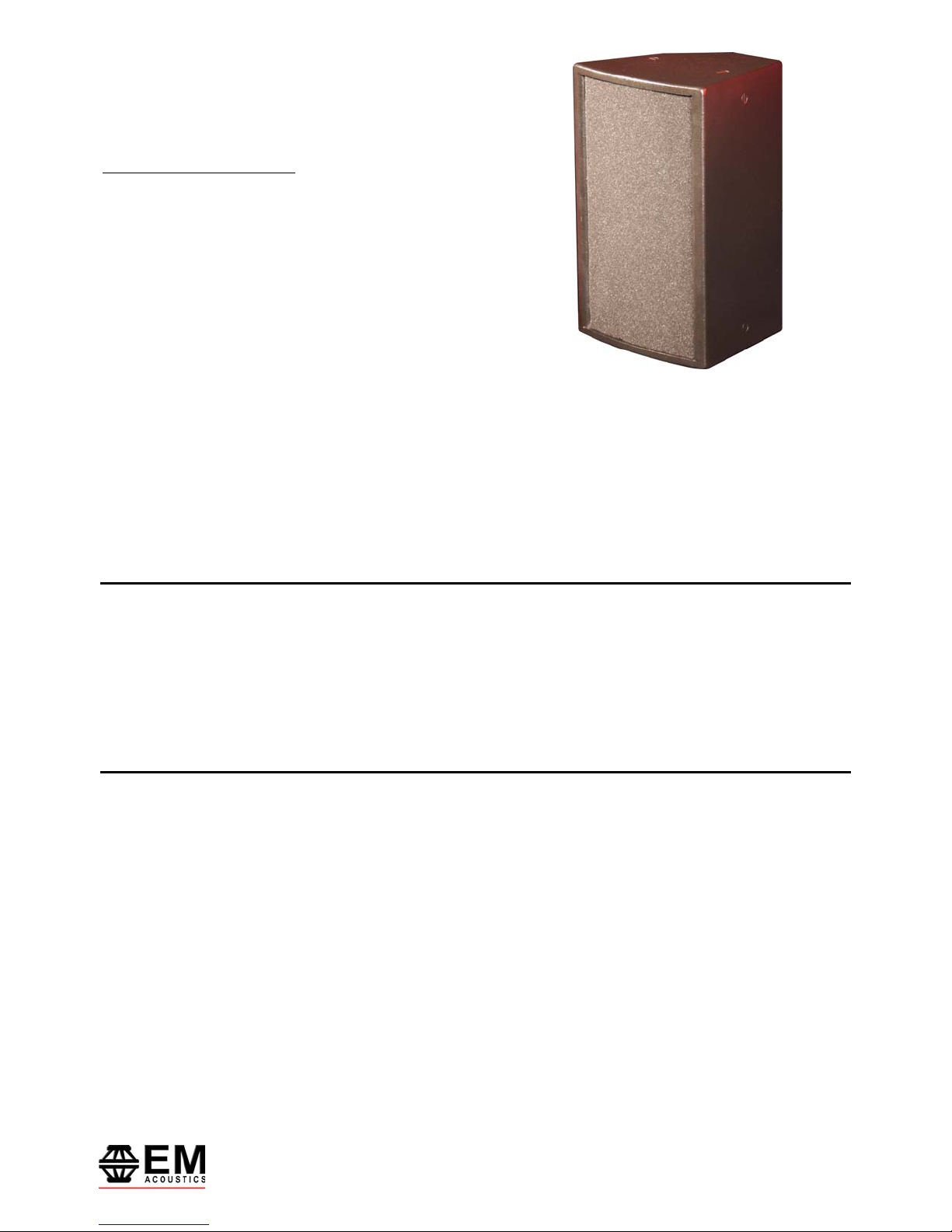
EMS-121/EMS-121w/EMS-121h/EMS-121i Loudspeaker
The EMS-121 is a versatile, full-range loudspeaker product designed for a wide variety of sound reinforcement
applications, where higher SPL and lower frequency response restrict the use of the EMS-81. It features a high-
power 12” (305mm) vented LF driver and a 1” (25mm) exit HF compression driver on either a 60°H x 40°V (EMS-
121) or 90°H x 40°V (EMS-121w) waveguide. These components are matched by an internal UniPhase crossover
network for unprecedented sonic quality from a truly passive enclosure.
The family of different formats for the EMS-121 allows a wide variety of applications to be covered – from stand-
mounting for public address or small live use through to horizontal installation in low-ceiling venues. M10 and M8
threaded fixings and an integral polemount socket are provided for ease of installation – both permanent and
temporary.
As with all EM Acoustics full-range products, no active controller or programmed EQ is required for correct
operation. For demanding applications, a 40Hz high pass filter is recommended to increase drive unit headroom
however this is not essential for normal operation.
The EMS-121i is the dedicated installation version of the EMS-121 with no handles or polemount, and with a single
NL4MPR connector and a four-way barrier strip instead of two NL4MPR connectors. The EMS-121h is a horizontal
mounting, permanent installation version for use in situations where ceiling height is critical.
5
EMS Series User Manual
www.emacoustics.co.uk
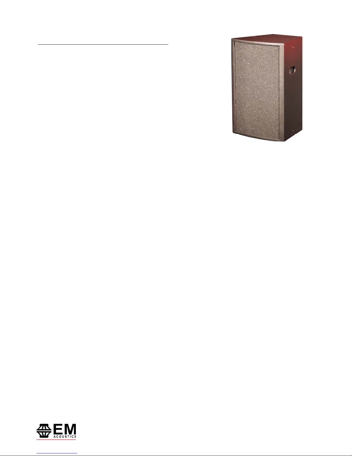
EMS-152/EMS-152w Loudspeaker
DA-1 Ready
The EMS-152 is a high power, medium-Q performance loudspeaker designed for a variety of applications within the
live and installation audio markets, where sonic performance and dispersion accuracy are of paramount
importance. The enclosure features a high-power 15” (381mm), 4” voice coil neodymium vented LF driver and a
4” aluminium diaphragm, 2” exit compression driver on either a 60°H x 40°V (EMS-152) or 90°H x 40°V (EMS-
152w) waveguide. Added to this is a specific cone profile to allow the dispersion of the 15” drive unit to match
that of the high frequency drive unit throughout the crossover region.
These precision components are matched by an internal UniPhase2 passive crossover network. This radical
approach to passive crossover technology achieves phenomenal frequency and phase responses without the need
for bi-amplification or external processing.
The two formats are intended to provide user-flexibility during system design – the EMS-152 is designed for array
construction whereas the EMS-152w can be used where wider coverage is required from a single enclosure – such
as centre fills or large format front fills.
Integral to the enclosure are four M10 flying points to allow suspension using a variety of different rigging
methods.
As with all other EM Acoustics fullrange products, no external processing or equalisation is required to allow the
loudspeaker to function correctly. However, for high SPL applications a high pass filter set above 40Hz is
recommended to remove unnecessary LF drive unit cone excursion. The EMS-152 can also accept the new DA-1
digital power amplifier module if required.
6
EMS Series User Manual
www.emacoustics.co.uk
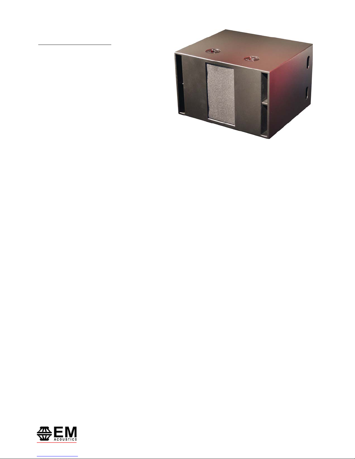
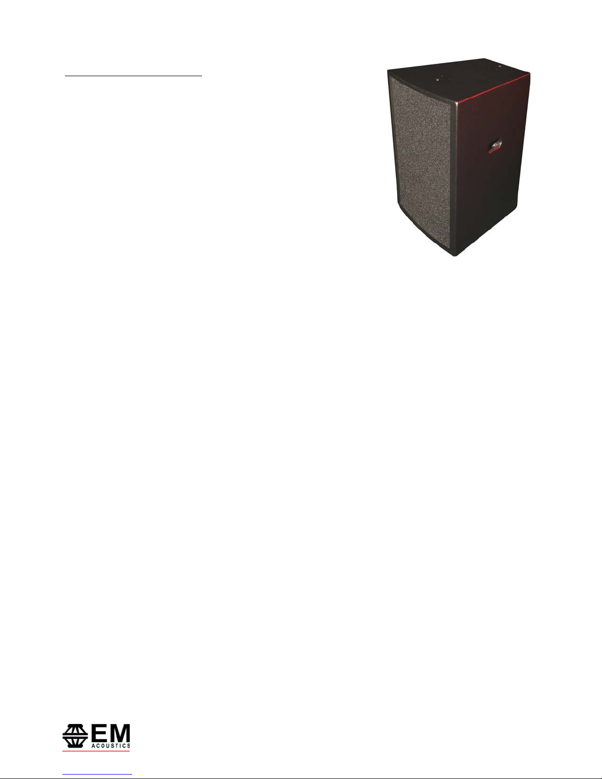
EMS-215/EMS-215i Subwoofer
DA-1 Ready
The EMS-215 is a compact, powerful subwoofer system designed to extend the low frequency performance of
EMS-81 and EMS-121 based systems. Through the use of a quasi-bandpass design, the enclosure size is kept to a
minimum to allow ease of use in installations where space is a premium.
It features a pair of high power 15” (381mm) LF drive units, each in their own vented chamber. Both drive units
then fire through a single exit, located behind the foam grille. For ease of transportation in portable applications,
the EMS-215 is fitted with four heavy duty castors and recessed handles. Three polemounts are also fitted to allow
the mounting of EMS-81 or EMS-121 enclosures above the subwoofer, in two different orientations.
An active crossover is required to set a low pass filter for correct operation, set at any point below 150Hz. A
24dB/Octave Linkwitz-Riley filter slope is recommended. For demanding applications, a 30Hz high pass filter is
recommended to increase drive unit headroom however this is not essential for normal operation.
The EMS-215i is the dedicated installation version of the EMS-215 with no handles, wheels or polemounts, and
with a single NL4MPR connector and a four-way barrier strip instead of two NL4MPR connectors. The EMS-215 can
also accept the new DA-1 digital power amplifier module if required.
7
EMS Series User Manual
www.emacoustics.co.uk

SYSTEM SET-UP
Safety Considerations
Loudspeaker systems are potentially dangerous objects if used incorrectly. Please ensure that you read this
section fully, and contact EM Acoustics or your local dealer should you be in any doubt over correct operation
procedures.
Professional loudspeaker systems are capable of producing damage-inducing sound pressure levels, and hence
care should be taken when setting your system up, particularly when it comes to loudspeaker placement within a
venue. Damage to the ear can result from levels above 90dB under prolonged exposure.
Stand Mounting
The EMS-81 and EMS-121 include 35mm polemount sockets for stand mounting. When mounting in this way,
please consider the following:
• Ensure your stand height is locked off and the tripod legs are positioned so as to be stable.
• Check the weight loading of your stands before attempting to mount the loudspeaker.
• Do not stack a second loudspeaker on top of the stand-mounted one.
• Ensure cables are run so as to leave enough slack to enable neat wiring, and thus reduce the risk of the
speaker being pulled over. Loose cables should be covered or taped down wherever possible to reduce trip
hazards.
• If stands are being used outdoors, it may be necessary to add ballast to the base of the stand to prevent it
toppling over.
• When using poles on top of subwoofer systems, please observe similar precautions.
Ground Stacking
• Ensure that the floor or stage surface can withstand the weight of the system.
• Wherever possible, avoid high stacks and use ratchet straps to secure loudspeakers together. Please also
remember that vibrations from subwoofer systems can shake other loudspeakers out of place, which may
present a toppling hazard. The use of ratchet straps and non-slip material is recommended to prevent this.
Rigging and Suspension
There are a variety of different methods for suspending your EMS-81 and EMS-121 enclosures – please see the
detailed section on Page 9 for further information.
WARNING: The overhead suspension of loudspeakers is a very serious issue with potentially lethal
consequences should anything go wrong. Rigging should only be carried out by experienced
8
EMS Series User Manual
www.emacoustics.co.uk
 Loading...