

Page 1
User’s Guide
IM845GV Motherboard
CCOONNTTEENNTTSS
Chapter 1 Motherboard Description
Motherboard Overview 1-3
Chapter 2 Using the BIOS Setup Program
About the Setup Program 2-1
Entering the Setup Program 2-2
BIOS Setup Program 2-4
Chapter 3 Installing Board Options
Before You Begin 3-1
Installing and Removing the Processor 3-2
Installing and Removing Memory Modules 3-5
Changing the Jumpers 3-7
Replacing the Battery 3-8
The Things to do in Post-installation 3-9
Appendix A Specifications
Specifications A-1
Rev. A
Page 2

Page 3

i
Battery Warning Instruction
Caution
If battery is incorrectly replaced there poses a danger of explosion. Replace battery only with the same or
equivalent type recommended by the manufacturer. Discard used batteries according to the
manufacturer’s instructions.
Attention
Il y a danger d‘explosion s‘il y a remplacement incorrect de la batterie. Remplacer uniquement avec une
batterie du méme type ou d‘un type recommandé par le constructeur. Mettre au rébut les batteries
usagées conformément aux instructions du fabricant.
Vorsicht
Explosionsgefahr bei unsachgemäß em Austausch der Batterie. Ersatz nur durch denselben oder einen
vom Hersteller empfohlenen ähnlichen Typ. Entsorgung gebraushter Batterien nach Angaben des
Herstellers.
Fuse Warning Instruction
Caution
For continued protection against risk of fire, replace only with same type and rating of fuse. Disconnect
input power before servicing. Only connect this equipment to an earthed socket outlet.
Vorsicht
Vor jeder service-arbeit netzstecker ziehen! Apparatet ma kun tilkobles jordet stikkontakt.
Attention
Debrancher avant d’ouvrir. Apparaten skall anslutas till jordat nätuttag.
Atencion
Desconecte fuerza electrica antes del servicio. Laite on liitettävä suojäkosketinistoraasian.
Safety Information
Page 4

ii
The information in this user’s guide is subject to change without notice.
eMachines, Inc. shall not be liable for technical or editorial errors or omissions contained herein; nor for
incidental or consequential damages resulting from the furnishing, performance, or use of this material.
eMachines, stylized “e” and figure logo are either trademarks or registered trademarks of eMachines, Inc.
in the United States and/or other countries.
All other product and brand names are trademarks of their respective owners.
©2003 eMachines, Inc. All rights reserved.
Before You Read
NOTE
Depending on the model, your computer’s components may vary and look slightly different than those
pictured.
Page 5

iii
CONTENTS
Chapter 1 Motherboard Description
Motherboard Overview
............................................................................................
1-3
Rear Panel Connectors
.....................................................................................
1-4
Chapter 2 Using the BIOS Setup Program
About the Setup Program
........................................................................................
2-1
Entering the Setup Program
....................................................................................
2-2
Help Window
...................................................................................................
2-3
BIOS Setup Program
...............................................................................................
2-4
Main Menu
.......................................................................................................
2-4
Advanced Menu
...............................................................................................
2-6
Security Menu
..................................................................................................
2-8
Power Menu
.....................................................................................................
2-9
Boot Menu
......................................................................................................
2-10
Exit Menu
.......................................................................................................
2-10
Page 6

iv
Motherboard Description
Chapter 3 Installing Board Options
Before You Begin
...................................................................................................
3-1
Installing and Removing the Processor
..................................................................
3-2
Installing the Processor
....................................................................................
3-2
Removing the Processor
..................................................................................
3-4
Installing and Removing Memory Modules
...........................................................
3-5
Installing a Memory Module
...........................................................................
3-6
Removing a Memory Module
.........................................................................
3-6
Changing the Jumpers
............................................................................................
3-7
Replacing the Battery
.............................................................................................
3-8
The Things to do in Post-installation
.....................................................................
3-9
Appendix A Specifications
Specifications
........................................................................................................
A-1
Page 7

1-1
Motherboard Description
Motherboard Description
Motherboard Description
This chapter describes the major features of your motherboard.
Your motherboard offers the following features:
●
Micro ATX form factor
●
Intel®Pentium®4 processor in the mPGA 478 pin package
●
Two DIMM sockets, expandable up to 2 GB using 1 GB DDR SDRAM modules
●
Two built-in Enhanced IDE controllers
●
Intel®82845GV Graphics Memory Controller Hub (GMCH)
●
Intel®82801DB I/O Controller Hub (ICH4)
●
Built-in high performance audio CODEC and PCI audio controller in Intel®82845GV GMCH
●
SMSC LPC47M192/LPC47M997 super I/O controller
●
Realtek RTL8101L LAN controller
●
Advanced Power Management (APM) and Advanced Configuration and Power Interface
(ACPI)
●
Three 32-bit PCI expansion card connectors
●
System BIOS and video BIOS shadow RAM
●
Plug-and-Play (PnP) BIOS feature
●
Password function by using BIOS
Page 8

1-2
Motherboard Description
●
Video memory using main memory
●
Two PS/2 style connectors for keyboard and mouse
●
One video connector
●
Four USB 2.0 connectors and one pinheader that supports two USB connectors
●
One LAN connector
●
One serial port connector
●
One parallel port connector
●
Three audio jacks
NOTE
The internal graphics device on Intel 82845GV supports Intel Dynamic Video Memory
Technology (D.V.M.T). D.V.M.T. dynamically responds to application requirements by
allocating the proper amount of display and texturing memory.
As your system has sharing memory architecture using the main memory for video memory,
the usable main memory size is less than real size when the computer is running.
Page 9
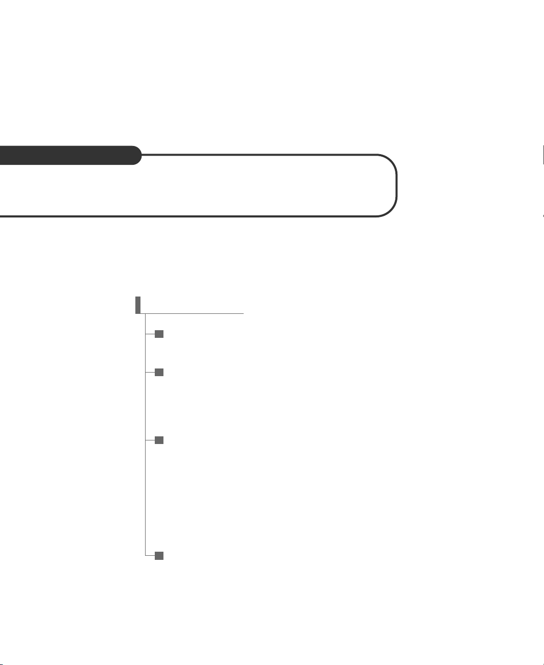
Back panel
I/O connectors
Front microphone and
headphone connector
CPU fan connector
Auxiliary 12V power
supply connector
Power supply connector
Video audio connector
CD audio connector
Intel 82845GV Graphics Memory
Controller Hub(GMCH)
mPGA478 socket
DIMM sockets
SMSC LPC47M192/
LPC47M997 super I/O
controller
Speaker
FDD connector
Secondary EIDE
connector
Primary EIDE
connector
Front panel connecter
Jumpers
Intel 82801DB I/O
controller Hub (ICH4)
FWH
(Firm Ware Hub)
PCI slots
Front USB connector
Battery
System fan connector
Realtek ALC202A
audio codec
Realtek RTL8101L
LAN controller
1-3
Motherboard Description
NOTE
The motherboard's components may vary and look slightly different.
Motherboard Overview
Page 10
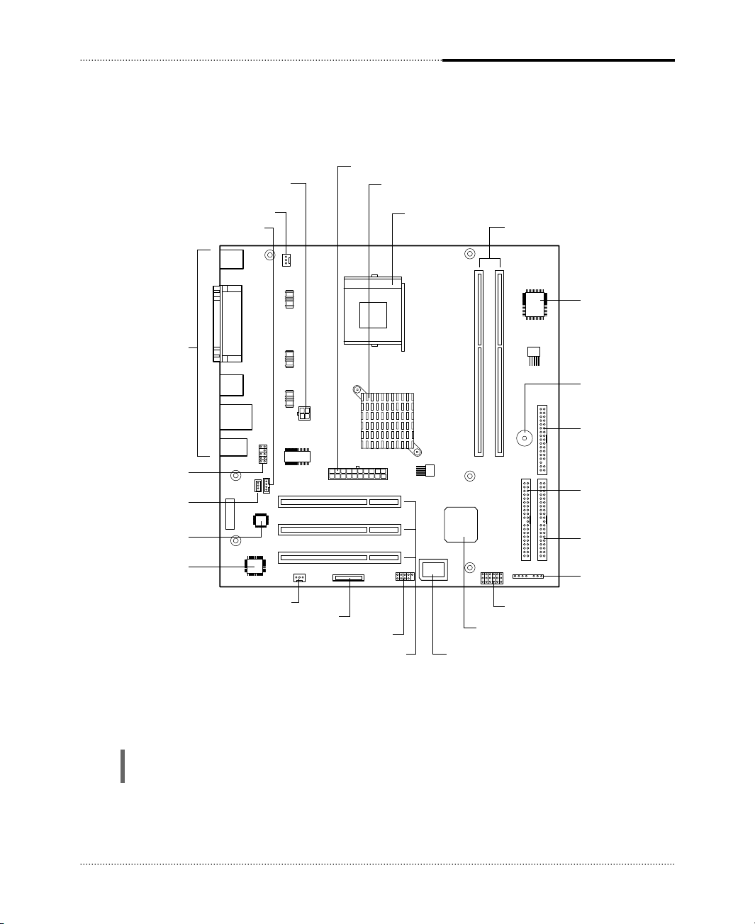
Serial port (COM1) connector
PS/2 mouse
connector
PS/2 keyboard
connector
USB connectors
Parallel port connector
Microphone jack
Line-in jack
Speaker jack
LAN connector
Video connector
USB connectors
1-4
Motherboard Description
Rear Panel Connectors
The motherboard has connectors for peripheral devices.
Page 11

2-1
Using the BIOS Setup Program
Using the BIOS Setup Program
Using the BIOS Setup Program
This chapter explains how to use the BIOS Setup program. You can use the Setup program to
change the computer’s configuration information and boot-up sequence, etc.
Your system uses a Phoenix BIOS, which is stored in flash memory on the motherboard. This
enables you to run the program at any time when you turn on or reset your computer.
The configuration you define through the Setup program is stored in a special area of memory
called CMOS RAM. The battery on the motherboard backs up this memory, so the memory is not
erased when you turn off or reset the computer. Whenever you reboot the computer, it checks the
settings, and if it discovers a difference between the information in the CMOS RAM and its actual
hardware configuration, it prompts you to run the Setup program.
About the Setup Program
Page 12

2-2
Using the BIOS Setup Program
To enter the Setup program, turn the computer on and press DEL as soon as you see the
“emachines” logo.
If you do not press the key quickly, the computer starts loading the operating system.
When you enter the Setup program, you will see the Setup menu. The legend bar at the bottom of
the menu displays function keys used in Setup.
The Setup program is for viewing and changing the BIOS settings for a computer. Setup is
accessed by pressing the <DEL> key after the Power-On Self Test (POST) begins and before the
operating system boot begins.
The next table shows the menus available from the menu bar at the top of the Setup screen.
Entering the Setup Program
NOTE
For reference purposes, write down the current Setup settings. When you make changes to the
settings, update this record.
NOTE
The actual menus displayed on your system may differ depending on the hardware and features
installed in your computer.
Setup Menu Screen Description
Main Allocates resources for hardware components.
Advanced Specifies advanced features available through the chipset.
Security Specifies passwords and security features.
Power Specifies power management features.
Boot Specifies boot options and power supply controls.
Exit Saves or discards changes to the Setup program options.
Page 13

2-3
Using the BIOS Setup Program
The next table shows the function keys available for menu screens.
Help Window
The field help window on the right of each menu displays the help text for the currently selected
field. Also, if pressing <F1> on any menu, you will see the General Help.
Setup Key Description
<F1> or <Alt-H> Brings up a help screen for the current item.
<Esc> Exits the menu.
<> or <> Selects a different menu screen.
<> or <> Moves cursor up or down.
<Home> or <End> Moves cursor to top or bottom of current menu.
<PgUp> or <PgDn> Moves cursor to previous or next page on scrollable menu.
<F5> or <-> Selects the previous value for a field.
<F6> or <+> or <Space> Selects the next value for a field.
<F9> Load the default configuration values for the current menu.
<F10> Save the current values and exit Setup.
<Enter> Executes command or selects the submenu.
Page 14

2-4
Using the BIOS Setup Program
BIOS Setup Program
Main Menu
This menu reports processor and memory information and is for configuring the system date,
system time, floppy options, and IDE devices.
Feature Options Description
System Time Hour, minute, and Specifies the current time.
second
System Date Month, day, and year Specifies the current date.
Language • English (US) You can select the display language for the BIOS.
• Français
• Español
Legacy Diskette A: • Disabled Specifies the capacity and physical size of diskette drive A.
• 360 KB, 5
1
/
4”
• 1.2 MB, 5
1
/
4”
• 720 KB, 3
1
/
2”
• 1.44/1.25 MB, 3
1
/
2”
• 2.88 MB, 3
1
/
2”
Primary IDE No options Reports type of connected IDE device. When selected,
Master, submenu displays the Primary IDE Master submenu.
Primary IDE No options Reports type of connected IDE device. When selected,
Slave, submenu displays the Primary IDE Slave submenu.
Secondary IDE No options Reports type of connected IDE device. When selected,
Master, submenu displays the Secondary IDE Master submenu.
Secondary IDE No options Reports type of connected IDE device. When selected,
Slave, submenu displays the Secondary IDE Slave submenu.
System Memory No options Displays the amount of system memory.
Extended Memory No options Displays the amount of Extended memory.
Page 15

2-5
Using the BIOS Setup Program
Feature Options Description
Type • Auto Auto automatically fills in the values for the cylinders, heads, and
sectors fields.
Multi-Sector No options Displays the number of sectors per block for transfers from the hard
Transfers drive to memory.
LBA Mode No options Displays the status of logical block addressing control.
Control
32 Bit I/O • Disabled Enables or disables 32 bit communication between CPU and IDE
• Enabled card. Requires PCI or local bus.
Transfer Mode No options Displays the method for transferring data between the hard drive
and system memory.
Ultra DMA Mode No options Displays the ultra DMA mode for the hard drive.
IDE Device Configuration Submenus
This submenu is for configuring IDE devices, including:
●
Primary IDE master/slave
●
Secondary IDE master/slave
Page 16

2-6
Using the BIOS Setup Program
Advanced Menu
This menu is for setting advanced features that are available through the chipset.
Feature Options Description
CPU Type No options Displays the processor type.
CPU Speed No options Displays the processor speed.
Cache Ram No options Displays the amount of cache RAM.
Plug & Play O/S • No If you select Yes, the BIOS configures Plug and Play devices when
• Yes your system has a Plug & Play operating system.
Reset • No Yes erases all configuration data in ESCD, which stores the
Configuration Data • Yes configuration settings for non-PnP plug-in devices. Select Yes when
required to restore the manufacturer’s defaults.
Primary Video • PCI This option lets you define the type of your video adapter you are
Adapter • Onboard using for your primary display.
Local Bus IDE • Disabled Allows you to set the built-in IDE controller you want to use.
adapter • Primary
• Secondary
• Both
Large Disk Access • Other Select DOS if you have DOS. Select Other if you have another
Mode • DOS operating system such as UNIX. A large disk is one that has more
than 1024 cylinders, more than 16 heads, or more than 63 tracks per
sector.
Legacy USB Support • Disabled Enables or disables the legacy USB.
• Enabled
Onboard LAN • Disabled Enables or Disables the onboard LAN. Select Disabled, if you
Control • Enabled don’t want use onboard LAN function.
Onboard LAN Boot • Disabled Use this item to enable and disable the booting from the
ROM • Enabled onboard LAN or a network add-in card with a remote boot
ROM installed.
I/O Device No options Configures I/O devices. When selected, displays the I/O Device
Configuration, Configuration submenu.
Submenu
Onboard Audio No options Configures onboard audio. When selected, displays the Onboard
Options, Submenu Audio Options submenu.
Hardware Monitor, No options Reports the speed of the CPU fan and system fan. When selected,
Submenu displays the Hardware Monitor submenu.
Page 17

2-7
Using the BIOS Setup Program
Feature Options Description
Serial port A: • Disabled Configures serial port.
• Enabled If you select Enabled, you must assign the address and interrupt.
Base I/O address • 3F8 Selects the base I/O address for serial port.
• 2F8
• 3E8
• 2E8
Interrupt • IRQ 3 Selects the interrupt for the serial port.
• IRQ 4
Parallel port • Disabled Configures the parallel port.
• Enabled
Mode •Bi-directional Selects the mode for the parallel port.
• EPP
• ECP
Base I/O address • 378 Selects the base I/O address for parallel port.
• 278
• 3BC
Interrupt • IRQ 5 Selects the interrupt for the parallel port.
• IRQ 7
DMA channel • DMA 1 Selects the DMA channel for the parallel port.
• DMA 3
I/O Device Configuration Submenu
This submenu is for configuring the I/O devices.
Feature Options Description
Audio codec • Disabled Select Disabled, if you don't want use AC’97 audio.
• Enabled
• Auto
Onboard Audio Options Submenu
This submenu is for configuring the onboard audio.
Page 18

2-8
Using the BIOS Setup Program
Feature Options Description
CPU Fan Speed No options Displays the CPU fan speed.
System Fan Speed No options Displays the system fan speed.
Feature Options Description
Set Supervisor Password can be up Specifies the supervisor password.
Password to seven alphanumeric
characters.
Set User Password Password can be up Specifies the user password.
to seven alphanumeric
characters.
Password On Boot • Disabled Enables password entry on boot.
• Enabled
Password set Supervisor User mode Password during Password to enter
mode boot the Setup Program
Neither Can change Can change all options None None
all options
Supervisor Can change N/A Supervisor Supervisor
only all options
Both Can change Can change a limited Supervisor or User Supervisor or User
all options number of options
Hardware Monitor Submenu
This submenu reports the speed of CPU fan and system fan.
Security Menu
This menu is for setting passwords and security features.
If you set both the Supervisor and User passwords, you must set the Supervisor password first.
Once both are set, you can enter either the Supervisor password or the User password to access the
Setup or the computer.
The table shows the effects of setting the Supervisor and User passwords.
NOTE
Be sure to remember the password you enter or write it down. You will not be able to access the
computer the next time you turn it on or run SETUP without the password.
Page 19

2-9
Using the BIOS Setup Program
Deleting or Changing a Password
If you want to delete the current password, follow these steps:
1. Press Enter at Set User Password or Set Supervisor Password from the Security menu.
2. Type the current password in “Enter Current Password” and press Enter.
3. Just press Enter in “Enter New Password” to delete your current password.
4. When you see “Confirm New Password”, press Enter again.
5. When you see the following message, press Enter.
Changes have been saved.
To change the current password, type your new password before pressing Enter on steps 3 and 4.
Feature Options Description
After AC Power • Stay Off Specifies how the computer responds to a power failure or when
Failure • Auto you connect the AC power cable to your computer. If you set it to
• Power On Stay Off, the computer keeps power off until power button pressed.
If you set it to Power On the computer restores power.
Power Menu
This menu is for setting power features.
Page 20

2-10
Using the BIOS Setup Program
Feature Options Description
Boot-time • Disabled Displays system summary screen during bootup.
Diagnostic Screen • Enabled
Quick Boot Mode • Enabled Enables the computer to boot without running certain POST
• Disabled
Boot Device Priority • No options Specifies the search order for the types of boot devices
Boot Menu
This menu is for setting the boot sequence.
Feature Description
Exit Saving Changes Exits and saves the changes in CMOS RAM.
Exit Discarding Changes Exits without saving any changes made in Setup.
Load Setup Defaults Loads the default values for all the Setup options.
Discard Changes Discards changes without exiting Setup. The option values (present when the
computer was turned on) are used.
Save Changes Saves the changes in CMOS RAM.
Exit Menu
This menu is for exiting the Setup program, saving changes, and loading and saving defaults.
Boot Device Priority Submenu
You can select the boot sequence from the available devices.
To specify boot sequence:
1. Select the boot device with <> or <>.
2. Press <+> to move the device up the list or <-> to move the device down the list.
Page 21

3-1
Installing Board Options
Installing Board Options
Installing Board Options
This chapter describes how to install board options in your computer. You can use these
instructions to install a variety of devices and board options. Although your board options may
look a bit different from the ones illustrated herein, you can install and remove it the same way.
Before You Begin
WARNINGS
The procedures in this chapter assume familiarity with the general terminology associated with
personal computers and with the safety practices and regulatory compliance required for using
and modifying electronic equipment.
Disconnect the computer from its power source and from any telecommunications links, networks,
or modems before performing any of the procedures described in this chapter. Failure to
disconnect power, telecommunications links, networks, or modems before you open the computer or
perform any procedures can result in personal injury or equipment damage. Some circuitry on the
motherboard can continue to operate even though the front panel power button is off.
CAUTION
Electrostatic discharge (ESD) can damage components. Perform the procedures described in this
chapter only at an ESD workstation. If such a station is not available, you can provide some ESD
protection by wearing an antistatic wrist strap and attaching it to a metal part of the computer
chassis.
Page 22

ZIF handle
Triangle mark
Blank corner
3-2
Installing Board Options
The processor that you install must be compatible with mPGA478 socket.
Installing and Removing the Processor
Installing the Processor
To install the processor, follow these steps:
1. See the illustration in “Motherboard Overview” in Chapter 1 for the location of the processor
socket.
2. Pull the ZIF handle sideways away from the socket then upward to 90-degree angles.
3. Locate the new processor you are installing over the socket so that the marked with triangle
corner on the processor can be aligned with the first blank corner on the socket. Then gently
push the processor straight into the socket until its pins are completely inserted into the holes of
the socket.
NOTE
According to processor type, your actual process may be slightly different from one described
below.
WARNING
A processor you plan to install should have a fan type heatsink attached to it to prevent
overheating. If there is no fan type heatsink, the processor may overheat and cause damage to both
the processor and motherboard.
Page 23

3-3
Installing Board Options
4. Press the ZIF handle back to close it.
5. Attach the heatsink to the processor socket.
6. Connect the fan connector cable from the CPU fan to the CPU fan connector on the
motherboard.
NOTE
Depending on the model, the heatsink may vary.
NOTE
If you install the processor chip in the wrong orientation, you may burn the chip and void your
warranty.
Page 24

3-4
Installing Board Options
Removing the Processor
To remove the processor, follow these steps:
1. Unplug the cable connector from the CPU fan connector on the motherboard.
2. Remove the heatsink by releasing both tabs on the heatsink that secure the heatsink to the
socket.
CPU fan connector
NOTE
Depending on the model, the heatsink may vary.
Page 25

3-5
Installing Board Options
3. Pull the ZIF handle sideways away from the socket then upward to 90-degree angles and
carefully pull the chip straight up from the socket.
4. Press the ZIF handle back to close it.
The motherboard has two dual inline memory module (DIMM) sockets. You can increase the
amount of memory in your computer up to 2 GB.
Each DIMM socket supports the following memory features:
●
184-pin 2.5 V DIMM with gold-plated contacts
●
200/266/333 MHz Non-ECC unbuffered DDR SDRAM
●
Single or double sided DIMM in the following sizes:
Installing and Removing Memory Modules
DIMM Size Non-ECC Configuration
64MB 8 Mbit × 64
128MB 16 Mbit × 64
256MB 32 Mbit × 64
512MB 64 Mbit × 64
1 GB 128 Mbit × 64
ZIF handle
Page 26

3-6
Installing Board Options
Installing a Memory Module
Follow these steps to install DIMMs:
1. Release the plastic retaining clips at each end of the socket by pressing the clips outward until
they snap open.
2. Orient a DIMM to the socket so the notch in the DIMM connector are aligned with the
crossbars in the socket.
3. Press the DIMM straight down until retaining tabs snap into place around the ends of the
DIMM.
Removing a Memory Module
To remove memory modules, press the retaining clips outward simultaneously until the DIMM
disengages from the socket and then carefully remove the DIMM from the socket.
Retaining clips
Crossbar
Notch
Page 27

3-7
Installing Board Options
The jumpers are small electrical connectors that control various circuits or functions in your
system. Jumpers are small blocks on a circuit board with two or more pins emerging from them.
To change a jumper setting, pull the plug off its pins and carefully fit it down onto the pins
indicated.
The jumper settings in your computer are preset at the factory; however, you can alter the functions
by changing the standard settings:
●
Enable or disable the password function.
●
Clear the CMOS settings.
●
Enable or disable the FDD write protect.
●
Enable or disable the CMOS Setup control.
Changing the Jumpers
NOTE
The jumper settings and their functions are inscribed on the motherboard or label attached in
your system chassis. If you want to see the label, you need to remove the cover of your system.
CAUTION
Do not change the jumpers with the power on. Always turn off the computer and unplug the power
cord from the computer before changing the jumpers.
Page 28

3-8
Installing Board Options
The 3 V, coin-cell CR2032-type battery on the mainboard provides power to the real-time clock
and CMOS RAM. It has an estimated lifetime of three years if the computer is turned off.
To replace the battery, follow these steps:
1. Turn off all peripheral devices connected to the computer and then turn off the computer.
2. Disconnect all cables from computer.
3. Remove the system cover.
4. Remove the battery out of its socket with your fingers.
6. Replace the system cover.
7. Connect all cables to your computer.
Replacing the Battery
Battery
Battery socket
5. Insert the new battery with the “+” side as shown below.
Page 29

3-9
Installing Board Options
After you install or remove board options, if necessary, be sure to run Setup program to update the
configuration of your system. See Chapter 2 for detail information.
If you installed a new optional equipment and Windows has installed in your system, you need to
have Windows detects it. See Windows manual and the manual that came with your optional
equipment for detail information.
The Things to do in Post-installation
Page 30

3-10
Installing Board Options
Blank
Page 31

Specifications
Specifications
A-1
Specifications
Feature Specifications
Form Factor Micro ATX
Processor • Intel
®
Pentium®4 processor
• 533 MHz and 400 MHz system bus with an integrated 256K L2 cache
Memory • Two 184-pin 2.5 V DIMM sockets
• Each slot supports up to 1 GB memory of 200/266/333 MHz Non-ECC
• Unbuffered DDR Synchronous DRAM (DDR SDRAM)
Video memory
• Use main memory (Intel Dynamic Video Memory Technology)
Main Chipset Intel®82845GV Graphics Memory Controller Hub (GMCH)
• Hyper-Threading technology support
• Processor/Host bus support
• Integrated DRAM controller
• Integrated graphics Controller (3D/2D graphics)
• Power management functions
Intel
®
82801DB I/O Controller Hub (ICH4)
• Support for the PCI interface
• Integrated IDE controller
• USB 2.0 and DMA controller
• Power management logic
• Real-time clock
• Support for AC ‘97 audio devices
Intel
®
82802AB Firmware Hub (FWH)
• Firmware Hub (FWH) interface
I/O Controller SMSC LPC47M192/LPC47M997 Super I/O Controller
• Floppy drive interface
• One multimode parallel port
• FIFO serial port
• Keyboard and mouse controller
NOTE
The processor depends on the model of computer you purchased.
NOTE
As your system has sharing memory architecture using the main memory for video
memory, the usable main memory size is less than real size when the computer is running
Page 32

A-2
Specifications
Feature Specifications
Built-in Audio Integrated Audio Controller in Intel
®
82801DB I/O Controller Hub (ICH4)
Controller • AC '97 2.2 Compliant
• AC '97 Link for Audio CODEC
• Separate Independent PCI Function for Audio
AD 1981A/Realtek ALC202A Audio Codec ‘97
• AC '97 2.2 compatible
• Industry Leading Mixed Signal Technology
• 16/18-bit stereo full-duplex Codec with independent and variable sampling
rate
• Four analog line-level stereo inputs for connection from LINE IN, CD, VIDEO
and AUX
• Advanced power management
Built-in LAN Realtek RTL8101L LAN controller
Controller • Integrated Fast Ethernet MAC, physical chip and transceiver in one chip
• Supports 10Mbps and 100Mbps N-way Auto-negotiation operation
• Supports 32-bit bus master data transfer
• Supports wake up LAN function
Expansion Slots • Three PCI slots
Other Features • Phoenix BIOS
• Plug and Play compatible
• Advanced Power Management (APM) and Advanced Configuration Power
Interface (ACPI)
Power Supply The power supply specifications are inscribed on the label that attached on
the power supply chassis in the system. To see the specifications of the power
supply, refer to the label. If you want to see the label, you need to remove the
cover of your system.
Environmental • Temperature
Requirement - Operation : +5
o
C to 35oC
- Storage : -10oC to 55oC
• Humidity
- Operation : 30% to 80% (No condensation)
- Storage : 20% to 90%
 Loading...