

eMachines EL1852G, EL1852 Service Manual

eMachines
EL1852 Service Guide
PRINTED IN TAIWAN

Revision History
Refer to the table below for changes made on this version of the EL1852 Desktop Computer Service Guide.
Date Chapter Updates
ii EL1852 Service Guide

Copyright
Copyright © 2011 by Acer Incorporated. All rights reserved. No part of this publication may be reproduced,
transmitted, transcribed, stored in a retrieval system, or translated into any language or computer language, in
any form or by any means, electronic, mechanical, magnetic, optical, chemical, manual or otherwise, without
the prior written permission of Acer Incorporated.
Disclaimer
The information in this guide is subject to change without notice.
Acer Incorporated makes no representations or warranties, either expressed or implied, with respect to the
contents hereof and specifically disclaims any warranties of merchantability or fitness for any particular
purpose. Any Acer Incorporated software described in this guide is sold or licensed "as is". Should the
programs prove defective following their purchase, the buyer (and not Acer Incorporated, its distributor, or its
dealer) assumes the entire cost of all necessary servicing, repair, and any incidental or consequential
damages resulting from any defect in the software.
Acer is a registered trademark of Acer Incorporated.
Other brand and product names are trademarks and/or registered trademarks of their respective holders.
EL1852 Service Guide iii

Conventions
The following textual conventions are used in this service guide.
SCREEN MESSAGES Denotes actual messages that appear on screen.
NOTE Gives additional information related to the current topic.
WARNING Alerts you to any physical risk or system damage that might result from
doing or not doing specific actions.
CAUTION Gives precautionary measures to avoid possible hardware or software
problems.
IMPORTANT Reminds you to do specific actions relevant to the accomplishment of
procedures.
iv EL1852 Service Guide

Service Guide Coverage
This Service Guide provides you with all technical information relating to the BASIC CONFIGURATION
decided for our "global" product offering. To better fit local market requirements and enhance product
competitiveness, your regional office MAY have decided to extend the functionality of a machine (e.g. add-on
card, modem, or extra memory capability). These LOCALIZED FEATURES will NOT be covered in this generic
service guide. In such cases, please contact your regional offices or the responsible personnel/channel to
provide you with further technical details.
FRU Information
Please note WHEN ORDERING FRU PARTS, that you should check the most up-to-date information available
on your regional web or channel. If, for whatever reason, a part number change is made, it will not be noted in
the printed service guide. For AUTHORIZED SERVICE PROVIDERS, your office may have a DIFFERENT
part number code to those given in the FRU list of this printed service guide. You MUST use the list provided
by your regional Acer office to order FRU parts for repair and service of customer machines.
EL1852 Service Guide v

vi EL1852 Service Guide

Table of Contents
Features and Specifications ................................................................... 1
Audio . . . . . . . . . . . . . . . . . . . . . . . . . . . . . . . . . . . . . . . . . . . . . . . . . . . . . . . . . . . . . . .2
I/O Ports and LED Indicators . . . . . . . . . . . . . . . . . . . . . . . . . . . . . . . . . . . . . . . . . . . . . .2
Physical Specifications . . . . . . . . . . . . . . . . . . . . . . . . . . . . . . . . . . . . . . . . . . . . . . . . . .3
Environmental Requirements . . . . . . . . . . . . . . . . . . . . . . . . . . . . . . . . . . . . . . . . . . . . .3
System Tour . . . . . . . . . . . . . . . . . . . . . . . . . . . . . . . . . . . . . . . . . . . . . . . . . . . . . . . . . .4
Front View . . . . . . . . . . . . . . . . . . . . . . . . . . . . . . . . . . . . . . . . . . . . . . . . . . .4
Rear Panel . . . . . . . . . . . . . . . . . . . . . . . . . . . . . . . . . . . . . . . . . . . . . . . . . . . . . 5
System Utilities ....................................................................................... 7
CMOS Setup Utility . . . . . . . . . . . . . . . . . . . . . . . . . . . . . . . . . . . . . . . . . . . . . . . . . . . 7
Accessing the Setup Utility . . . . . . . . . . . . . . . . . . . . . . . . . . . . . . . . . . . . . . . . . . .8
Navigating through the Setup Utility . . . . . . . . . . . . . . . . . . . . . . . . . . . . . . . . . . . 9
Setup Utility Menus . . . . . . . . . . . . . . . . . . . . . . . . . . . . . . . . . . . . . . . . . . . . . . . .9
System Disassembly ............................................................................. 23
Disassembly Requirements . . . . . . . . . . . . . . . . . . . . . . . . . . . . . . . . . . . . . . . . . . . . . .23
Pre-disassembly Procedure . . . . . . . . . . . . . . . . . . . . . . . . . . . . . . . . . . . . . . . . . . . . . .23
Disassembly Procedures . . . . . . . . . . . . . . . . . . . . . . . . . . . . . . . . . . . . . . . . . . . . . . . .24
Removing the Side Panel . . . . . . . . . . . . . . . . . . . . . . . . . . . . . . . . . . . . . . . . . . .24
Removing the Front Bezel . . . . . . . . . . . . . . . . . . . . . . . . . . . . . . . . . . . . . . . . . . .25
Removing the Heat Sink Fan Assembly . . . . . . . . . . . . . . . . . . . . . . . . . . . . . . . . .26
Removing the Processor . . . . . . . . . . . . . . . . . . . . . . . . . . . . . . . . . . . . . . . . . . . .27
Removing the HDD-ODD Bracket . . . . . . . . . . . . . . . . . . . . . . . . . . . . . . . . . . . . .28
Removing the Expansion Boards . . . . . . . . . . . . . . . . . . . . . . . . . . . . . . . . . . . . . .33
Removing the Memory Modules . . . . . . . . . . . . . . . . . . . . . . . . . . . . . . . . . . . . . 35
Removing the Power Supply Unit . . . . . . . . . . . . . . . . . . . . . . . . . . . . . . . . . . . . .35
Removing the Front I/O and Card Reader Assembly . . . . . . . . . . . . . . . . . . . . . .37
Removing the Mainboard . . . . . . . . . . . . . . . . . . . . . . . . . . . . . . . . . . . . . . . . . . .40
Hardware Diagnostic Procedure . . . . . . . . . . . . . . . . . . . . . . . . . . . . . . . . . . . . . . . . .41
System Check Procedures . . . . . . . . . . . . . . . . . . . . . . . . . . . . . . . . . . . . . . . . . . .41
Checkpoints . . . . . . . . . . . . . . . . . . . . . . . . . . . . . . . . . . . . . . . . . . . . . . . . . . . . .42
POST Error Indicators . . . . . . . . . . . . . . . . . . . . . . . . . . . . . . . . . . . . . . . . . . . . . .46
BIOS Recovery . . . . . . . . . . . . . . . . . . . . . . . . . . . . . . . . . . . . . . . . . . . . . . . . . . .58
BIOS Update . . . . . . . . . . . . . . . . . . . . . . . . . . . . . . . . . . . . . . . . . . . . . . . . . . . . .59
Clearning CMOS . . . . . . . . . . . . . . . . . . . . . . . . . . . . . . . . . . . . . . . . . . . . . . . . .63
System Architecture .............................................................................65
Block Diagram . . . . . . . . . . . . . . . . . . . . . . . . . . . . . . . . . . . . . . . . . . . . . . . . . . . . . . .65
Mainboard Layout . . . . . . . . . . . . . . . . . . . . . . . . . . . . . . . . . . . . . . . . . . . . . . . . . . . .66
Jumper Setting . . . . . . . . . . . . . . . . . . . . . . . . . . . . . . . . . . . . . . . . . . . . . . . . . . . . . . .67
Setting Jumper . . . . . . . . . . . . . . . . . . . . . . . . . . . . . . . . . . . . . . . . . . . . . . . . . . .68
Connecting Optional Devices . . . . . . . . . . . . . . . . . . . . . . . . . . . . . . . . . . . . . . . .69
Connecting Case Components . . . . . . . . . . . . . . . . . . . . . . . . . . . . . . . . . . . . . . .71
Field Replaceable Unit (FRU) List ......................................................... 73
Exploded Diagram . . . . . . . . . . . . . . . . . . . . . . . . . . . . . . . . . . . . . . . . . . . . . . . . . .74
EL1852 FRU List . . . . . . . . . . . . . . . . . . . . . . . . . . . . . . . . . . . . . . . . . . . . . . . . . . . . . .75
Technical Specifications ....................................................................... 86
Processor . . . . . . . . . . . . . . . . . . . . . . . . . . . . . . . . . . . . . . . . . . . . . . . . . . . . . . . . . . .86
Chipsets . . . . . . . . . . . . . . . . . . . . . . . . . . . . . . . . . . . . . . . . . . . . . . . . . . . . . . . . . . . 87
BIOS . . . . . . . . . . . . . . . . . . . . . . . . . . . . . . . . . . . . . . . . . . . . . . . . . . . . . . . . . . . . . . .87
EL1852 Service Guide vii

Table of Contents
Memory . . . . . . . . . . . . . . . . . . . . . . . . . . . . . . . . . . . . . . . . . . . . . . . . . . . . . . . . . . . .87
Hard Disk Drive . . . . . . . . . . . . . . . . . . . . . . . . . . . . . . . . . . . . . . . . . . . . . . . . . . . . . .88
Optical Disc Drive . . . . . . . . . . . . . . . . . . . . . . . . . . . . . . . . . . . . . . . . . . . . . . . . . . . . .88
Card Reader . . . . . . . . . . . . . . . . . . . . . . . . . . . . . . . . . . . . . . . . . . . . . . . . . . . . . . . 89
Gigabit Ethernet . . . . . . . . . . . . . . . . . . . . . . . . . . . . . . . . . . . . . . . . . . . . . . . . . . . . . .89
Audio . . . . . . . . . . . . . . . . . . . . . . . . . . . . . . . . . . . . . . . . . . . . . . . . . . . . . . . . . . . . . .89
Power Supply Unit . . . . . . . . . . . . . . . . . . . . . . . . . . . . . . . . . . . . . . . . . . . . . . . . . . . .89
Power Management . . . . . . . . . . . . . . . . . . . . . . . . . . . . . . . . . . . . . . . . . . . . . . . . . .90
Index ...................................................................................................... 91
viii EL1852 Service Guide

Chapter 1
Features and Specifications
This chapter lists the features and specifications of the EL1852 computer.
NOTE The items listed in this section are for reference only. The exact configuration of your PC depends
on the model purchased. Refer to the FRU list chapter on page 75 for a detailed list of models
supported by each hardware component.
System Features
Component Description
Operating system support • Microsoft Windows 7 Home Premium ×64
• Microsoft Windows 7 Home Basic ×32
• Microsoft Windows 7 Starter (×32 / ×64)
• Ubuntu X-windows version
• Linpus X-Windows
• FreeDos
Processor • LGA775 socket, 775 pin contacts
Core logic
Graphics controller
Memory • Two DIMM slots supporting 240-pin unbuffered DDR3 SDRAM modules
Expansion options • One PCI Express x16 slot
Connectivity • Wired LAN: Realtek RTL8111DL Gigabit Ethernet Controller
Hard disk drive (HDD) • One HDD bay suppporting 3.5-inch 25.4 mm SATA HDDs
Optical disc drive (ODD) • One ODD bay supporting 5.25-inch standard SATA ODD
• Supports the following multi-core Intel® processors:
– Intel® Core™ 2 Quad Q9550s, Q9400s and Q8400s Series
– Intel® Core™ 2 Duo E8600, E8500 and E8400 Series
– Intel® Core™ 2 Duo E7600 and E7500 Series
– Intel® Pentium® Dual-Core E6800, E6700, E5800 and E5700 Series
– Intel® Celeron® Dual core E3500 and E3400 Series, and Celeron 450
• North bridge: Intel® G41 Express Chipset
• South bridge: Intel® 82801GB I/O Controller Hub (ICH7)
Integrated in the Intel® G41 Express Chipset
• Data rate supported: 1066/1333 MT/s
• Maximum memory: 4 GB (using two 2 GB modules)
• One PCI Express x1 slot
• WLAN option: 802.11 b/g/n wireless network adapter
• Support SATA HDD in 160 – 1500 GB capacities
• Supports DVD-R/RW drive or DVD-Super Multi double-layer drive
EL1852 Service Guide 1

Component Description
Card reader (optional) • Multi-in-1 card reader
• The following memory cards are supported:
– Memory Stick (MS)
– xD-Picture Card (xD)
– Secure Digital (SD), MultiMediaCard (MMC), Reduced-Size
MultiMediaCard (RS-MMC)
– CompactFlash (CF) Types I and II
– Memory Stick PRO (MS PRO)
Power supply 220 W power supply unit (non-PFC 110V and 220V with select switch;
Active PFC 220V)
Antivirus software Symantec NTI 2009
System BIOS • AMI BIOS with 8 MB SPI ROM
• Supports ACPI revision 2.0 standard
• Supports Plug and Play, STR(S3)/STD(S4), hardware monitor, Multi Boot,
and DMI protocols
Power management • ACPI 2.0 or 1.0b (Advanced Configuration Power Interface) standard
• S0, S1, S2 and S5 sleep states support
• On-board device power management support
• On-board device configuration support
Audio
Item Description
Audio codec • Realtek ALC662 5.1 Channel High Definition Audio Codec
Audio jacks • Front panel: Headphone and microphone jacks
• Rear panel: Microphone, line-out, and line-in jacks
I/O Ports and LED Indicators
Component Description
I/O ports • Front panel
– USB ports (two)
– Headphone jack
– Microphone jack
– Card reader
• Rear panel
– PS/2 keyboard and mouse ports
– External display (VGA) port
– USB ports (two)
– Ethernet jack (RJ45)
– Microphone, line-out, and line-in jacks
– Kensington lock
– Key lock
LED indicators • Power LED
• Power button
2 EL1852 Service Guide

Physical Specifications
Aspect Description
Chassis dimension (W × D × H) 100 mm (W) X 361.8 mm (D) x 265 mm (H)
System weight 5.382 Kg.
Mainboard form factor microATX (µATX)
Mainboard dimensions (W × H) 244 × 200 mm
Environmental Requirements
Aspect Description
Operating temperature 5 to 35 °C (41 to 95 °F)
Operating humidity 15% to 80% RH non-condensing
EL1852 Service Guide 3
System Tour
The pictures and tables in this section illustrate the physical outlook of the computer.
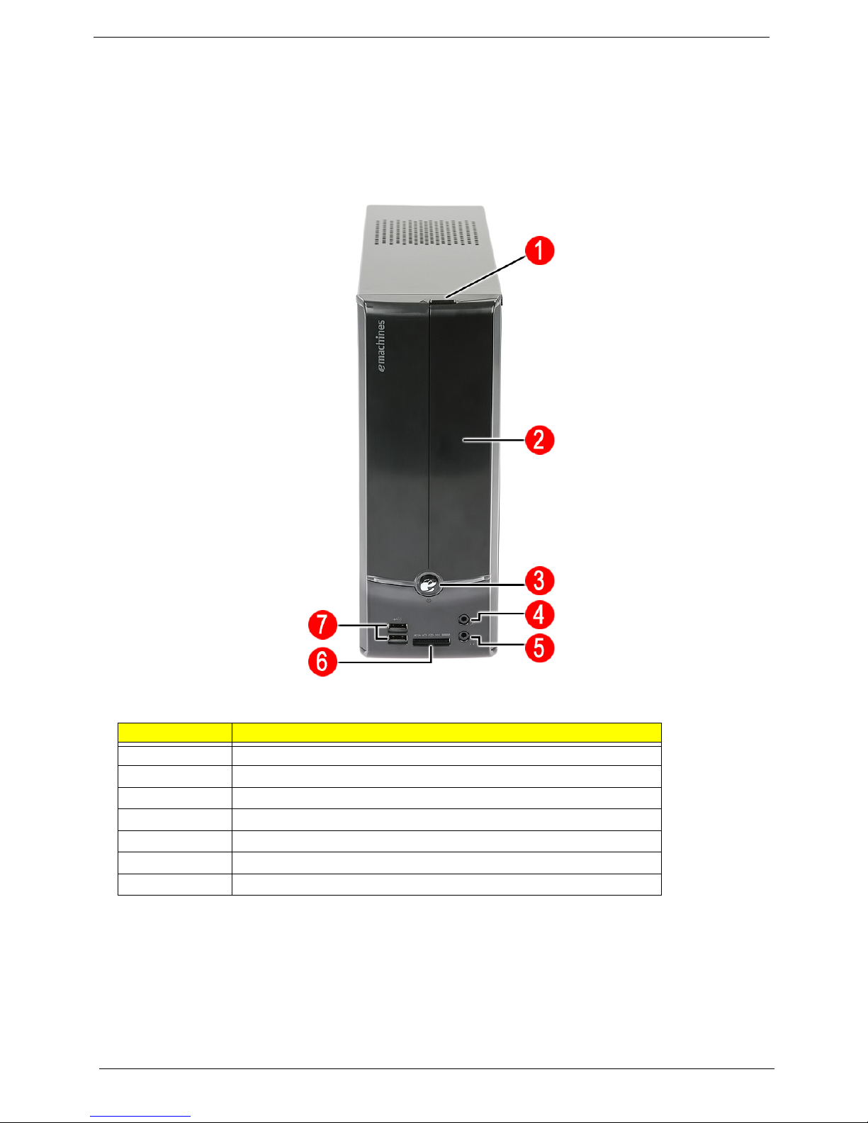
Front View
No. Component
1 Optical drive eject button
2 Optical drive cover
3 Power button/indicator
4 Microphone-in jack
5 Headphone jack
6 Multi-in-1 card reader
7 USB 2.0 ports
4 EL1852 Service Guide
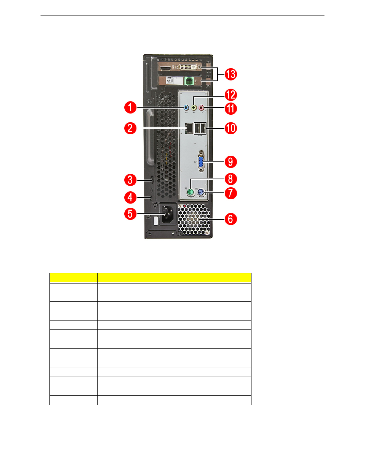
Rear Panel
No. Component
1 Line-in jack
2 LAN connector
3 Key lock
4 Kensington lock
5 Power connector
6 Fan aperture
7 PS/2 keyboard connector
8 PS/2 mouse connector
9 Monitor port
10
11
12 Line-out jack
13 Expansion slots
NOTE The I/O ports on the upper chassis area are additional items made possible with the installation of
an expansion card option.
USB 2.0 ports
Microphone jack
EL1852 Service Guide 5

6 EL1852 Service Guide

Chapter 2
System Utilities
CMOS Setup Utility
CMOS Setup Utility is a hardware configuration program built into the system ROM. Since most systems are
already properly configured and optimized, there is normally no need to run this utility.
You will need to run this utility under the following conditions:
• When changing the system configuration including:
• Setting the system time and date
• Configuring the system drives and peripherals
• Specifying the boot device sequence
• Configuring the power management modes
• Setting up system passwords or making other changes to the security setup
• When trying to resolve IRQ conflicts
• When a configuration error is detected by the system and you are prompted ("Run Setup" message) to
make changes to the BIOS settings.
The Setup Utility loads the configuration values in a battery-backed nonvolatile memory called CMOS RAM.
This memory area is not part of the system RAM, which allows configuration data to be retained when power is
turned off. The values take effect when the system is booted. POST uses these values to configure the
hardware. If the values and the actual hardware do not agree, POST generates an error message. You must
run this utility to change the hardware settings from the default or current configuration.
IMPORTANT If you repeatedly receive “Run Setup” messages, the RTC battery located on the mainboard
(RTC1) may be defective. In this case, the system cannot retain configuration values in
CMOS. Replace the RTC battery with a new one.
NOTE For ease of reading, CMOS Setup Utility will be simply referred to as “Setup” or “Setup Utility” in this
Service Guide.
EL1358 Service Guide 7
Accessing the Setup Utility
1. Turn on the server and the monitor.
If the server is already turned on, close all open applications, then restart the server.
2. During POST, press Delete.
If you fail to press Delete before POST is completed, you will need to restart the server.
Use the Up/Down/Left/Right arrow keys to move between the menu options, then press Enter to execute that
option.
Some options lead to pop-up dialog boxes that prompt you to verify that you wish to execute that option. Other
options lead to dialog boxes that prompt you for information.
Some options (marked with a ) lead to submenus that enable you to change the values for the option. Use
the Up/Down/Left/Right arrow keys to scroll through the items in the submenu
8 EL1358 Service Guide
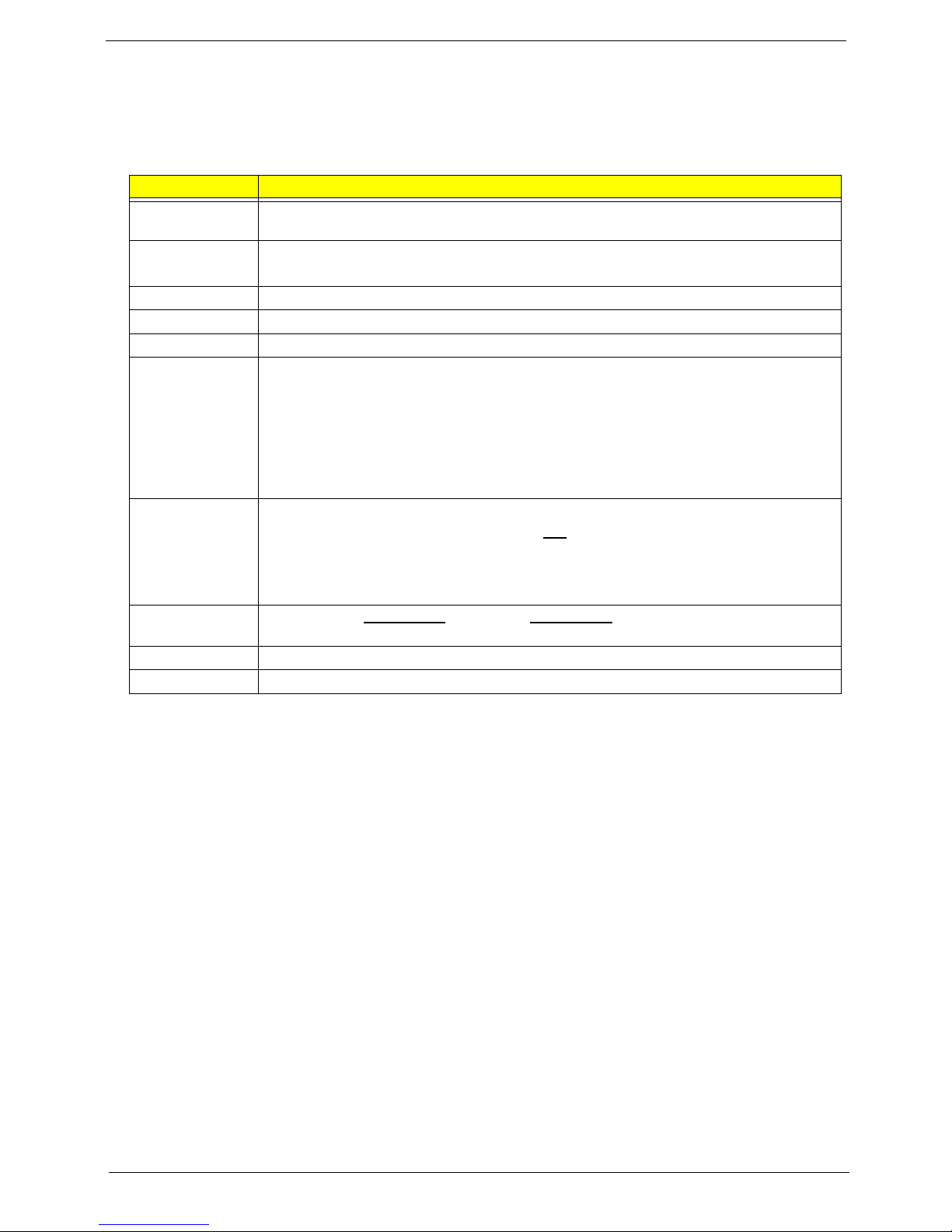
Navigating through the Setup Utility
Use the keys listed in the legend bar on the bottom of the Setup screen to work your way through the various
menu and submenu screens of the Setup Utility. The table below lists these legend keys and their respective
functions.
Key Function
Up/Down/Left/
Right arrow keys
Enter • To open the page for the currently selected menu/submenu
PgUp and PgDn Move the cursor to the previous and next page of a multipage menu.
Home Move the cursor to the first page of a multipage menu.
End Move the cursor to the last page of a multipage menu.
+ and -
Esc If you press this key:
F1 To bring up the General Help window. The General Help window describes other Setup
F9 Press to load default system values.
F10 Press to save changes and close the Setup Utility.
Move the cursor to the menu/field you want.The currently selected field will be highlighted.
• To apply a field value.
To select a value for the currently selected field (only if it is user-configurable). Press these
keys repeatedly to display all possible entries. A parameter that is enclosed in square
brackets [ ] is user-configurable. Grayed-out parameters are not user-configurable for one
of the following reasons:
• The field value is auto-configured or auto-detected.·
• The field value is informational only.
• The field is password-protected.
• On one of the primary menu screens, the Exit menu displays.
• On a submenu screen, the previous screen displays.
• When you are making selections from a pop-up menu, closes the pop-up without making
a selection.
navigation keys that are not displayed on the legend bar.
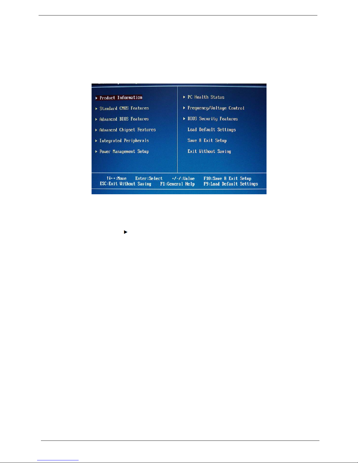
Setup Utility Menus
The Setup Utility has twelve menus for configuring the various system functions. These include:
• Product Information
• Standard CMOS Features
• Advanced BIOS Features
• Advanced Chipset Features
• Integrated Peripherals
• Power Management Setup
NOTES • The screenshots used in this section are for illustration only. The values displayed may not be
the same as those in your computer.
• In the descriptive tables following each of the menu screen illustrations, settings in boldface are
the default and suggested settings.
• PC Health Status
• Frequency/Voltage Control
• BIOS Security Features
• Load Default Settings
• Save & Exit Setup
• Exit Without Saving
EL1358 Service Guide 9
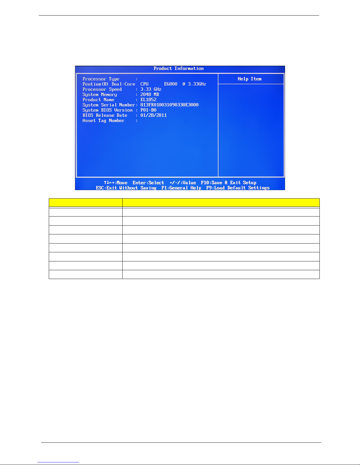
Product Information
The Product Information menu displays basic information about the system. These entries are for your
reference only and are not user-configurable.
Parameter Description
Processor Type Type of processor installed on the system
Processor Speed Speed of the processor installed on the system
System Memory Size of system memory detected during boot-up
Product Name Official model name of the computer.
System Serial Number System serial number.
System BIOS Version Current system BIOS version
BIOS Release Date Date when the CMOS setup utility was released.
Asset Tag Number System asset tag number
10 EL1358 Service Guide
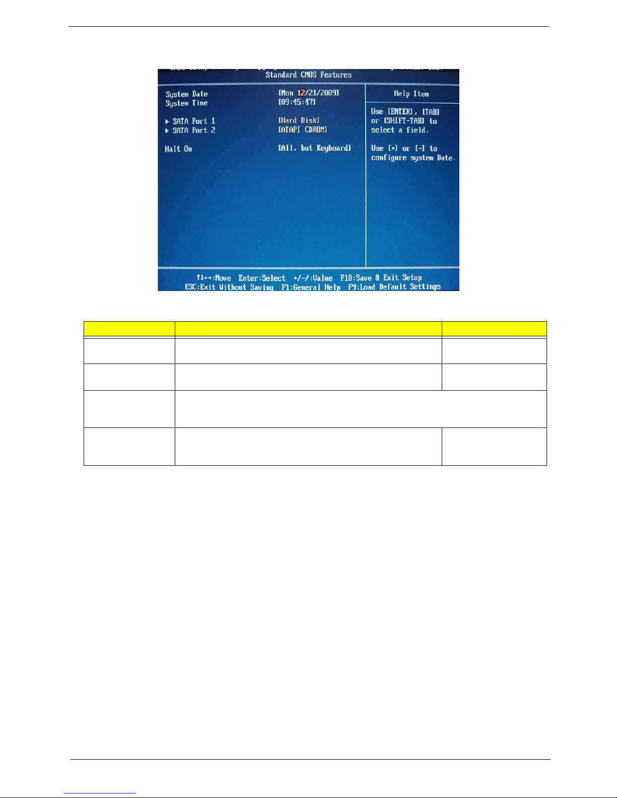
Standard CMOS Features
Field Description Value
System Date Sets the system date. MM/DD/YYYY
(month/day/year)
System Time Sets the system time. HH:MM:SS
(hour:minute:second)
SATA Port 1–2 Your Aspire computer supports two SATA channels, each channel allows one SATA
device to be installed. Press Enter to display the individual configuration screen of
installed SATA drive(s).
Halt On Determines whether the system will stop for an error during the
POST.
All, But Keyboard
No Errors
All Errors
EL1358 Service Guide 11
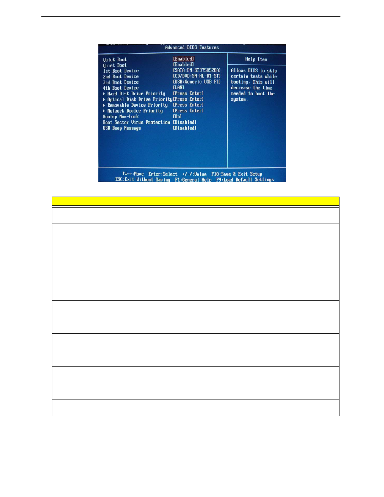
Advanced BIOS Feature
Field Description Val ue
Quick Boot When enabled, the system starts up more quickly be elimination
some of the POST routines.
Quiet Boot When enabled, BIOS will show a full screen logo when booting; if
disabled, BIOS will show the diagnostic POST screen when
booting.
1st/2nd/3rd/4th Boot
Device
Hard Disk Drive
Priority
Optical Disk Drive
Priority
Removable Device
Priority
Network Device
Priority
Bootup Num-Lock If you set this item to On, the keyboard Num Lock key will be active
Boot Sector Virus
Protection
USB Beep Message Select whether to allow the BIOS to emit error beeps or display
Displays the device assigned to the specified boot sequence. The Setup Utility attempts to
boot the operating system in this order. By default, the computer searches for boot
devices in the following order:
• Hard disk
• Optical drive (CD/DVD)
• Removable device
• Network boot (LAN)
Press Enter to specify the boot device priority sequence for the installed hard drive(s).
Press Enter to specify the boot device priority sequence for the installed optical drive.
Press Enter to specify the boot device priority sequence for removable drives.
Press Enter to specify the boot device priority sequence foe available network drives.
when the computer boots up.
If set to Disabled, when anything attempts to access the boot sector
or hard disk partition table, there will be no warning message.
error messages during USB device enumeration.
Enabled
Disabled
Enabled
Disabled
On
Off
Enabled
Disabled
Enabled
Disabled
12 EL1358 Service Guide
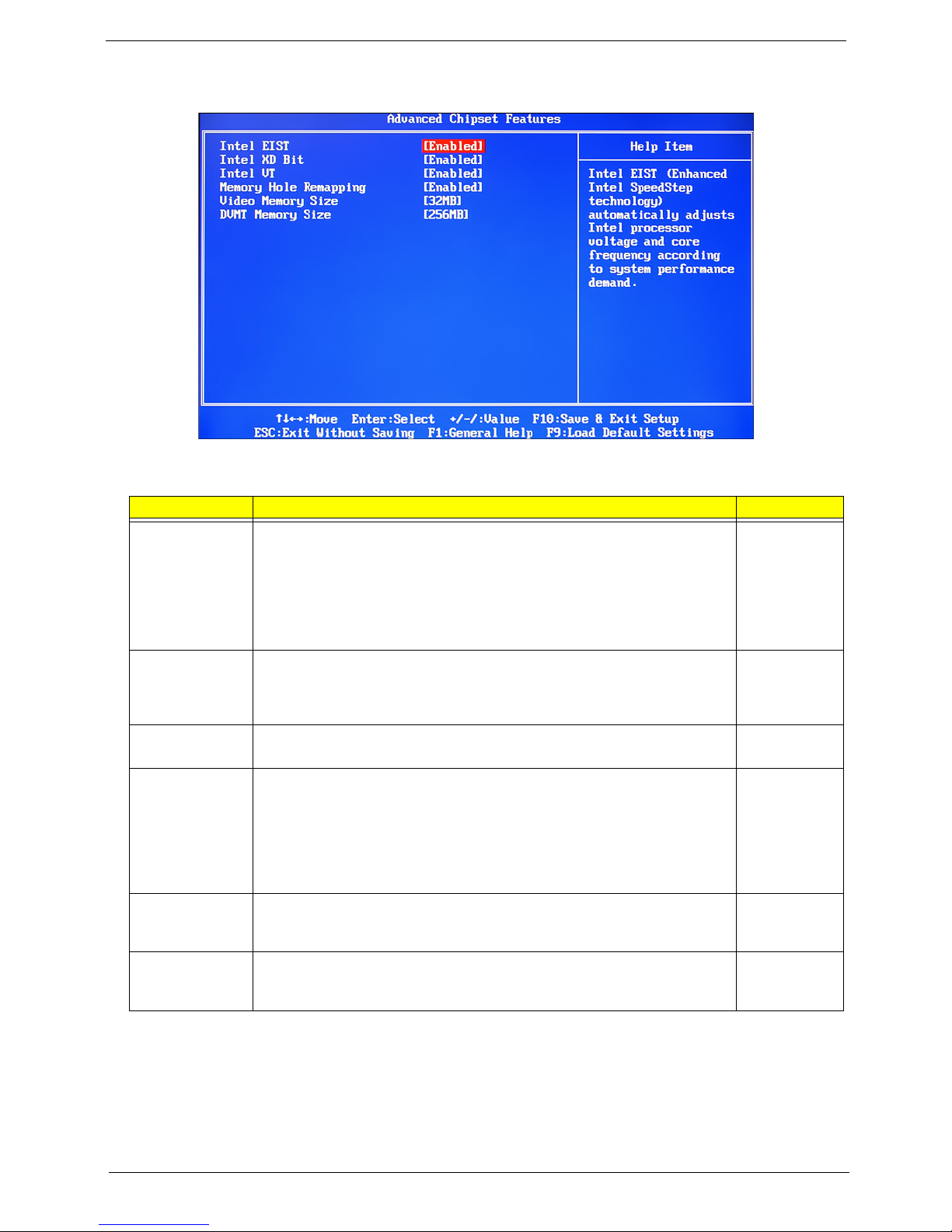
Advanced Chipset Features
Field Description Value
Intel EIST Select whether to enable the Enhanced Intel SpeedStep Technology. EIST
allows a compliant OS to dynamically adjust the processor voltage and core
frequency based on system usage. This can result in decreased average
power consumption and decreased average heat production.
Note: After enabling EIST in BIOS Setup, you need to enable it on your
operating system as well. Consult your OS documentation for related
instructions.
Intel XD Bit Select whether to enable the Intel Execute Disable Bit Technology. XD Bit is
a hardware-based security feature that can reduce exposure to viruses and
malicious-code attacks and prevent harmful software from executing and
propagating on the computer or network.
Intel VT Select whether to enable the Intel Virtualization Technology. VT allows a
single platform to run multiple operating systems in independent partitions.
Memory Hole
Remapping
Video Memory
Size
DVMT Memory
Size
When enabled, some or all of the memory between the 2 GB and 4 GB limits to
addresses above 4
hole which is a limitation of 32-bit hardware and 32-bit operating systems that
causes a computer to appear to have less memory available than is physically
installed.
GB. This is a workaround for the PCI hole or PCI memory
Note: This feature is useful for systems running on 64-bit OS and those 32-bit
systems that support the Physical Address Extension method.
Select the amount of system memory used by the internal graphics device.
This setting is only available for WinXp.
Enabled
Disabled
Enabled
Disabled
Enabled
Disabled
Enabled
Disabled
32MB
64MB
128MB
256MB
128MB
Maximum
EL1358 Service Guide 13
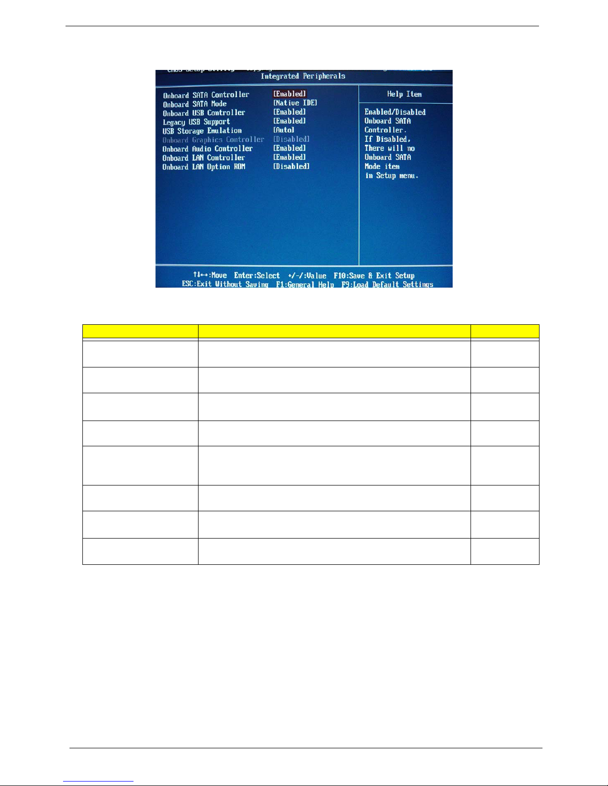
Integrated Peripherals
Field Description Value
Onboard SATA Controller
Onboard SATA Mode Select an operating mode for the onboard SATA. RAID
Onboard USB Controller Enables or disables the onboard USB controller.
Legacy USB Support Enables or disables support for legacy USB devices.
USB Storage Emulation If Auto, USB device equal or less than 2GB will be emulated as
Onboard Audio Controller Enables or disables the onboard audio controller.
Onboard LAN Controller Enables or disables the onboard LAN controller.
Onboard LAN Option ROM Enables or disables the load of embedded option ROM for onboard
Enables or disables the onboard SATA controller.
Floppy and remaining as harddrive. Forced FDD option can be
used to force a HDD formatted drive to boot as FDD (Ex.ZIP drive).
network controller.
Enabled
Disabled
Native IDE
Enabled
Disabled
Enabled
Disabled
Auto
Floppy
Hard Disk
Enabled
Disabled
Enabled
Disabled
Enabled
Disabled
14 EL1358 Service Guide
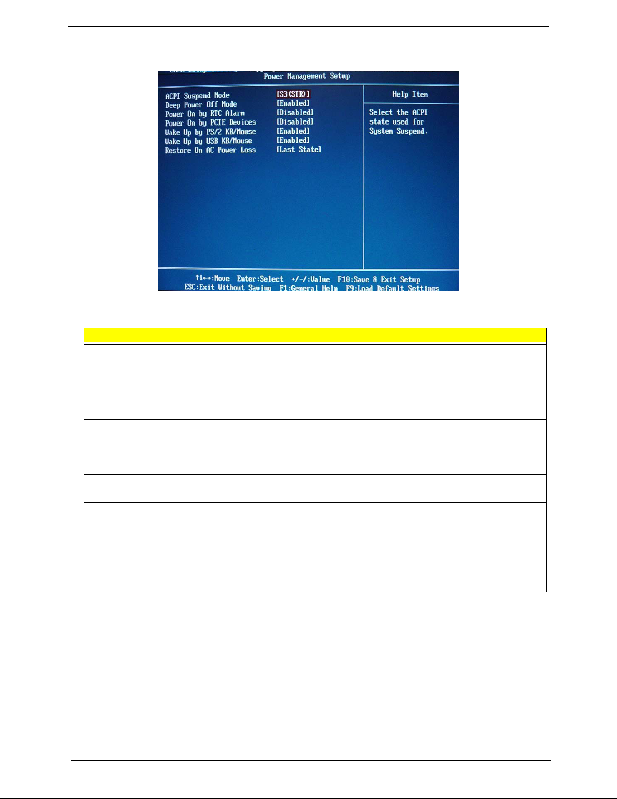
Power Management Setup
Field Description Value
ACPI Suspend Mode Use this item to define how your system suspends. Default value is
S3 (STR), the suspend mode is suspend to RAM, i.e., the system
shuts down with the exception of a refresh current to the system
memory.
Deep power off mode Enables or disables compliance to the Energy-using Products Lot 6
Directives (EuP Lot 6).
Power On by RTC Alarm Enables or disables the system to wake up from a power-saving
mode when an RTC alarm occurs.
Power On by PCIE Devices Enables or disables the system to wake up from a power-saving
mode when an event occurs on an installed PCI Express device.
Wake Up by PS/2 KB/
Mouse
Wake Up by USB KB/Mouse Enables or disables the system to wake up from a power-saving
Restore On AC Power Loss Select the power state when an AC power loss occurs.
Enables or disables the system to wake up from a power-saving
mode when a PS/2 keyboard or mouse is used.
mode when a USB keyboard or mouse is used.
• Off - The computer remains off until the power button is pressed.
• Last State - The computer reverts to the last power state before
the power loss occurred.
• On - The computer switches back on after the AC power loss.
S3 (STR)
S1 (POS)
Enabled
Disabled
Enabled
Disabled
Enabled
Disabled
Enabled
Disabled
Enabled
Disabled
Power Off
Power On
Last State
EL1358 Service Guide 15
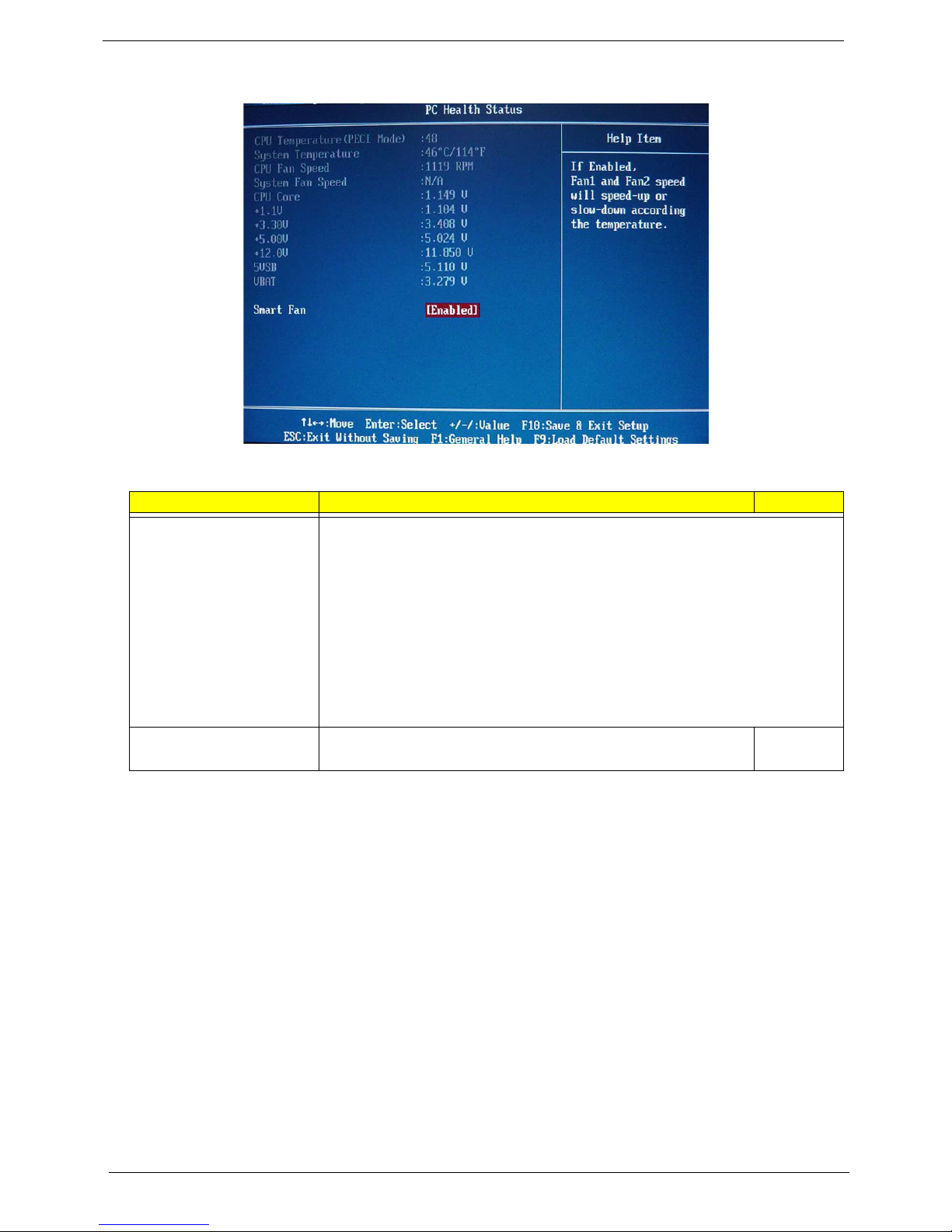
PC Health Status
Field Description Value
CPU Temperature
(PECI Mode)
System Temperature
CPU Fan Speed
System Fan Speed
CPU Core
+1.1V
+3.30V
+5.00V
+12.0V
5VSB
VBAT
Smart Fan When enabled, fan speed will speed up or slow down depending on
These items lets you monitor the parameters for critical voltages, temperatures and
fan speeds.
the system temperature.
Enabled
Disabled
16 EL1358 Service Guide
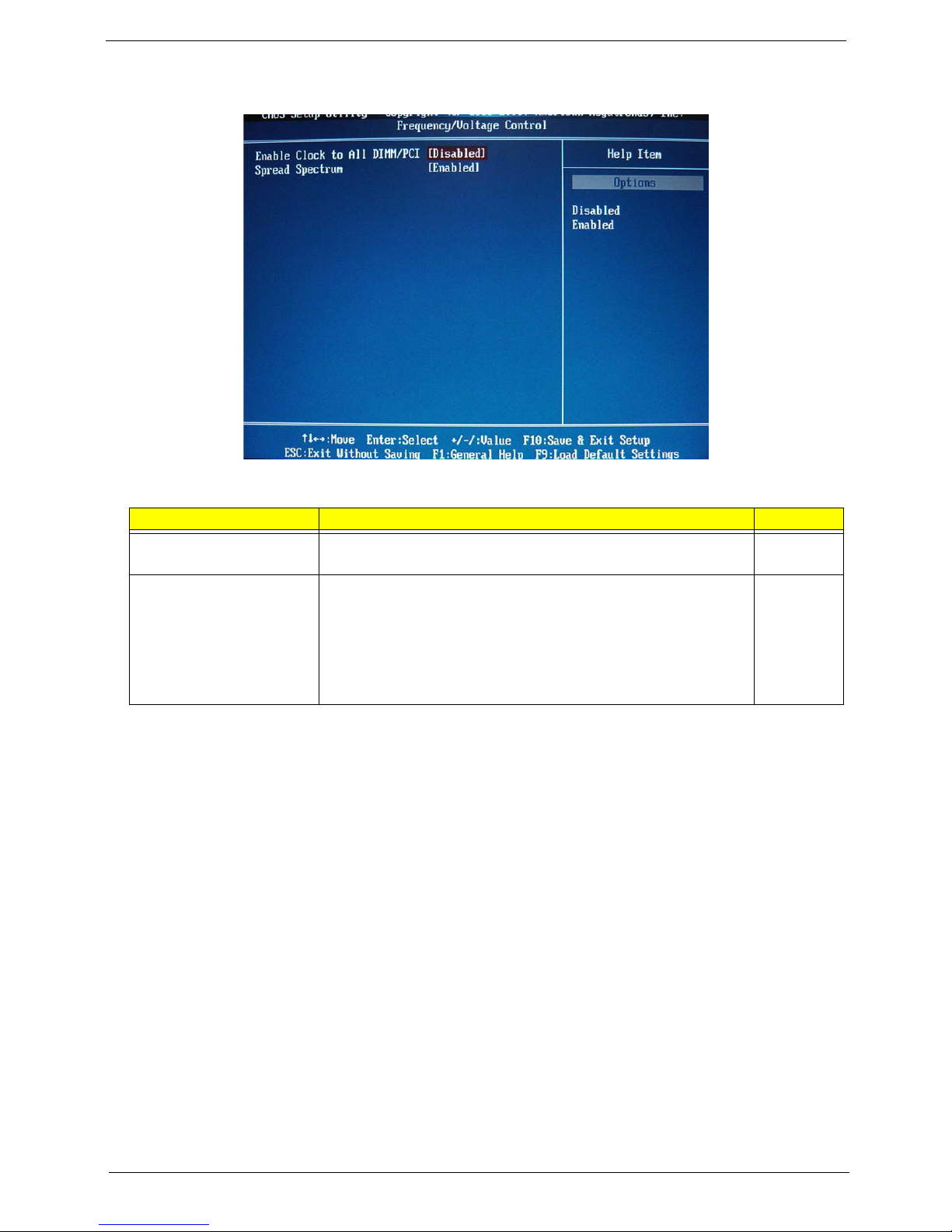
Frequency/Voltage Control
Field Description Value
Enable Clock to All DIMM/
PCI
Spread Spectrum When the mainboard's clock generator pulses, the extreme values of
When enabled, clock signals will be sent to the PCI and memory slots
regardless of whether the slot is occupied or not.
the pulses creates EMI (electromagnetic interference). Set this field
to Enabled to reduce this EMI level. This reduces interference
problems with other electronics in the area.
Note: Remember to disable the Spread Spectrum feature if you are
overclocking. A slight jitter can introduce a temporary boost in clock
speed causing the overclocked processor to lock up.
Enabled
Disabled
Enabled
Disabled
EL1358 Service Guide 17
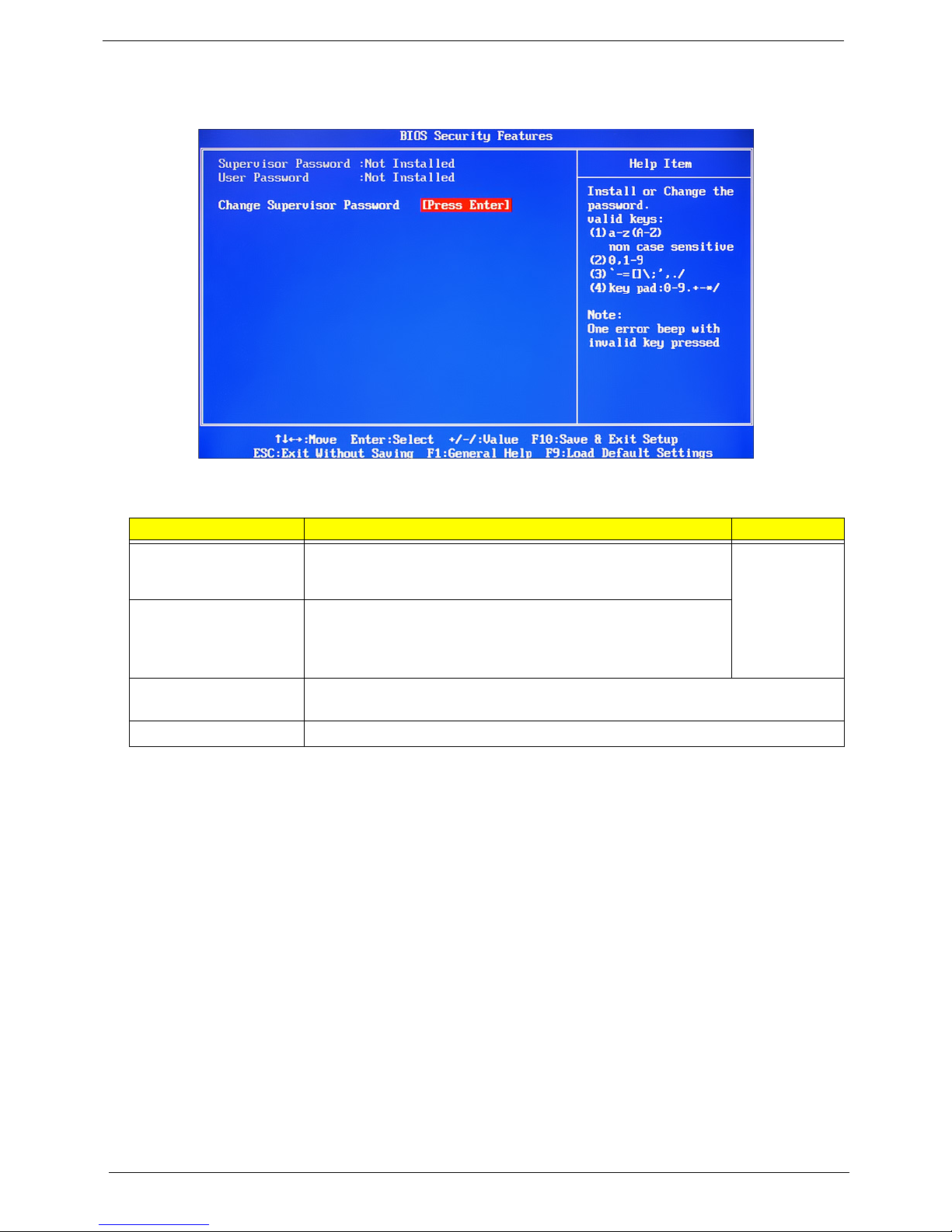
BIOS Security Features
Field Description Value
Supervisor Password Displays the supervisor password status. When set to Installed,
this password will allow the user to access and change all settings
in the Setup Utility.
User Password Displays the user password status. Only the following menus will
be accessible when this password is set as Installed:
• System Time and System Date
• Exit Without Saving
Change Supervisor
Password
Change User Password
Press Enter to change the supervisor password.
Press Enter to change the user password.
Installed
Not Installed
Setting a supervisor password
Note the following before you define a system password:
• The maximum length of password contains 8 alphanumeric characters—A - Z, 0 - 9, and ‘;’
(for French keyboard).
• System passwords are case-insensitive.
• When you are prompted to enter a password, you have three tries before the system halts. Do not forget
your password. If you forget your password, you may have to return your computer to your dealer to reset
it.
18 EL1358 Service Guide

To set a system password:
1. Select Change Supervisor Password or Change User Password, then press Enter.
The password box appears.
2. Type a password then press Enter.
IMPORTANT Be very careful when typing your password because the characters do not appear on the
screen. Only shaded blocks representing each typed character are visible.
3. Retype the password to verify the first entry, then press Enter.
You will be prompted to save the new password.
4. Press Enter.
5. Press F10 to save the password and close the Setup Utility.
To change a system password:
1. Select Change Supervisor Password or Change User Password, then press Enter.
The password box appears.
2. Type the original password, then press Enter.
3. Type a new password, then press Enter.
4. Retype the new password to verify the first entry, then press Enter.
You will be prompted to save the new password.
5. Press Enter.
6. Press F10 to save the password and close the Setup Utility.
To remove a system password:
1. Select Change Supervisor Password or Change User Password, then press Enter.
The password box appears.
2. Type the original password, then press Enter.
3. Press Enter twice without entering anything in the new and confirm password fields.
You will be prompted to confirm the password removal.
4. Press Enter.
5. Press F10 to save the changes you made and close the Setup Utility.
EL1358 Service Guide 19
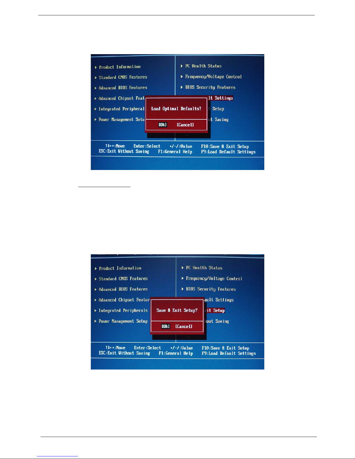
Load Default Settings
Execute this menu to load the factory-default settings for all Setup parameters. Keyboard shortcut: F9
Perform the steps below to load the system default settings:
1. Select Load Default Settings, then press Enter.
You will be prompted to load the system defaults.
2. Select OK, then press Enter.
3. Press F10 to save the changes you made and close the Setup Utility.
Save & Exit Setup
Execute this menu to save the changes made and closes the Setup Utility. Keyboard shortcut: F10
20 EL1358 Service Guide
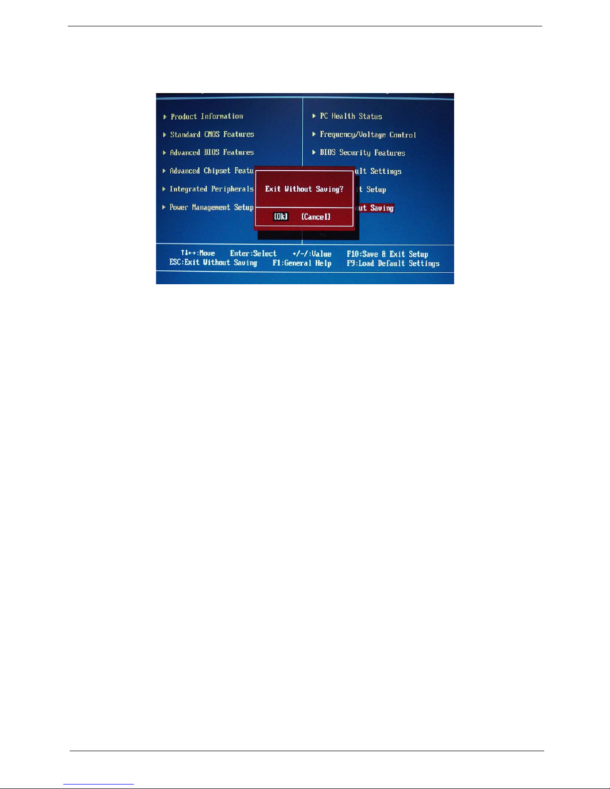
Exit Without Saving
The Exit Without Saving menu allows you to discard changes made and close the Setup Utility.
EL1358 Service Guide 21

22 EL1358 Service Guide
 Loading...