

Page 1

SoM-210ES
SoM 200-pin Carrier Board
User Manual
REV. 0.1
Copyright 2010,
EMAC, Inc.
Page 2

Table of Contents
Disclaimer.................................................................................................................................................. 1
1 SOM-210 Product Summary.............................................................................................................2
1.1 Features........................................................................................................................................................................2
1.2 Standard PPC Specifications........................................................................................................................................3
2 SOM-210 Product Details.................................................................................................................. 4
2.1 Jumper Configuration & Connector Descriptions........................................................................................................4
2.2 Power Connectors........................................................................................................................................................5
2.3 Ethernet........................................................................................................................................................................5
2.4 Serial Ports...................................................................................................................................................................5
2.5 USB Host Ports............................................................................................................................................................7
2.6 Audio Port (option on Rev1 and greater boards) .........................................................................................................7
2.7 LCD Brightness Control..............................................................................................................................................7
2.8 SD/MMC Card Socket.................................................................................................................................................7
2.9 Keyboard/Mouse..........................................................................................................................................................7
2.10 Analog Inputs...............................................................................................................................................................7
2.11 I/O Expansion..............................................................................................................................................................7
2.12 Real-Time Clock..........................................................................................................................................................8
2.13 Reset ............................................................................................................................................................................8
3 Software............................................................................................................................................... 9
3.1 Introduction..................................................................................................................................................................9
4 Appendix A: Connector Pinouts...................................................................................................... 10
4.1 Ethernet 10/100 Base-T connector (JK1) ...................................................................................................................10
4.2 USB Host connector Port A & B (JK3 and JK2).......................................................................................................10
4.2.1 PortA..................................................................................................................................................................10
4.2.2 PortB..................................................................................................................................................................10
4.3 Power Jack (JK4).......................................................................................................................................................10
4.4 Power Connector (HDR1)..........................................................................................................................................10
4.5 Micro SD Socket (SOK2)..........................................................................................................................................10
4.6 LCD/Touch/Backlight (SOK3)..................................................................................................................................11
4.7 COMA RS-232 Serial Port (HDR5) .........................................................................................................................12
4.8 COMB RS-232 Serial Port (HDR4)..........................................................................................................................12
4.9 COMC RS-232/422/485 Serial Port (HDR3) ...........................................................................................................12
4.10 JTAG Connector (HDR6)..........................................................................................................................................12
4.11 Misc. I/O (HDR2)......................................................................................................................................................13
5 Appendix B: Jumper Settings .......................................................................................................... 14
6 Appendix C: Mechanical drawing with dimensions....................................................................... 15
Page 3

Disclaimer
EMAC Inc. does not assume any liability arising out of the application or use of any of its products or designs.
Products designed or distributed by EMAC Inc. are not intended for, or authorized to be used in, applications such
as life support systems or for any other use in which the failure of the product could potentially result in personal
injury, death or property damage.
If EMAC Inc. products are used in any of the aforementioned unintended or unauthorized applications, Purcha ser
shall indemnify and hold EMAC Inc. and its employees and officers harmless against all claims, costs, damages,
expenses, and attorney fees that may directly or indirectly arise out of any claim of personal injury, death or
property damage associated with such unintended or unauthorized use, even if it is alleged that EMAC Inc. was
negligent in the design or manufacture of the product.
EMAC Inc. reserves the right to make changes to any products with the intent to improve overall quality, without
further notification.
ENG-00161-01P-SoM-210ES_User_Manual.doc -1- Rev 0.1 © 2010 EMAC, Inc.
Page 4

1 SOM-210 Product Summary
Features
200 Pin SODIMM SoM Connector
10/10 0BaseT Ethernet
3 Serial ports with handshake
2 USB 2.0 (Full Speed) Host ports
Battery for Real Time Clock
MicroSD Flash Card Interface
1 Audio Beeper
General purpose I/O connector to give access to SoM peripherals such as SPI, I2S, Timer/Counters and
Pulse Width Modulation (PWM) ports
WQVGA LCD (480 x 272) Resolution with LED Backlight
Touchscreen Interface and Software Controlled Backlight On/Off & Brightness
JTAG connector for debug
FREE Eclipse IDE with GCC & GDB development tools
Linux BSP and SDK available
WinCE 6.0 BSP and SDK available
ENG-00161-01P-SoM-210ES_User_Manual.doc -2- Rev 0.1 © 2010 EMAC, Inc.
Page 5

1.1 Specifications
LCD
• Display Type: 4.3" TFT Color LCD
• Resolution: 400 x 272 WQVGA @ 256K Colors
• Dot pitch: 0.198mm x 0.198mm
• Luminance: 330 (cd/m²)
• Viewing Angle: 55°
• Brightness: Software controlled
• Backlight: White LED (10 LEDS)
Touchscreen
• Type: 4 Wire Analog Resistive
• Resolution: Continuous
• Light Transparency: 80%
• Controller: Built-In
• Driver: WinCE, Linux
• Durability: Over one million touches
Ethernet interface
• Ethernet Type: 10/100 Base-T Ethernet
• Ethernet Interface: On-Board RJ-45 connector
Solid-state Flash Disk
• Removable: 8+ GB of SD, MMC, or SDHC Flash Disk
Mechanical and Environmental
• Dimensions: 4.8 " L x 3.0" W x 1.2" H
• Weight: 5.7 oz.
• Power Supply Voltage: +5V DC.
• Power Consumption: typical <~1.0A. @ 5V DC.
• Operating Temperature: 0 ~ 60° C (32 ~ 140° F)
Standard Parts Inventory
• SOM-210 Assembly with 4.3” Touchscreen
• Molded plastic LCD mounting bracket and standoffs
• Three Serial Port cables
• CDROM with manuals, schematics, and drivers
ENG-00161-01P-SoM-210ES_User_Manual.doc -3- Rev 0.1 © 2010 EMAC, Inc.
Page 6
2 SOM-210 Product Details
2.1 Jumper Configuration & Connector Descriptions
The SOM-210 comes factory configured. In the event that jumpers need to be verified or modified this section
provides the information required, including instructions on setting jumpers and connecting peripherals, switches
and indicators. Be sure to read all the safety precautions before you begin any configuration procedure. See
Appendix A for connector pinouts and Appendix B for Jumper Settings.
Table 1: Jumpers
Label Function Default
JB1 Boot Source Selection Position A
JB2 Boot Source Selection Position A
Table 2: Connectors
Label Function
JK1 Ethernet
JK2 USB B
JK3 USB A
JK4 5v power barrel jack
HDR1 Power
HDR2 I/O Interface
HDR3 COM C COM 3 Serial Port
HDR4 COM B COM 2 Serial Port
HDR5 COM A COM 1 Serial Port
HDR6 BDM JTAG
SOK1 200 pin SOM Socket
SOK2 MicroSD Card Socket
SOK3 LCD &Touch Interface Cable Socket
ENG-00161-01P-SoM-210ES_User_Manual.doc -4- Rev 0.1 © 2010 EMAC, Inc.
Page 7

2.2 Power Connectors
The SOM-210 provides two power connectors. HDR4 is a standard PC Floppy disk power connector, four-pin
type connector that mates with standard Floppy disk drive power connector. Using this power input provides for a
more rugged/industrial locking connection. JK4 is a standard 5.5mm barrel jack with an inner diameter of 2.1mm
with a center V+ connection. This jack allows for easy connection to a wall mount power supply (EMAC part
number PER-PWR-00032). The SOM-210’s power input uses a switching regulator and allows a voltage input of
+5V DC.
The pinout for the J1 power connector is as follows:
Pin Signal
1 +5V DC
2 Chassis GND
3 Chassis GND
4 +12V DC (unused)
2.3 Ethernet
The SOM-210 provides 10/100 Base-T full duplex Ethernet and uses a standard RJ-45 connector. It can be
connected straight to a hub, or another computer via a crossover Ethernet cable. The Ethernet MAC & PHY are
integrated into the SoM processor module. Activity and Link LEDs are integrated into the RJ45 connector.
2.4 Serial Ports
The SOM-210 is equipped with three serial ports, all of which terminate to 10pin header connectors (see table 2,
3, & 4 below). Three 10-pin header to male DB9 connector cables are provided, giving easy access to these
ports. Baud Rate, stop bits, etc. are all programmable for each port via software.
COM A is an RS232 compatible port with a full complement of handshaking lines allowing it to communicate with
modems and other devices requiring hardware flow control.
COM B is an RS232 port. This port offers the RTS and CTS handshake lines.
COM C can be configured to RS232, RS422, and RS485 via 4 software controlled port pins (see table 1 below).
To select RS232 set SoM pin 113 & 120 Low and pin 118 & 119 High (this is the default). For RS422 set SoM pin
113 & 120 High and pin 118 & 119 Low. To select RS485, selectively set SoM pin 113 & 119 as required while
keeping pin 118 Low.
When using COM C in the RS422/485 mode, a terminating resistor (~120 Ohm) is recommended on the two far
ends of the network.
Table 1
SODIMM Pin# SoM Pin Name
113 COMD_RTS RS422/485 Tx Enable
118 GPIO4 ~RS232 Shutdown
119 GPIO5 ~RS422/485 Rx Enable
120 GPIO6 ~RS232 Enable
Function
ENG-00161-01P-SoM-210ES_User_Manual.doc -5- Rev 0.1 © 2010 EMAC, Inc.
Page 8

Table 2 (COM A Pinout)
#
1 DCD DCD
2 DSR RxD
3 RxD TxD
4 RTS DTR
5 TxD GND
6 CTS DSR
7 DTR RTS
8 RI CTS
9 GND RI
10 NC -
Table 3 (COM B Pinout)
#
1 NC NC
2 NC RxD
3 RxD TxD
4 RTS NC
5 TxD GND
6 CTS NC
7 NC RTS
8 NC CTS
9 GND NC
10 NC -
Pin Description for 10Pin Header
Pin Description for 10Pin Header
Pin Description for DB9
Connector
Pin Description for DB9
Connector
Table 4 (COM C Pinout)
#
1 422/485 TX- 422/485 TX-
2 NC 232 RX, 422/485 TX+
3 232 RX, 422/485 TX+ 232 TX, 422/485 RX+
4 RTS 422/485 RX-
5 232 TX, 422/485 RX+ GND
6 CTS NC
7 422/485 RX- RTS
8 NC CTS
9 GND NC
10 NC -
Pin Description for 10-Pin
Header
Pin Description for DB9
Connector
ENG-00161-01P-SoM-210ES_User_Manual.doc -6- Rev 0.1 © 2010 EMAC, Inc.
Page 9

2.5 USB Host Ports
The SOM-210 provides two, USB 2.0 full speed host ports. USB PortA and PortB can be accessed from the onboard USB connectors JK3 and JK2.
All of the USB ports are equipped with 500mA re-settable Polyfuses. If a USB Device tries to draw more than
500mA from the port, the fuse will open until the device is unplugged or its current requirement is reduced. There
is no software provision for shutting down power to the Ports or detecting when a port is drawing too much
current.
Note: When sizing a power supply, make sure to allow for USB Device consumption. A device can potentially
draw 500mA, therefore these devices could use a total of up to 1 amp of power.
2.6 Audio Port (option on Rev1 and greater boards)
The SOM-210 provides Audio Line Out and Line In capability through a 10-pin 2mm header. A special cable
converts the signals present on the header to two miniature audio jacks. The processor interfaces to the Audio
CODEC through its I
The CODEC is the Cirrus CS4271, which is a high performance 24-bit Stereo CODEC offering superior sound
quality.
Both the input and output are line level. You will probably not be able to drive an unamplified speaker although
standard headphones will work. Likewise, an un-amplified microphone probably will not work as an input although
the line out of a CD player will work.
2
S interface. Command control of the CODEC is done using the processor’s SPI interface.
2.7 LCD Brightness Control
The SOM-210 offers LCD brightness control that can change the brightness of the LCD via software. The LCD
utilizes LED backlighting. The board provides the backlight with approximately 33 volts at about 20mA. The
processor provides a PWM that is used to drive the LCD backlight. Changing the duty-cycle of the PWM directly
affects the brightness of the LCD. In addition, the backlight can be turned off by reducing the PWM rate to 0. This
allows screensaver software to automatically turn off the backlight when the unit is not being used and to
automatically turn it back on when the touchscreen is touched.
2.8 MicroSD Card Socket
The SOM-210 provides a high capacity MicroSD socket. This socket is hot-swappable and can accept a wide
variety of Flash Cards. A green activity light (LED LD2) is located towards the left side of the socket. When the
processor is accessing the Flash card this LED will be lit and the card should not be removed at this time. A card
that is written to by the SOM-210 can be read by another computer using an MicroSD card reader. The MicroSD
interface is compatible with Standard and High Capacity MicroSD cards.
2.9 Keyboard/Mouse
The SOM-210 does not provide a PS/2 type keyboard/mouse interface. However, a USB keyboard and mouse
can be used if required.
2.10 Analog Inputs
The analog inputs are available on HDR2 (see table 5 below) and are labeled as analog_04, analog_05,
analog_06 and analog_07. These may or may not be supported by the SoM plugged into this carrier.
2.11 I/O Expansion
The Processor used by the SOM-210 provides a number of unused I/O lines. The SOM-210 provides access to
these lines on connector HDR2. This 30-pin dual row header contains GPIO lines, SPI bus, I
interrupts and power pins. Signal names listed in the table below are the SoM names as defined in the SoM 200
pin specification.
2
C bus, A/D lineS,
ENG-00161-01P-SoM-210ES_User_Manual.doc -7- Rev 0.1 © 2010 EMAC, Inc.
Page 10

Pin
1 GND 2 3.3V
3 CANRX 4 CANTX
5 I2DAT 6 I2CLK
7 RESET_OUT 8 SPI_MI
9 SPI_CK 10 SPI_MO
11 SPI_CS1 12 SPI_CS0
13 SPI_CS3/FRM 14 SPI_CS2
15 AUD_DOUT 16 AUD_MCLK
17 ANALG_05 18 AUD_SCLK
19 ANALG_07 20 AUD_DIN
21 ANALG_04 22 AUD_LRCLK
23 GPIO12 24 GPIO11
25 ANALG_06 26 GPIO13
27 GPIO15 28 IRQA
29 3.3V 30 GND
Signal Pin Signal
2.12 Real-Time Clock
The SOM-210 is equipped with an external battery for backing up the module’s Real-Time Clock (RTC). Drivers to
access the RTC are included in the operating systems.
2.13 Reset
The SOM-210 provides a Reset Button (PB1). Pressing this button will cause the system to reset.
ENG-00161-01P-SoM-210ES_User_Manual.doc -8- Rev 0.1 © 2010 EMAC, Inc.
Page 11

3 Software
3.1 Introduction
Whatever module is used in the SOM-210 can be programmed in a variety of languages and utilize a variety of
Operating Systems. There are a number of Free compilers, interpreters, and assemblers available allowing the
processor module to be programmed in C, BASIC or Assembly languages. EMAC has Board Support Packages
available for Linux and Windows CE. For more information on these particular Operating Systems, contact EMAC,
Inc.
For more information on Software, see the module’s User’s Manual.
Note: All of the links in this document are subject to change. Please contact EMAC for updated link locations if
necessary.
ENG-00161-01P-SoM-210ES_User_Manual.doc -9- Rev 0.1 © 2010 EMAC, Inc.
Page 12

4 Appendix A: Connector Pinouts
4.1 Ethernet 10/100 Base-T connector (JK1)
Pin Signal
1 XMT+
2 XMT3 RCV+
4 N/C
5 N/C
6 RCV7 N/C
8 N/C
4.2 USB Host connector Port A & B (JK3 and JK2)
4.2.1 PortA
Pin Signal
1 USB_PWR (5V DC)
2 USB_Data-
3 USB_Data+
4 GND
4.2.2 PortB
Pin Signal
1 USB_PWR (5V DC)
2 USB_Data-
3 USB_Data+
4 GND
4.3 Power Jack (JK4)
Pin Signal
Center 5V DC
Barrel GND
4.4 Power Connector (HDR1)
Pin Signal
1 5V DC
2 GND
3 GND
4 +Vin
4.5 MicroSD Socket (SOK2)
Pin Signal
1 DAT2
2 CD/DAT3
3 CMD
4 VCC (3.3V)
5 SCLK
6 GND
7 DAT0
8 DAT1
9 SD Card Detect
10 GND
ENG-00161-01P-SoM-210ES_User_Manual.doc -10- Rev 0.1 © 2010 EMAC, Inc.
Page 13

4.6 LCD/Touch/Backlight (SOK3)
Pin Signal
1 NC
2 NC
3 Backlight LED+
4 Backlight LED-
5 GND
6 Touch X1
7 Touch Y1
8 Touch X2
9 Touch Y2
10 GND
11 VDDSEL 3.3V/~2.5V
12 DATA ENABLE
13 VSYNC
14 HSYNC
15 Display ON/~OFF
16 Data CLK
17 GND
18 B7
19 B6
20 B5
21 B4
22 B3
23 B2
24 B1
25 B0
26 G7
27 G6
28 G5
29 G4
30 G3
31 G2
32 G1
33 G0
34 R7
35 R6
36 R5
37 R4
38 R3
39 R2
40 R1
41 R0
42 VDD
43 VDD
44 GND
45 GND
ENG-00161-01P-SoM-210ES_User_Manual.doc -11- Rev 0.1 © 2010 EMAC, Inc.
Page 14

4.7 COMA RS-232 Serial Port (HDR5)
Pin HD3 Signal DB9 Signal
1 DCD DCD
2 DSR RxD
3 RxD TxD
4 RTS DTR
5 TxD GND
6 CTS DSR
7 DTR RTS
8 RI CTS
9 GND RI
10 NC -
4.8 COMB RS-232 Serial Port (HDR4)
Pin HD3 Signal DB9 Signal
1 NC NC
2 NC RxD
3 RxD TxD
4 RTS NC
5 TxD GND
6 CTS NC
7 NC RTS
8 NC CTS
9 GND NC
10 NC --
4.9 COMC RS-232/422/485 Serial Port (HDR3)
Pin HD3 Signal DB9 Signal
1 422/485 TX- 422/485 TX-
2 NC 232 RX, 422/485 TX+
3 232 RX, 422/485 TX+ 232 TX, 422/485 RX+
4 RTS 422/485 RX-
5 232 TX, 422/485 RX+ GND
6 CTS NC
7 422/485 RX- RTS
8 NC CTS
9 GND NC
10 NC -
4.10 JTAG Connector (HDR6)
Pin Signal Pin Signal
1 VCC (3V) 2 GND
3 TRST 4 GND
5 TDI 6 NC
7 TMS 8 NC
9 TCK 10 NC
11 TDO 12 NC
13 NC 14 NC
ENG-00161-01P-SoM-210ES_User_Manual.doc -12- Rev 0.1 © 2010 EMAC, Inc.
Page 15

4.11 Misc. I/O (HDR2)
Pin Signal Pin Signal
1 GND 2 3.3V
3 CANRX 4 CANTX
5 I2DAT 6 I2CLK
7 RESET_OUT 8 SPI_MI
9 SPI_CK 10 SPI_MO
11 SPI_CS1 12 SPI_CS0
13 SPI_CS3/FRM 14 SPI_CS2
15 AUD_DOUT 16 AUD_MCLK
17 ANALG_05 18 AUD_SCLK
19 ANALG_07 20 AUD_DIN
21 ANALG_04 22 AUD_LRCLK
23 GPIO12 24 GPIO11
25 ANALG_06 26 GPIO13
27 GPIO15 28 IRQA
29 3.3V 30 GND
ENG-00161-01P-SoM-210ES_User_Manual.doc -13- Rev 0.1 © 2010 EMAC, Inc.
Page 16

5 Appendix B: Jumper Settings
JB1 Boot Source Selection
Jumper Position Setting
Pins 1 & 2 A Serial Boot Loader Download
Pins 2 & 3* B Normal Boot from NOR Flash
* Default setting
JB2 Boot Option Selection
Jumper Position Setting
Pins 1 & 2 A Not Used
Pins 2 & 3* B Not Used
* Default Setting
ENG-00161-01P-SoM-210ES_User_Manual.doc -14- Rev 0.1 © 2010 EMAC, Inc.
Page 17
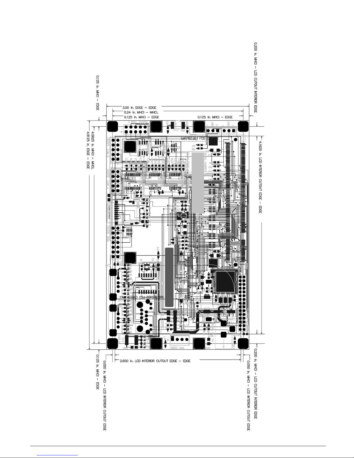
6 Appendix C: Mechanical drawing with dimensions
ENG-00161-01P-SoM-210ES_User_Manual.doc -15- Rev 0.1 © 2010 EMAC, Inc.
 Loading...