

Page 1

2390 EMAC Way, Carbondale, Illinois 62902
Phone: (618) 529-4525 Fax: (618) 457-0110
http://www.emacinc.com
SoM-112ES
User Manual
July 2018
Revision 1.00
Copyright © 2018
EMAC, Inc.
Page 2

SoM-112ES User Manual
Table of Contents
1 Introduction ........................................................................................................................................................... - 4 -
1.1 .... Features ............................................................................................................................................................................. - 4 -
2 Hardware ................................................................................................................................................................ - 5 -
2.1 .... Specifications .................................................................................................................................................................. - 5 -
2.2 .... Jumper Configuration & Connector Descriptions ............................................................................................. - 6 -
2.3 .... Power Connectors ......................................................................................................................................................... - 7 -
2.4 .... Ethernet ............................................................................................................................................................................. - 7 -
2.5 .... Serial Ports ....................................................................................................................................................................... - 7 -
2.6 .... USB ...................................................................................................................................................................................... - 9 -
2.7 .... CAN Port ............................................................................................................................................................................ - 9 -
2.8 .... MicroSD Card Socket .................................................................................................................................................... - 9 -
2.9 .... Audio ................................................................................................................................................................................. - 10 -
2.10 .. Wi-Fi [Optional] ............................................................................................................................................................ - 10 -
2.11 .. I/O Expansion ................................................................................................................................................................ - 10 -
2.12 .. Mikrobus Expansion ................................................................................................................................................... - 11 -
2.13 .. I2C ...................................................................................................................................................................................... - 11 -
2.14 .. SPI ...................................................................................................................................................................................... - 11 -
2.15 .. Status LEDs and Reset ............................................................................................................................................... - 11 -
2.16 .. Real-Time Clock ............................................................................................................................................................ - 12 -
3 Software ................................................................................................................................................................ - 12 -
3.1 .... Das U-Boot ..................................................................................................................................................................... - 12 -
3.2 .... Embedded Linux ........................................................................................................................................................... - 12 -
3.2.1 Linux with Xenomai Real Time Extensions .................................................................................................................. - 13 -
3.2.2 Linux Packages ...................................................................................................................................................................... - 13 -
3.2.3 Linux Patches ......................................................................................................................................................................... - 13 -
3.3 .... Qt Creator ....................................................................................................................................................................... - 13 -
3.4 .... ARM EABI Cross Compiler ........................................................................................................................................ - 13 -
4 Appendix A: Connector Pinouts .................................................................................................................... - 14 -
4.1 .... 4-Pin Molex Male Floppy Power Connector (CN1) ..................................................................................... - 14 -
4.2 .... 3-Pin Polarized Locking CAN Connector (CN2) ........................................................................................... - 14 -
4.3 .... Utility GPIO Header (HDR1) .................................................................................................................................. - 14 -
Revision 1.00 © 2018 - 1 -
Page 3

SoM-112ES User Manual
4.4 .... RS-232 Serial Port COM A Header (HDR2)..................................................................................................... - 15 -
4.5 .... RS-232/422/485 Serial Port COM B Header (HDR3) ................................................................................ - 15 -
4.6 .... Audio Input Jack (JK1) ............................................................................................................................................. - 15 -
4.7 .... Audio Output Jack (JK2) .......................................................................................................................................... - 15 -
4.8 .... Serial Port COM C (JK3) ........................................................................................................................................... - 16 -
4.9 .... Micro USB B 2.0 Console Interface Connector (JK4) .................................................................................. - 16 -
4.10 .. USB Host Port B (JK5) .............................................................................................................................................. - 16 -
4.11 .. USB Host Port A1 & A2 (JK6) ................................................................................................................................ - 17 -
4.12 .. USB Device Port C (JK7) .......................................................................................................................................... - 17 -
4.13 .. Single Port Ethernet Connector (JK8)............................................................................................................... - 17 -
4.14 .. Vin Power Barrel Jack (JK10) ............................................................................................................................... - 18 -
4.15 .. MikroBUS Socket (SOK2) ........................................................................................................................................ - 18 -
4.16 .. Micro SD Card Socket (SOK3) ............................................................................................................................... - 18 -
5 Appendix B: Jumper Settings ................................................................................................................... - 19 -
5.1 .... JB1 (Boot0 Source Selection) ................................................................................................................................ - 19 -
5.2 .... JB2 (Boot1 Source Selection) ................................................................................................................................ - 19 -
5.3 .... JB3 (Flash Write Protect) ....................................................................................................................................... - 19 -
5.4 .... JB4 (Standby Battery) .............................................................................................................................................. - 19 -
5.5 .... JB5 (External SPI Interface Voltage) ................................................................................................................ - 19 -
5.6 .... JB6 (External I2C Interface Voltage) ................................................................................................................ - 19 -
5.7 .... JB7 (Serial Port RS-232 or RS-422/485) ......................................................................................................... - 20 -
5.8 .... JB8 (Serial Port RS-422 or RS-485) ................................................................................................................... - 20 -
5.9 .... JB9 (USB Device Port C Enable) ........................................................................................................................... - 20 -
6 Appendix C: Dimensional Drawing ...................................................................................................... - 21 -
Revision 1.00 © 2018 - 2 -
Page 4

SoM-112ES User Manual
Disclaimer
EMAC Inc. does not assume any liability arising out of the application or use of any of its
products or designs. Products designed or distributed by EMAC Inc. are not intended for, or
authorized to be used in, applications such as life support systems or for any other use in which
the failure of the product could potentially result in personal injury, death or property damage.
If EMAC Inc. products are used in any of the aforementioned unintended or unauthorized
applications, Purchaser shall indemnify and hold EMAC Inc. and its employees and officers
harmless against all claims, costs, damages, expenses, and attorney fees that may directly or
indirectly arise out of any claim of personal injury, death or property damage associated with
such unintended or unauthorized use, even if it is alleged that EMAC Inc. was negligent in the
design or manufacture of the product.
EMAC Inc. reserves the right to make changes to any products with the intent to improve
overall quality, without further notification.
Revision 1.00 © 2018 - 3 -
Page 5

SoM-112ES User Manual
1 Introduction
This document provides information regarding EMAC’s SoM-112ES System-on-Module Carrier Board.
The SoM-112ES is a compact, low-power SoM Carrier/Socket board with WiFi and Bluetooth
connectivity onboard, and MikroBus expansion. This versatile SoM Carrier/Socket board is ideal for
evaluation and early development work. This Carrier is designed to work with all EMAC 144-pin
SODIMM type SoMs. Note: The SoM-112ES is specifically designed for SoMs with APM sleep capability
and utilizes GPIO controllable IO to further reduce sleep current draws.
The SoM-112ES provides access to many of the SoM's I/O through on-board connectors as well as a
number of additional I/O expansion blocks such as Wireless Networking, 10/100 BaseT Ethernet,
MikroBUS modules, and HCSD/MMC flash disk.
When paired with the SOM-IMX6U, the SOM-112ES makes a relatively Low Power IoT connectivity
solution, using a MikroBUS ZigBee Wireless module, the SOM-112ES can collect and route IoT sensors to
the Cloud.
1.1 Features
114 Pin SODIMM SoM Connector
2x serial RS232 ports, 1x USB to Serial Console, & 1x RS232/422/485 Port
3x USB Host ports & 1x USB Device Port
1x 10/100 BaseT Ethernet with onboard Magnetics and RJ45
Wifi/BT & CAN 2.0B Port
General SOM I/O: GPIOs, SPI, A/D, D/A, PWM, I²C, I²S
MikroBus Expansion
Barrel power jack
Standard Molex male floppy power connector for alternate power input
DB9 male for COM C
3x 10 pin header for serial ports
1x micro USB connector for serial console
1x dual USB Type A connector
1x single USB Type A connector
1x mini USB Device Type B connector
1x RJ45 Ethernet connector
1x Micro SD Card Socket
1x 3-pin polarized locking connector for CAN
1x dual row 50-pin .1” GPIO/Misc. Header connector
1x I²S audio with Line in & out jacks
Reset Button
Revision 1.00 © 2018 - 4 -
Page 6

SoM-112ES User Manual
2 Hardware
2.1 Specifications
Flash Disk: Micro SD Card Socket
System Reset: External Reset Button
RTC: Real-Time Clock with battery-backed provision
Multi I/O: (any mix of)
o Up to 8x General Purpose Digital Inputs
o Up to 8x General Purpose Digital Outputs
o Up to 8x 12-bit Digital-to-Analog Converter (DAC)
o Up to 8-channel, 12-bit Analog-to-Digital Converter (ADC)
Power: Barrel Jack or Standard 4-Pin Molex Male Connectors with 3.3 linear regulator
Serial Interfaces:
UARTS: 4x Serial Ports (2xRS232, 1xRS232/422/485, 1x USB Device to Serial Console)
Audio: 1x I²S audio with Line in & out jacks
USB: 3x USB Host ports & 1x USB Device Port
Ethernet Interface:
Type: 10/100 BaseT Ethernet with onboard Magnetics and RJ45
Interface: On-Board RJ-45 Connector
Bus Interface:
SoM Bus: 144-Pin SODIMM SOM Module
Bus Expansion.: MikroBUS Expansion Socket (MikroBUS module Optional)
Mechanical and Environmental
Dimensions: 3" W × 4 .75" L × 0.75" H (76mm × 120mm × 19mm)
Power Supply Voltage: +5 V power input
o Power Requirements (typical): 5 Volts @ ~500mA (2.5 watts)
Operating Temperature: 0 to 70° C (32 ~158° F) [-40 to +85° C optional]
Operating Humidity: 0% ~ 90% relative humidity, non-condensing
Revision 1.00 © 2018 - 5 -
Page 7
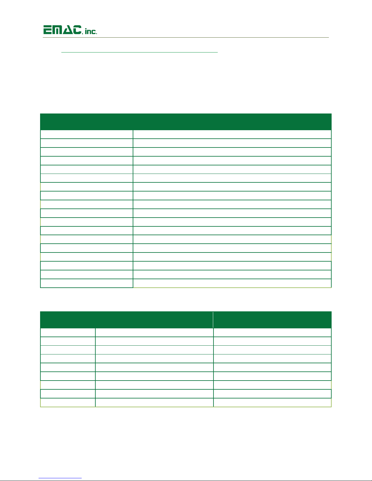
SoM-112ES User Manual
Label
Function
CN1
4-Pin Molex Male Floppy Power Connector
CN2
3-Pin Polarized Locking CAN Connector
HDR1
Utility GPIO Header
HDR2
RS-232 Serial Port COM A Header
HDR3
RS-232/422/485 Serial Port COM B Header
JK1
Audio Input Jack
JK2
Audio Output Jack
JK3
Serial Port COM E
JK4
Micro USB 2.0 Console Interface Connector
JK5
USB Host Port B
JK6
USB Host Port A1 & A2
JK7
USB Device Port C
JK8
Single Port Ethernet Connector
JK9
WiFi Antenna Connector
JK10
Vin Power Barrel Jack
SOK1
144 Pin SoM Socket
SOK2
MikroBUS Socket
SOK3
Micro SD Card Socket
Label
Function
Default
JB1
Boot0 Source Selection
Position A
JB2
Boot1 Source Selection
Position A
JB3
Flash Write Protect
Position A
JB4
Standby Battery
ON
JB5
External SPI Interface Voltage
3.3V
JB6
External I2C Interface Voltage
3.3V
JB7
Serial Port RS-232 or RS-422/485
232
JB8
Serial Port RS-422 or RS-485
422
JB9
USB Device Port C Enable
Position B
2.2 Jumper Configuration & Connector Descriptions
The SoM-112ES is factory configured. In the event that jumpers need to be verified or modified this
section provides the information required, including instructions on setting jumpers and connecting
peripherals, switches and indicators. Be sure to read all the safety precautions before you begin any
configuration procedure. See Appendix A for connector pinouts and Appendix B for Jumper Settings.
Table 1: Connectors
Table 2: Jumpers
Revision 1.00 © 2018 - 6 -
Page 8
SoM-112ES User Manual
Pin
Signal
Pin 1
5V
Pin 2
GND
Pin 3
GND
Pin 4
12V
Pin
RS-232 10-Pin Header: Description
1
NC 2 NC
3
COMA_RX232
4
NC
5
COMA_TX232
6
NC 7 NC 8 NC
9
GND
10
NC
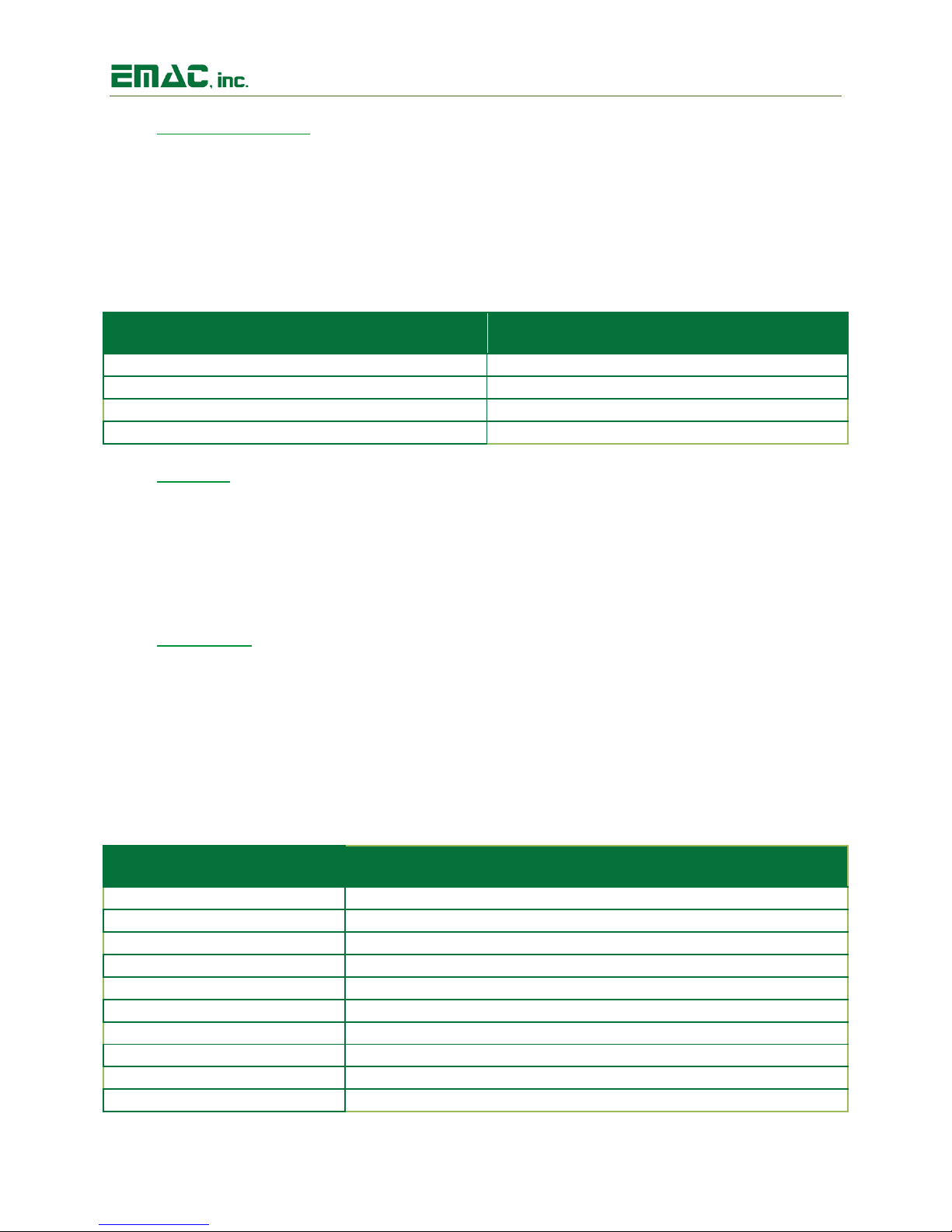
2.3 Power Connectors
The SoM-112ES provides two power connectors. JK10 is a standard 5.5mm barrel jack with an inner
diameter of 2.1mm with a center V+ connection and has an operating temperature of -25 ~ 85°C. This
jack allows for an easy connection to a wall mount power supply (EMAC part number PER-PWR-00032).
An alternative power connector is located at CN1 and is an On-Shore Technology locking power
connector (part# 254B5V1040). This power input provides a more rugged/industrial locking connection
with an operating temperature of -25 ~ 85°C.
Table 3: Pin-out for Power Connector (CN1)
2.4 Ethernet
The SoM-112ES provides one 10/100 Base-T full duplex Ethernet and uses a standard single port RJ-45
LAN jack (JK8) with integrated magnetics. It can be connected straight to a hub, or another computer
via Ethernet crossover cable. The Ethernet crossover cable can be replaced with a patch cable if the SoM
processor module supports the Auto MDI-X capability. The Ethernet MAC & PHY are integrated into the
SoM processor module. Activity and Link LEDs are integrated into the RJ45 connector.
2.5 Serial Ports
The SoM-112ES is equipped with four serial ports, two that terminate to 10-pin header connectors
(COM A & B), one of which terminates to a male DB9 connector (COM C), and one USB to Serial console
port that terminates to a micro USB 2.0 B connector (COM E). COM D is dedicated to the Bluetooth
Radio. Baud Rates, stop bits, etc. are all programmable for each port via software.
Serial Port COM A is a RS232 port. This port offers RXD/TXD without handshaking lines
terminating to a 10-pin header.
Table 4: Serial Port COM A (HDR2)
Revision 1.00 © 2018 - 7 -
Page 9
SoM-112ES User Manual
Pin
RS-232 10-Pin Header: Description
RS-422/485 10-Pin Header: Description
1
NC
COMB_422/485_TX-
2
NC
NC
3
COMB_232RX
COMB_422/485_TX+
4
COMB_232_RTS
NC
5
COMB_232TX
COMB_422/485_RX+
6
COMB_232_CTS
NC 7 NC
COMB_422/485_RX-
8
NC
NC
9
GND
GND
10
NC
NC
Pin
DB9 Connector: Description
1
COMC_232_DCD
2
COMC_232_RXD
3
COMC_232_TXD
4
COMC_232_DTR
5
COMC_232_GND
6
COMC_232_DSR
7
COMC_232_RTS
8
COMC_232_CTS
9
COMC_232_RI
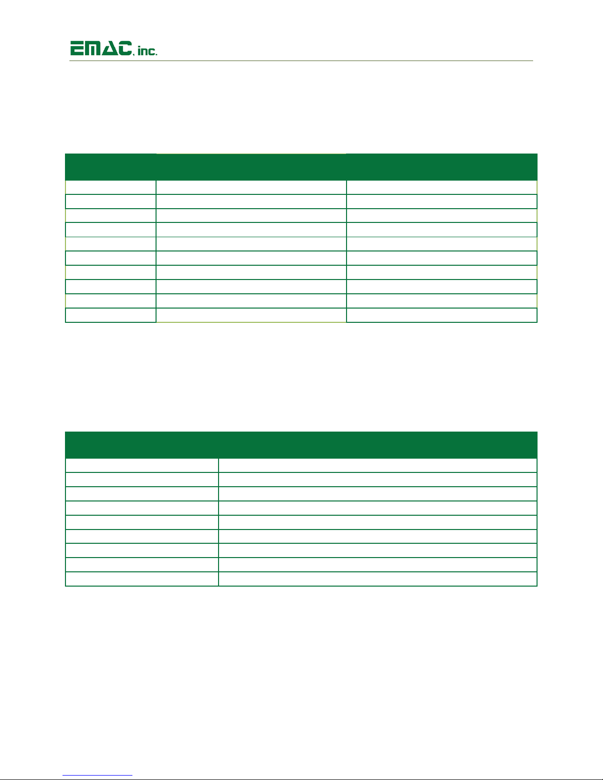
Serial Port COM B terminates to a 10-Pin header and can be configured as RS232, RS422, or
RS485 via two jumpers (JB7 & JB8). To select RS232 set jumper JB7 to 232 (this is the default).
For RS4xx set jumper JB7 to 4xx and jumper JB8 to 422 or 485 whichever is desired.
Table 5: Serial Port COM B (HDR3)
Serial Port COM C terminates to a male DB9 connector and is a RS232 port with a full
complement of handshaking lines allowing it to communicate with modems and other devices
requiring hardware flow control (Note actual number of handshake lines is determined be the
SoM)
Table 6: Serial Port COM C (JK3)
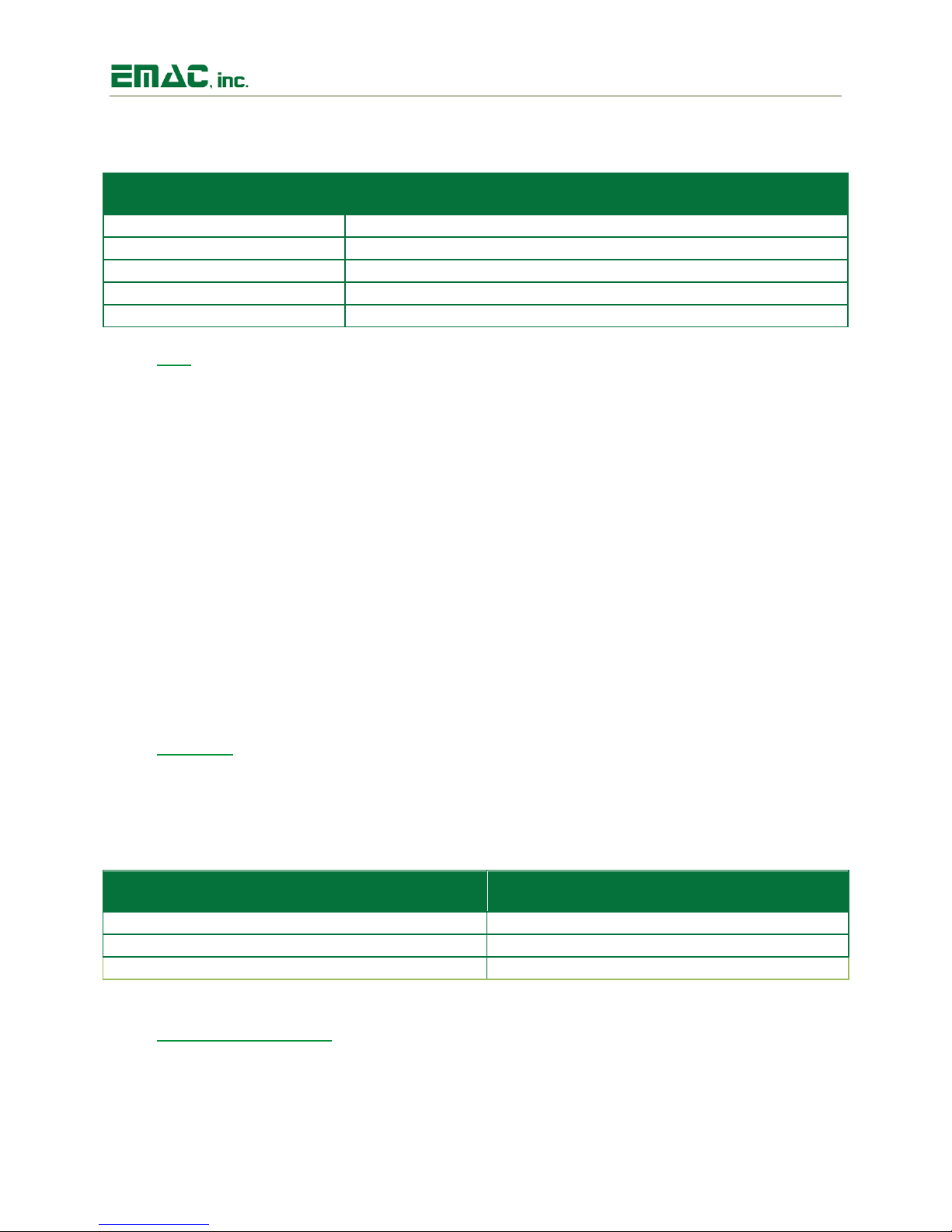
COM E is a serial console to USB device port terminating to a 5-Pin USB micro B connector. This
port offers USB to asynchronous serial date transfers and includes RTD/TXD lines. A Green
activity light is provided for the console interface and located at LD2.
Revision 1.00 © 2018 - 8 -
Page 10
SoM-112ES User Manual
Pin
Micro USB B 2.0 Connector: Description
1
PWR
2
DM (Data -)
3
DP (Data +)
4
NC
5
GND
Pin
Signal
Pin 1
GND
Pin 2
CAN_L
Pin 3
CAN_H
Table 7: Serial Port COM E (JK4)
2.6 USB
The SoM-112ES provides for 1x dual USB 2.0 Type A host ports (USB PortA1 & A2), 1x single USB 2.0
Type A host port (USB Port B), and 1x single USB Type B device port (USB Port C). Ports A1 & A2 are
provided via a USB Switch. USB HOST Port B and USB Device Port C are both provided directly from the
SOM.
The USB host ports are fused with automatically resettable Polyfuses. If a USB device tries to draw more
than 500 milliamps, the fuses will open. Once the drawing source is removed the fuses will automatically
reset.
Note: When sizing a power supply, make sure to allow for USB Device consumption. A device can
potentially draw 500mA, therefore these devices could use a total of up to 1.5 amp of power. USB ports
must be supported by the SoM for the ports to operate.
A Micro USB Connector is provided as the system serial console (COM E). This makes it easier for
modern day computers that are not equipped with a standard serial port to establish a console port
connection.
2.7 CAN Port
The SoM-112ES provides a CAN 2.0 port utilizing the TI SN65HVD232 CAN Transceiver chip. Note, the
CAN controller must be supported by the SOM in order to have CAN functionality. The CAN port is
accessible via a 3-pin header (CN2).
Table 7: Pin-out for CAN 2.0 (CN2)
2.8 MicroSD Card Socket
The SoM-112ES provides a high capacity MicroSD socket. This socket is hot-swappable and can accept a
wide variety of Flash Cards. The MicroSD card is serviced through a USB bridge device as the native SoM
SDIO port is dedicated to the Wireless module. A Red activity LED (LD3) will be lit when the Flash card is
accessed and the card should not be removed at this time. A card that is written to by the SoM-112ES
Revision 1.00 © 2018 - 9 -
Page 11

SoM-112ES User Manual
Pin
Signal
Pin
Signal
1
3P3_VCC
2
3P3_VCC
3
GND
4
EXPIO_REF
5
EXPIO_0
6
EXPIO_1
7
EXPIO_2
8
EXPIO_3
can be read by another computer using a MicroSD card reader. The MicroSD interface is compatible with
Standard and High Capacity MicroSD cards.
2.9 Audio
The SoM-112ES provides Audio Line Out and Line In capabilities through two standard audio jacks (JK1 &
JK2). Audio Jack JK1 is a stereo line level input and Audio Jack JK2 is a stereo line or headphone level
output. The processor interfaces to the Audio CODEC through its I²S interface. Volume and Balance are
controlled through software using the I²C interface lines I2C_CLK_E & I2C_DAT_E, which are accessible
via HDR1.
The CODEC is the NXP Semiconductors SGTL5000XNLA3, which is a flexible, low-power, 24-bit high
performance stereo codec with integrated headphone amplifier. It features a capless headphone design
and an internal PLL that allows inputs up to 27MHz.
2.10 Wi-Fi [Optional]
The SoM-112ES provides one Wi-Fi/Bluetooth antenna jack (JK9) which utilizes the on-board WiFi/Bluetooth Murata module (LBEE5KL1DX).
The antenna jack, (U.FL-R-SMT (10)) offers high frequency performance from DC to 6GHz, with a V.S.W.R
of 1.3 to 1.5 max. EMAC provides an antenna kit: 2.4GHz Duck Antenna RP-SMA and U.FL.(IPEX) to RPSMA male pigtail cable that plugs into the SoM’s antenna jack. Alternatively, EMAC can provide a
2.4GHz IPEX MHF flat adhesive patch antenna.
WLAN/Bluetooth Features:
2.4GHz functionality
802.11 b/g/n data rates
Interface: UART (COM D) for BT and SDIO (direct from SoM) for WLAN
IC/Firmware: Cypress/CYW4343W
Bluetooth 4.1 +EDR
2.11 I/O Expansion
The SoM-112ES provides access to a number of I/O lines on connector HDR1. The 50-pin dual row
header contains GPIO lines, SPI bus, I2C bus, A/D lines, D/A lines, PWM, I2S, interrupts, and power pins.
Signal names listed in the tables below are the SoM names as defined in the SoM 144 pin specification.
The SoM-112 is equipped with a Multi I/O chip (AD5593RBRUZ), that provides up to 8 digital input, 8
digital outputs, 8 Digital Analog Converter outputs and 8 Analog to Digital Converter inputs in any
combination. The Multi I/O can be accessed through 8 pins (5 – 12) as listed below in Table 8.
Table 8: I/O Header (HDR1)
Revision 1.00 © 2018 - 10 -
Page 12

SoM-112ES User Manual
9
EXPIO_4
10
EXPIO_5
11
EXPIO_6
12
EXPIO_7
13
GPIO_5/AD-1
14
GPIO_6/AD-2
15
GPIO_7/AD-3
16
GPIO_8/AD-4
17
GND
18
GND
19
GPIO_9/MISO
20
GND
21
GPIO_10/MOSI
22
GND
23
GPIO_11/SCK
24
GND
25
GPIO_12/CS0n
26
GND
27
GPIO_13/CS1n
28
GND
29
SPI_EXT_MISO
30
GND
31
SPI_EXT_MOSI
32
GND
33
SPI_EXT_CLK
34
GND
35
SPI_EXT_CS1n
36
GND
37
SPI_EXT_CS2n
38
GND
39
GND
40
GND
41
I2C_CLK-E
42
GPIO_1/IRQ_1
43
I2C_DAT-E
44
GPIO_14/PWM1
45
SOM_RSTO#
46
GPIO_15/PWM2
47
5V_VCC
48
5V_VCC
49
GND
50
GND
2.12 Mikrobus Expansion
The SoM-112ES provides for a MikroBus Expansion Socket. This socket has two 8-pin female headers
consisting of 3 groups of communication, 2 power groups, and 6 additional pins including PWM,
Interrupt, Analog input, reset, and chip select. There are a large number of compatible MikroBUS addon boards available in the market today that allow the end user to add functionality to development
boards. The MikroBUS module is optional and not included.
2.13 I2C
The SoM-112ES is equipped with two I2C hardware ports. One is routed to the MikroBus Expansion
Socket (SOK2) and the other is located on the Utility GPIO Header (HDR1). A TI TXS0102D voltage
translator is utilized on the I2C interface allowing a 5V or 3.3V selection via JB6 jumper.
2.14 SPI
The SoM-112ES comes equipped with two Serial Peripheral Interface buses. One is routed to the
MikroBus Expansion Socket (SOK2) and the other is located on the Utility GPIO Header (HDR1). A TI
TXB0106 Voltage Translator is utilized on the SPI interface allowing a 5V or 3.3V selection via JB5.
2.15 Status LEDs and Reset
The SoM-112ES provides a Reset Button located at PB1. Pressing this button will cause the system to
reset. A green status LED is also provided and is located at LD1.
Revision 1.00 © 2018 - 11 -
Page 13

SoM-112ES User Manual
2.16 Real-Time Clock
The SoM-112ES is equipped with an external battery (BH1) for backing up the module’s Real-Time Clock
(RTC). Drivers to access the RTC are included in the operating systems. Jumper JB1 should be placed in
the ON position in order to retain system time when powered down.
3 Software
The SoM-112ES offers a wide variety of software support from both open source and proprietary
sources. Software Board Support Packages (BSPs) and Linux Software Development Kits (SDKs) are
available for most SoM processor modules.
For more information on Linux Software Support, please visit the EMAC Wiki Software Section at:
http://wiki.emacinc.com/wiki/Product_wiki
3.1 Das U-Boot
EMAC utilizes Das U-Boot for its ARM based products. U-Boot is an open source/cross-architecture
platform independent bootloader. It supports reading and writing to the flash, auto-booting,
environmental variables, and TFTP. Das U-boot can be used to upload and run and/or reflash the OS
or to run stand-alone programs without an OS. Products are shipped with a valid MAC address
installed in flash in the protected U-boot environmental variable “ethaddr”. At boot time U-Boot
automatically stores this address in a register within the MAC, which effectively provides it to any OS
loaded after that point.
3.2 Embedded Linux
EMAC Open Embedded Linux (EMAC OE Linux) is an open source Linux distribution for use in
embedded systems. The EMAC OE Linux Build is based on the Open Embedded
(www.openembedded.org) and Yocto (www.yoctoproject.org) Linux build systems. Open Embedded
is a superior Linux distribution for embedded systems. Custom Linux builds are also available on
request.
The distribution contains everything a user could expect from a standard Linux kernel: powerful
networking features, advanced file system support, security, debugging utilities, and countless other
features.
The basic root file system includes:
Busybox
Hotplugging support
APM utilities for power management
Openssh SSH server
lighttpd HTTP server
JJFS2 or EXT4 file system with utilities
Revision 1.00 © 2018 - 12 -
Page 14

SoM-112ES User Manual
3.2.1 Linux with Xenomai Real Time Extensions
Xenomai provides real time extensions to the kernel and can be used to schedule tasks with hard
deadlines and s latencies. The Xenomai build is an additional module that can be added to the
standard Linux kernel and is available for a one-time inexpensive support/installation fee.
http://www.xenomai.org/
3.2.2 Linux Packages
EMAC provides support for many Linux Packages such as: PHP, SQLite, Perl, SNMP, DHCP Server, etc.
As with the Xenomai Package, other Packages can be added to the standard Linux file system and
are available for a one-time inexpensive support/installation fee.
3.2.3 Linux Patches
In addition to standard Embedded Linux support, EMAC has released a number of patches and
device drivers from the open source community and from internal EMAC engineering into its
standard distribution. Along with kernel patches, EMAC provides the binaries for the kernel and root
file system.
3.3 Qt Creator
Qt Creator is a cross-platform IDE (Integrated Development Environment) tailored to the needs of
Qt developers but works well for Headless applications as well. EMAC provides sample code as
projects that can be imported into Qt Creator. Qt Creator supports remote deployment and source
debugging.
http://wiki.qt.io/Main
3.4 ARM EABI Cross Compiler
The popular open source gcc compiler has a stable build for the ARM family. EMAC uses the 4.9.1
version of the ARM EABI compiler. The Embedded Linux kernel and EMAC Qt Creator projects use
this compiler for building ARM stand alone, and OS specific binaries. The EMAC Qt Creator provides
source level debugging over Ethernet or serial using gdbserver. The Linux binaries for the ARM EABI
cross compiler are available online along with the SDK. See the EMAC wiki for further information.
Revision 1.00 © 2018 - 13 -
Page 15
SoM-112ES User Manual
Pin
Signal
Pin 1
5V
Pin 2
GND
Pin 3
GND
Pin 4
12V
Pin
Signal
Pin 1
GND
Pin 2
CAN_L
Pin 3
CAN_H
Pin
Signal
Pin
Signal
1
3P3_VCC
2
3P3_VCC
3
GND
4
EXPIO_REF
5
EXPIO_0
6
EXPIO_1
7
EXPIO_2
8
EXPIO_3
9
EXPIO_4
10
EXPIO_5
11
EXPIO_6
12
EXPIO_7
13
GPIO_5/AD-1
14
GPIO_6/AD-2
15
GPIO_7/AD-3
16
GPIO_8/AD-4
17
GND
18
GND
19
GPIO_9/MISO
20
GND
21
GPIO_10/MOSI
22
GND
23
GPIO_11/SCK
24
GND
25
GPIO_12/CS0n
26
GND
27
GPIO_13/CS1n
28
GND
29
SPI_EXT_MISO
30
GND
31
SPI_EXT_MOSI
32
GND
33
SPI_EXT_CLK
34
GND
35
SPI_EXT_CS1n
36
GND
37
SPI_EXT_CS2n
38
GND
39
GND
40
GND
41
I2C_CLK-E
42
GPIO_1/IRQ_1
43
I2C_DAT-E
44
GPIO_14/PWM1
45
SOM_RSTO#
46
GPIO_15/PWM2
4 Appendix A: Connector Pinouts
4.1 4-Pin Molex Male Floppy Power Connector (CN1)
4.2 3-Pin Polarized Locking CAN Connector (CN2)
4.3 Utility GPIO Header (HDR1)
Revision 1.00 © 2018 - 14 -
Page 16
SoM-112ES User Manual
47
5V_VCC
48
5V_VCC
49
GND
50
GND
Pin
10-Pin Header: Description
1
NC 2 NC
3
COMA_RX232
4
NC
5
COMA_TX232
6
NC 7 NC 8 NC 9 GND
10
NC
Pin
RS-232 10-Pin Header: Description
RS-422/485 10-Pin Header: Description
1
NC
COMB_422/485_TX-
2
NC
NC
3
COMB_232RX
COMB_422/485_TX+
4
COMB_232_RTS
NC
5
COMB_232TX
COMB_422/485_RX+
6
COMB_232_CTS
NC
7
NC
COMB_422/485_RX-
8
NC
NC 9 GND
GND
10
NC
NC
Pin
Signal
1
GND
2
LINEIN_L
3
LINEIN_R
Pin
Signal
1
GND
2
HP_L
3
HP_R
4.4 RS-232 Serial Port COM A Header (HDR2)
4.5 RS-232/422/485 Serial Port COM B Header (HDR3)
4.6 Audio Input Jack (JK1)
4.7 Audio Output Jack (JK2)
Revision 1.00 © 2018 - 15 -
Page 17
SoM-112ES User Manual
Pin
DB9 Connector: Description
1
COMC_232_DCD
2
COMC_232_RXD
3
COMC_232_TXD
4
COMC_232_DTR
5
COMC_232_GND
6
COMC_232_DSR
7
COMC_232_RTS
8
COMC_232_CTS
9
COMC_232_RI
Pin
Micro USB B 2.0 Connector: Description
1
PWR
2
DM (Data -)
3
DP (Data +)
4
NC
5
GND
Pin
Signal
1
PWR
2
USBB_DM
3
USBB_DP
4
GND
5
CHASSIS_GND
6
CHASSIS_GND
4.8 Serial Port COM C (JK3)
4.9 Micro USB B 2.0 Console Interface Connector (JK4)
4.10 USB Host Port B (JK5)
Revision 1.00 © 2018 - 16 -
Page 18
SoM-112ES User Manual
Pin
Signal
T1
HSTA’_PWR
T2
HSTA’_DM_F
T3
HSTA’_DP_F
T4
GND
9
CHASSIS_GND
10
CHASSIS_GND
11
CHASSIS_GND
12
CHASSIS_GND
13
NC
B1
HSTB’_PWR
B2
HSTB’_DM_F
B3
HSTB’_DP_F
B4
GND
Pin
Signal
1
PWR
2
USBC_DM
3
USBC_DP
4
GND
5
CHASSIS_GND
6
CHASSIS_GND
7
CHASSIS_GND
8
CHASSIS_GND
Pin
Signal
1
ETX-
2
ETX+
3
ERX+
4
GND
5
GND
6
ERX-
7
GND
8
GND
4.11 USB Host Port A1 & A2 (JK6)
4.12 USB Device Port C (JK7)
4.13 Single Port Ethernet Connector (JK8)
Revision 1.00 © 2018 - 17 -
Page 19
SoM-112ES User Manual
Pin
Signal
1
Vin
2
GND
3
NC
Pin
Signal
1
GPIO_5/AD-1
2
SOM_RSTO#
3
SPI_EXT_CS0n
4
SPI_EXT_CLK
5
SPI_EXT_MOSI
6
SPI_EXT_MISO
7
3P3_VCC
8
GND
9
GND
10
5V_VCC
11
I2C_DAT_E
12
I2C_CLK-E
13
COMD_TXD
14
MKR_RX_GT
15
GPIO_1/IRQ_1
16
GPIO_14/PWM1
Pin
Signal
1
MSD_DAT2
2
MSD_DAT3
3
MSD_CMD
4
MSD_PWR
5
MSD_SCLK
6
GND
7
MSD_DAT0
8
MSD_DAT1
9
MSD_CDT#
10
GND
4.14 Vin Power Barrel Jack (JK10)
4.15 MikroBUS Socket (SOK2)
4.16 Micro SD Card Socket (SOK3)
Revision 1.00 © 2018 - 18 -
Page 20
SoM-112ES User Manual
Jumper
Position
Setting
Pins 1 & 2
B
Line Pulled High
Pins 2 & 3*
A
Line Pulled Low
Jumper
Position
Setting
Pins 1 & 2
B
Line Pulled High
Pins 2 & 3*
A
Line Pulled Low
Jumper
Position
Setting
Pins 1 & 2
B
Flash Disable
Pins 2 & 3*
A
Flash Enable
Jumper
Position
Setting
Pins 1 & 2
OFF
Disable Battery Backup
Pins 2 & 3*
ON
Enable Battery Backup
Jumper
Position
Setting
Pins 1 & 2
5V
5V SPI Level
Pins 2 & 3*
3.3V
3.3V SPI Level
Jumper
Position
Setting
Pins 1 & 2
5V
5V I²C Level
Pins 2 & 3*
3.3 V
3.3V I²C Level
5 Appendix B: Jumper Settings
5.1 JB1 (Boot0 Source Selection)
*Default Setting
5.2 JB2 (Boot1 Source Selection)
*Default Setting
5.3 JB3 (Flash Write Protect)
*Default Setting
5.4 JB4 (Standby Battery)
*Default Setting
5.5 JB5 (External SPI Interface Voltage)
*Default Setting
5.6 JB6 (External I2C Interface Voltage)
*Default Setting
Revision 1.00 © 2018 - 19 -
Page 21
SoM-112ES User Manual
Jumper
Position
Setting
Pins 1 & 2*
232
Select RS-232
Pins 2 & 3
4XX
Select RS-422/485 via JB8
Jumper
Position
Setting
Pins 1 & 2
485
Select RS-485
Pins 2 & 3*
422
Select RS-422
Jumper
Position
Setting
Pins 1 & 2*
A
Enable Port C
Pins 2 & 3
B
Disable Port C
5.7 JB7 (Serial Port RS-232 or RS-422/485)
*Default Setting
5.8 JB8 (Serial Port RS-422 or RS-485)
*Default Setting
5.9 JB9 (USB Device Port C Enable)
*Default Setting
Revision 1.00 © 2018 - 20 -
Page 22
SoM-112ES User Manual
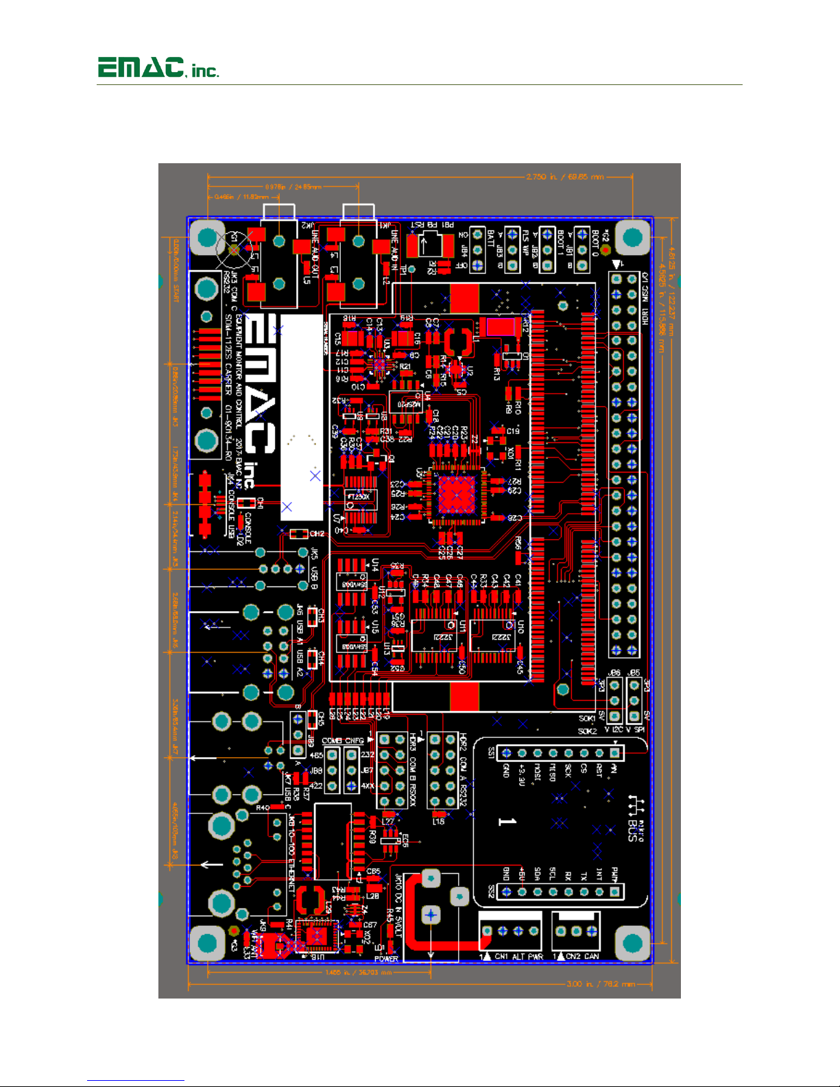
6 Appendix C: Dimensional Drawing
Revision 1.00 © 2018 - 21 -
 Loading...