

Page 1

PPC-E5
486 DX5 Panel PC
User Manual
Rev 1.13
Page 2

Contents
PPC-E5..........................................................................................................................................................................1
486 DX5 Panel PC.........................................................................................................................................................1
Contents.........................................................................................................................................................................2
General information.......................................................................................................................................................3
Features .....................................................................................................................................................................3
Standard SBC functions.............................................................................................................................................3
Local-bus flat panel/VGA interface...........................................................................................................................3
LCD...........................................................................................................................................................................3
Touchscreen...............................................................................................................................................................4
Ethernet interface.......................................................................................................................................................4
Mechanical and environmental..................................................................................................................................4
Standard Parts Inventory ...........................................................................................................................................4
PPC-E5 Configuration...................................................................................................................................................5
Jumper & Connector Descriptions.............................................................................................................................5
Powering Up the PPC-E5..........................................................................................................................................5
Ethernet......................................................................................................................................................................6
Serial Ports.................................................................................................................................................................6
Sound and LCD Contrast Controller (SLCC)............................................................................................................7
Keyboard/Mouse .......................................................................................................................................................8
Disk-On-Chip Flash Disk..........................................................................................................................................8
PPC-E5 BIOS Defaults..................................................................................................................................................9
Appendix A .................................................................................................................................................................11
Connector Pinouts....................................................................................................................................................11
Ethernet 10Base-T connector (CN2)...................................................................................................................11
Keyboard/Mouse PS/2 connector (CN3).............................................................................................................11
VGA connector (CN4).........................................................................................................................................11
LCD (CN6) (Kyocera - 8 Bit, STN, 320x240)(KCS3224ASTT-X1 LCD).........................................................11
Main Power Connector(CN8)..............................................................................................................................12
Touch Screen (CN9) (Resistive Touch Screen)...................................................................................................12
COM 3 & 4 RS-232 serial ports (CN10 &CN11)...............................................................................................12
COM 3 Optional RS-422/485 serial port (CN11)...............................................................................................13
Speaker (CN13)...................................................................................................................................................13
Floppy drive connector (CN12)...........................................................................................................................13
Appendix B..................................................................................................................................................................14
Jumper Settings .......................................................................................................................................................14
JP1 LCD Voltage............................................................................................................................................14
JP2 LCD Type................................................................................................................................................14
JP3 Serial Port (COM3 / COM4) Configuration............................................................................................14
JP4 Ethernet Settings......................................................................................................................................14
Appendix C..................................................................................................................................................................15
Mechanical drawing of PCB with dimensions.........................................................................................................15
2
Page 3

General information
Features
Ultra-compact size fully integrated Panel PC (6.1” x 4.5”)
•
On-board AMD DX5-133 (5x86-133) CPU
•
Up to 64 MB on-board EDO/Fast Page-mode DRAM
•
Local-bus SVGA display controller (LCD, EL and CRT displays).
•
On-board 16-bit Ethernet 10 BaseT interface
•
Supports M-Systems Disk-On-Chip ® 2000 Flash memory
•
On-board keyboard/mouse interface
•
Two serial ports: one RS-232, one RS-232/422/485
•
Expansion through 16 bit PC/104 connector
•
Green engine with sleep mode and low power consumption
•
+5 V and 12 V power supply required
•
Standard SBC functions
•
CPU: Embedded AMD DX5-133 (5x86-133) processor.
•
BIOS: General Software Embedded BIOS 128 KB Flash memory.
•
Chipset: Radisys R400EX.
•
System memory: One 72-pin SIMM sockets (4 MB, 8 MB, 16 MB, 32 MB, and 64 MB). Supports
FPM or EDO DRAM from 4 MB to 64 MB.
•
Serial ports: Two RS-232 ports based on a 16550 UART (one of the serial ports may be converted
to RS422/485 as a factory installed option).
•
Keyboard/mouse connector: connector supports standard PC/AT keyboard and a PS/2 mouse Via
specialized Y cable.
•
Power management: Supports power saving, APM 1.1 compliant.
•
Flash Disk: Supports M-Systems' Disk-On-Chip ® 2000 Flash disk up to 288 MB.
•
Sound: Amplified PC speaker interface with software controlled volume (speaker not included).
Local-bus flat panel/VGA interface
•
Chipset: C&T 65550
•
Display memory: 1 MB DRAM
•
Display type: Supports CRT and flat panel (EL, LCD and gas plasma flat panel) displays. Can
display CRT and flat panel simultaneously.
•
Flat panel display mode: Panel resolution supports up to 1024 x 768.
•
CRT display mode: Non-interlaced CRT monitors resolutions up to 1280 x 1024 @ 16 colors.
•
Contrast: Software controlled contrast and Backlight control.
LCD
•
Display Type: 5.7" STN Color LCD
•
Resolution: 320 x 240 @ 256K Colors
•
Dot pitch: 0.12mm x 0.36mm
•
Luminance: 160 (cd/m²)
•
Viewing Angle: 100°
•
LCD MTBF: 40,000 Hrs.
•
Backlight: Side-edge type CFL
3
Page 4

Touchscreen
•
Type: 4 Wire Analog Resistive
•
Resolution: Continuous
•
Light Transparency: 79%
•
Controller: Dynapro On board
•
Driver: WinCE, DOS, Linux
•
Durability: Over one million touches
Ethernet interface
•
Chipset: SMC 9196 10BaseT
•
Configuration: I/O & IRQ settings via jumper settings
Mechanical and environmental
•
Dimension: 6.1 " (L) x 4.5" (W)
•
Power supply voltage: +5 V (4.75 V to 5.25 V) & +12 V
•
Maximum power requirements: +5 V @ 2 A (typical)
•
Operating temperature: 32° F to 140° F (0° C to 60° C)
•
Weight: 1 lb. (approximate weight of total package)
Standard Parts Inventory
PPC-E5 Assembly with 5.7” touchscreen
•
Touchscreen inverter attached to bottom of touchscreen
•
Installed 16 meg. EDO, 72 Pin SIMM RAM stick.
•
Installed 16 meg. DOC, flash disk loaded with Operating System
•
Keyboard/Mouse Y cable
•
Two Serial Port cables
•
Video Port Cable
•
4
Page 5

PPC-E5 Configuration
Jumper & Connector Descriptions
The PPC-E5 comes factory configured. In the event that jumpers need to be verified or modified this
section provides the information required, including instructions on setting jumpers and connecting
peripherals, switches and indicators. Be sure to read all the safety precautions before you begin any
configuration procedure. See Appendix A for connector pinouts and Appendix B for Jumper Settings.
Table 1 Jumpers
Label Function
JP1 LCD Voltage
JP2 LCD Type
JP3 Serial IRQ
JP4 Ethernet Base Address and IRQ
Table 2 Connectors
Label Function
CN1 Reset
CN2 Ethernet
CN3 Keyboard/Mouse
CN4 VGA
CN5 CCFL Cathode Control Florescent
CN6 Kyocera LCD
CN7 Standard LCD (not used)
CN8 Power
CN9 Touch Screen
CN10 Com 3
CN11 Com 4
CN12 Floppy
CN13 Speaker
Powering Up the PPC-E5
The PPC-E5’s power connector (CN8) is a standard floppy, four-pin type connector commonly found on
most PC type power supplies. While the PPC-E5’s logic only requires 5 volts DC, the LCD backlight
inverter requires 12 volts DC to operate. Both of these voltages are found on the floppy type connector.
The pinout for the CN8 power connector is as follows:
Pin Signal
1 +5 V
2 GND
3 GND
4 +12 V
Remember before powering-up the PPC-E5 make sure the memory SIMM and the DOC are firmly seated
and check any cables to make sure that plugged on correctly in relation to pin 1.
Note: The PPC-E5 requires less than 2 amps typical which is not enough current to load the main
switcher in some larger PC power supplies (this can be verified with a voltmeter measuring the 5 volt
supply). If this is the case you can try to load the power supply by adding 5 volt devices, or order a
compatible power supply from EMAC.
5
Page 6

Memory - Installing DRAM (SIMMs)
You can install anywhere from 4 MB to 64 MB of on-board DRAM memory using 4, 8, 16, 32 or 64 MB 72pin SIMMs (Single In-Line Memory Modules). DRAM access time £ 60ns.
NOTE: The modules can only fit into a socket one way and their gold or silver pins must point down
•
into the SIMM socket. Make sure you are adequately grounded to avoid memory and PPC-E5
damage.
The procedure for installing SIMMs appears below. Please follow these steps carefully.
1. Ensure that all power supplies to the system are switched Off.
2. Install the SIMM stick. Install the SIMM so that its gold pins point down into the SIMM socket.
3. Slip the SIMM into the socket at a 45-degree angle and carefully fit the bottom of the card against the
connectors.
4. Gently push the SIMM into a perpendicular position until the clips on the ends of the SIMM sockets
snap into place.
5. Check to ensure that the SIMM is correctly seated and all connector contacts touch. The SIMM should
not move around in its socket.
Ethernet
The SMC 91C96 10 BaseT full duplex Ethernet chip uses a standard RJ-45 connector. It can be
connected straight to a hub, or another computer via a crossover Ethernet cable. JP4 is used to set the
Ethernet I/O address and IRQ. The default settings for this jumper block are jumpers in place at positio ns
A and B. This configuration sets the I/O address at 320H and IRQ 9. Link and Activity (Rx/Tx) LEDs are
provided to monitor network activity.
Serial Ports
The PPC-E5 is equipped with four serial ports, two which are used for on-board functionality, and two
which are available to the user. COM1 and COM2 are used on-board for the SLCC and the touchscreen
controller respectively. COM1 is initialized to 9600 and COM2 is initialized 2400 baud. Both COM1 and
COM2 use 1 start, 1 stop, 8 data bits, and no parity. The user should refrain from reconfiguring these
ports as it may disable the touchscreen and SLCC functionality. The default I/O address and IRQ for
COM1 is 3F8H using IRQ 4. The default I/O address and IRQ for COM2 is 2F8H using IRQ 3.
COM3 and COM4 are available to the user on connectors CN10 and CN11 respectively. These are
standard X86, 16550, 16 byte FIFO UARTS. The default I/O address and IRQ for COM3 is 3E8H using
IRQ 5. The default I/O address and IRQ for COM4 is 2E8H using IRQ 11.
COM3 and COM4 are both by default configured as RS232 ports. COM3 can be optionally factory
configured to an RS422/485 port.
6
Page 7

Sound and LCD Contrast Controller (SLCC)
The contrast and on-board Speaker volume are software settable via the on-board Sound an d LCD
Contrast Controller (SLCC).
Following is the description of the serial data strings that the SLCC accepts and returns. In the
description, XX or xx represent valid hexadecimal numbers in the range 00 to FF and YYYY or yyyy
represent valid hexadecimal words in the range 0000 to FFFF, and AA or aa represent a valid
hexadecimal address from 00 to 3F. The hexadecimal digits are and must be uppercase only.
Contrast
{CXX} Sets the contrast to the value XX (00 is darkest, FF is brightest).
Volume
{VXX} Sets the volume to the value XX (00 is low, FF is high).
Display
{D} Returns the current settings of the contrast and volume as {CxxVxx}.
EEPROM Write
{WAA,YYYY} Writes the 16 bit hexadecimal word YYYY to memory location AA.
Note: Location 00 is the contrast setting and 01 is the volume setting so changing these values will
change the contrast and volume on reset. Locations 2 – 5 are not currently used but are reserved for
future use so should not be used in your application.
EEPROM Read
{RAA} Returns the 16 bit hexadecimal word from location AA as {Raa,yyyy}.
Upon receiving the last character (which is '}' ) of a valid string, the SLCC returns the valid string,
including the '{' and '}'. If an invalid string is sent, nothing happens and no string is returned. The SLCC
is case sensitive and will only accept capital letters for data.
The contrast and volume settings are stored in the serial EEPROM, and these values are applied on
power-up. The EEPROM is a non-volatile storage that does not lose its data on power loss or
disconnection.
7
Page 8

Keyboard/Mouse
The PPC-E5 is equipped with a keyboard and mouse interface although in normal operation they are not
required if using the touchscreen. Both the keyboard and the mouse utilize the same PS/2 connector
(CN3) through the use of the included Y cable.
Disk-On-Chip Flash Disk
The PPC-E5 comes with a 16 Meg. DOC and 16 Meg. of RAM. The DOC and RAM can be increased to
32 Meg. Optionally.
The DOC is a solid state flash disk and as such is extremely rugged when compared to a conventional
hard drive. The DOC is a paged memory device and is mapped at segment address D000H.
Warning: Be extremely careful when installing the DOC into its socket. Plugging it in backwards
will destroy the DOC and damage the PPC-E5 rendering it inoperable! The DOC comes factory
installed and should not be removed from its socket under normal use.
8
Page 9

PPC-E5 BIOS Defaults
The PPC-E5 uses a General Software BIOS. To enter the BIOS you must press the <Del> key when
prompted. The following BIOS screen shots indicate the BIOS options and the default factory values of
each option. Note: these factory set options should not require changing.
+------------------------------------------------------------------------------+
| |
| System Bios Setup - Utility v4.2 |
| (C) 1999 General Software, Inc. All rights reserved |
+------------------------------------------------------------------------------+
| |
| |
| >Basic CMOS Configuration |
| Custom Configuration |
| Shadow Configuration |
| Reset CMOS to last known values |
| Reset CMOS to factory defaults |
| Write to CMOS and Exit |
| Exit without changing CMOS |
| |
+------------------------------------------------------------------------------+
| <Esc> to continue (no save) |
+------------------------------------------------------------------------------+
| System Bios Setup - Basic CMOS Configuration |
| (C) 1999 General Software, Inc. All rights reserved |
+---------------------------+--------------------+-----------------------------+
| DRIVE ASSIGNMENT ORDER: | Date: Apr 24, 2001 | Typematic Delay : Disabled |
| Drive A: fd0 | Time: 23 : 44 : 42 | Typematic Rate : 30 cps |
| Drive B: fd1 | NumLock: Disabled | Seek at Boot : None |
| Drive C: (None) +--------------------+ Show "Hit Del" : Enabled |
| Drive D: (None) | BOOT ORDER: | Config Box : Enabled |
| Drive E: (None) | Boot 1st: Drive C: | F1 Error Wait : Disabled |
| Drive F: (None) | Boot 2nd: (None) | Parity Checking : (Unused) |
| Drive G: (None) | Boot 3rd: (None) | Memory Test Tick : Disabled |
| Drive H: (None) | Boot 4th: (None) | Test Above 1 MB : Enabled |
| Drive I: (None) | Boot 5th: (None) | Long Memory Test : (Unused) |
| Drive J: (None) | Boot 6th: (None) | Hexadecimal Case : Upper |
| Drive K: (None) +--------------------+-----------------+-----------+
| (Loader): (Unused) | IDE DRIVE GEOMETRY: Sect Hds Cyls | Memory |
+---------------------------+ Ide 0: (Unused) | Base: |
| FLOPPY DRIVE TYPES: | Ide 1: (Unused) | 640KB |
| Floppy 0: 1.44 MB, 3.5" | Ide 2: (Unused) | Ext: |
| Floppy 1:>1.44 MB, 3.5" | Ide 3: (Unused) | 15MB |
+---------------------------+--------------------------------------+-----------+
| ^E/^X/<Tab> to select or +/- to modify |
<Esc> to return to main menu
9
Page 10

+------------------------------------------------------------------------------+
| |
| System BIOS Setup - Custom Configuration |
| (C) 1999 General Software, Inc. All rights reserved |
+---------------------------------------+--------------------------------------+
| L1 cache mode : All | DRAM burst mode : Normal |
| DRAM refresh timing : Test | Refresh the ISA bus : Disabled |
| DRAM read timing : EDO X333 | DRAM write timing : X333 |
| RAS minimum precharge time: 2.5 CLKs | CAS to RAS precharge time : 1 CLK |
| Address Setup minimum : 1 CLK | Address Hold minimum : 1 CLK |
| 1st T2 for A0000h - FFFFFh: Enabled | 1st T2 not A0000h - FFFFFh: Enabled |
| | |
| | Active display: CRT and LCD |
| | LCD Panel Type:>640x480 DSTN |
| | |
| | |
| | |
| | |
| | |
+---------------------------------------+--------------------------------------+
| ^E/^X/<Tab> to select or +/- to modify |
<Esc> to return to main menu
+------------------------------------------------------------------------------+
| |
| System BIOS Setup - Shadow/Cache Configuration |
| (C) 1999 General Software, Inc. All rights reserved |
+---------------------------------------+--------------------------------------+
| Shadowing : Chipset | Shadow 16KB ROM at C000 : Enabled |
| Shadow 16KB ROM at C400 : Enabled | Shadow 16KB ROM at C800 : Enabled |
| Shadow 16KB ROM at CC00 : Enabled | Shadow 16KB ROM at D000 : Disabled |
| Shadow 16KB ROM at D400 : Disabled | Shadow 16KB ROM at D800 : Disabled |
| Shadow 16KB ROM at DC00 : Disabled | Shadow 16KB ROM at E000 : Disabled |
| Shadow 16KB ROM at E400 : Disabled | Shadow 16KB ROM at E800 : Disabled |
| Shadow 16KB ROM at EC00 :>Disabled | Shadow 64KB ROM at F000 : Enabled |
| | |
| | |
| | |
| | |
| | |
| | |
+---------------------------------------+--------------------------------------+
| ^E/^X/<Tab> to select or +/- to modify |
<Esc> to return to main menu
10
Page 11

Appendix A
Connector Pinouts
Ethernet 10Base-T connector (CN2)
Pin Signal
1 XMT+
2 XMT3 RCV+
4N/C
5 N/C
6 RCV7N/C
8 N/C
Keyboard/Mouse PS/2 connector (CN3)
Pin Signal
1 MS CLOCK
2 KB CLOCK
3 GND
4 VCC (5V)
5 MS DATA
6 KB DATA
VGA connector (CN4)
Pin Signal Pin Signal
1 Red video 2 Key (no pin)
3 Green video 4 Sync return (GND)
5 Blue video 6 Monitor ID (not used)
7 Not used 8 Monitor ID (not used)
9 GND 10 Horizontal sync
11 Red return (GND) 12 Vertical sync
13 Green return (GND) 14 NC
15 Blue return (GND) 16 NC
LCD (CN6) (Kyocera - 8 Bit, STN, 320x240)(KCS3224ASTT-X1 LCD)
Pin Signal
1FRM
2LOAD
3CP
4DISP
5VDD
6 VSS
7 VEE
8D7
9D6
10 D5
11 D4
12 D3
13 D2
14 D1
15 D0
11
Page 12

LCD connector (CN7)
Pin Signal Pin Signal
1 +12 V DC 2 +12 V DC
3 GND 4 GND
5 Vcc(+5V/+3.3V) 6 Vcc(+5V/+3.3V)
7 ENA VEE 8 GND
9 P0 10 P1
11 P2 12 P3
13 P4 14 P5
15 P6 16 P7
17 P8 18 P9
19 P10 20 P11
21 P12 22 P13
23 P14 24 P15
25 P16 26 P17
27 P18 28 P19
29 P20 30 P21
31 P22 32 P23
33 GND 34 GND
35 SHFCLK 36 FLM (V SYS)
37 M 38 LP (H SYS)
39 GND 40 ENABKL
41 NC 42 SHFCLK /ASHFCLK
43 NC 44 NC
Main Power Connector(CN8)
Pin Signal
1 +5 V
2 GND
3 GND
4 +12 V
Touch Screen (CN9) (Resistive Touch Screen)
Pin Singnal
1 Horizontal Resistance
2 Vertical Resistance
3 Horizontal Resistance
4 Vertical Resistance
COM 3 & 4 RS-232 serial ports (CN10 &CN11)
Pin Signal DB9 Pin #
1 DCD DCD
2 DSR RxD
3 RxD TxD
4 RTS DTR
5 TxD GND
6 CTS DSR
7 DTR RTS
8 RI CTS
9 GND RI
10 NC --
12
Page 13

COM 3 Optional RS-422/485 serial port (CN11)
Pin Signal DB9 Pin #
1 NC NC
2 NC Tx+(A)
3 Tx+(A) Tx-(B)
4 Rx+(A) NC
5 Tx-(B) NC
6 Rx-(B) NC
7 NC Rx+(A)
8 NC Rx-(B)
9 GND NC
10 NC --
Speaker (CN13)
Pin Signal
1 Speaker +
2NC
3 Speaker -
Floppy drive connector (CN12)
Pin Signal Pin Signal
1 GND 2 DENSITY SELECT
3 GND 4 N/C
5 GND 6 N/C
7 GND 8 INDEX
9 GND 10 MOTOR 0
11 GND 12 DRIVE SELECT 1
13 GND 14 DRIVE SELECT 0
15 GND 16 MOTOR 1
17 GND 18 DIRECTION
19 GND 20 STEP
21 GND 22 WRITE DATA
23 GND 24 WRITE GATE
25 GND 26 TRACK 0
27 GND 28 WRITE PROTECT
29 GND 30 READ DATA
31 GND 32 HEAD SELECT
33 GND 34 DISK CHANGE
13
Page 14

Appendix B
Jumper Settings
JP1 LCD Voltage
Jumper Setting
No Jumper Not Available
Pins 1 & 2* 5v LCD output
Pins 2 & 3 3V LCD output
* Default setting, for Kyocera LCD.
JP2 LCD Type
Jumper Setting
Pins 1 & 2 Special STN
Pins 2 & 3* TFT and Standard STN displays
* Default setting, should work for most LCD screens
JP3 Serial Port (COM3 / COM4) Configuration
Row of jumpers closest to ABC letters
Jumper Shorting AB* Com 4 on IRQ 11
Jumper Shorting BC Com 4 on IRQ 7
Second row of jumpers next to the above jumpers
Jumper shorting AB* Com 3 on IRQ 5
Jumper Shorting BC Com 3 on IRQ 9
* Default Setting
JP4 Ethernet Settings
Config # I/O IRQ ROM Media Jumper
0 0x300 5 No 10bT A B C
1* 0x320 9 No 10bT A B
2 0x340 11 No 10bT A C
3 0x360 7 No 10bT A
4NA
5NA
6NA
7 0x300 5 yes 10bT none
Note: Config #7 is for Remote Boot and expects a 16kb boot ROM at address CC000. This can be
accomplished by putting the boot ROM in the DOC socket.
* Default setting
14
Page 15
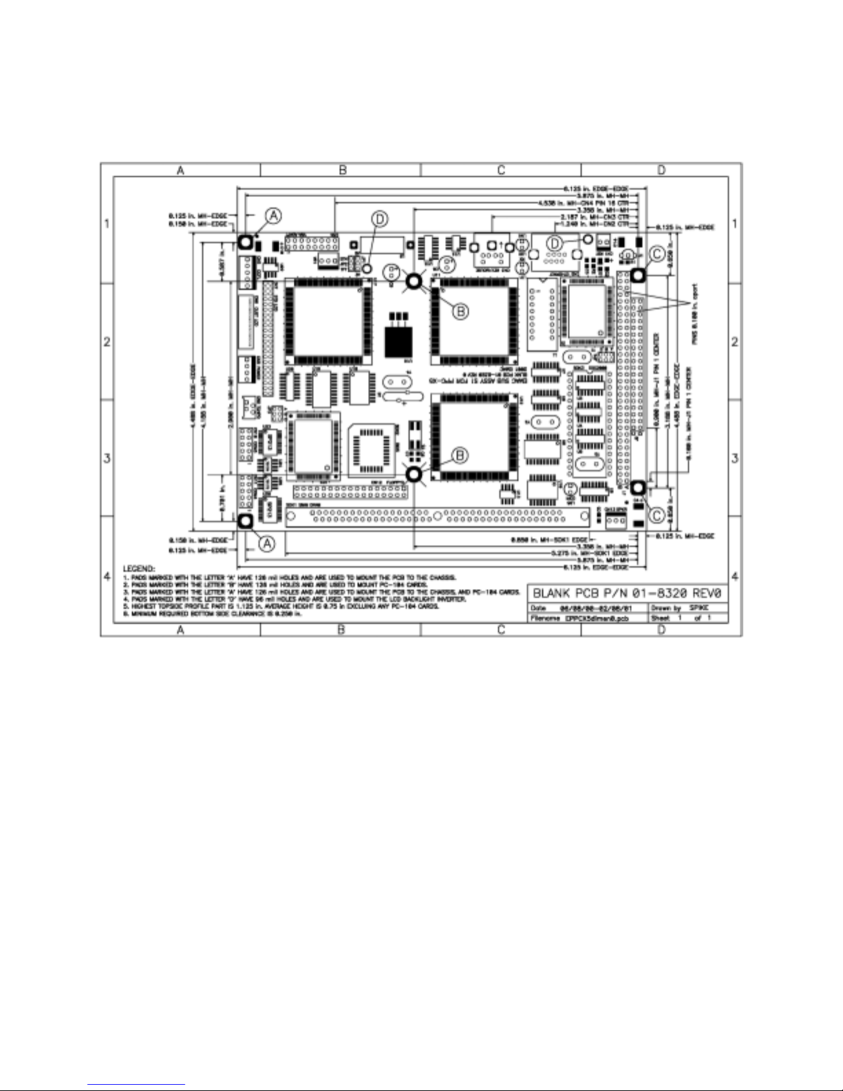
Appendix C
Mechanical drawing of PCB with dimensions
15
 Loading...