

Page 1

PPC-E10
ARM Cortex A8 Panel PC
User Manual
REV. 2.0
Copyright 2014,
EMAC, Inc.
Page 2

Table of Contents
PPC-E10 Product Summary .................................................................................................................... 3
1.1 Features ........................................................................................................................................................................ 3
1.2 Standard PPC Specifications ........................................................................................................................................ 4
1.3 Description ................................................................................................................................................................... 5
PPC-E10 Product Details ......................................................................................................................... 6
1.4 Jumper Configuration & Connector Descriptions ........................................................................................................ 6
1.5 Power Connectors ........................................................................................................................................................ 6
1.6 Ethernet ........................................................................................................................................................................ 7
1.7 Serial Ports ................................................................................................................................................................... 7
1.8 USB Host Ports ............................................................................................................................................................ 8
1.9 Audio Port .................................................................................................................................................................... 9
1.10 LCD Brightness Control .............................................................................................................................................. 9
1.11 MicroSD Card Socket .................................................................................................................................................. 9
1.12 Keyboard/Mouse .......................................................................................................................................................... 9
1.13 Analog Inputs ............................................................................................................................................................... 9
1.14 I/O Expansion ............................................................................................................................................................ 10
1.15 Real-Time Clock ........................................................................................................................................................ 10
1.16 Status LEDs and Reset ............................................................................................................................................... 10
Software ................................................................................................................................................... 11
1.17 Introduction ................................................................................................................................................................ 11
1.18 EMAC Support Wiki ................................................................................................................................................. 11
1.19 U-Boot Bootloader ..................................................................................................................................................... 11
1.20 Linux Tools ................................................................................................................................................................ 11
1.21 Linux Operating System ............................................................................................................................................ 12
1.22 Android Operating System ........................................................................................................................................ 13
Appendix A: Connector Pinouts ............................................................................................................. 14
1.23 Ethernet 10/100 Base-T connector (JK2) ................................................................................................................... 14
1.24 USB Connector (JK3, JK4, HDR5) ........................................................................................................................... 14
1.25 Power Jack (JK1) ....................................................................................................................................................... 14
1.26 Power Connector (J1) ................................................................................................................................................ 15
1.27 MicroSD Socket (SOK1) ........................................................................................................................................... 15
1.28 TTL LCD/Touch/Backlight (CN6) ............................................................................................................................ 15
1.29 LVDS LCD/Touch/Backlight (HDR6) ...................................................................................................................... 16
1.30 PCD-E12 Expansion connector (ABJ1) ..................................................................................................................... 16
1.31 COMA RS-232 serial port (CN2) .............................................................................................................................. 16
1.32 COMB RS-232 Serial Port (HDR3) .......................................................................................................................... 17
1.33 COMC RS-232/422/485 Serial Port (HDR4) ........................................................................................................... 17
1.34 COMD RS-232 Serial Port (HDR2) ......................................................................................................................... 17
1.35 Misc. General Purpose I/O (HDR1) ........................................................................................................................... 18
1.36 Touch Screen Connector (CN1) ................................................................................................................................. 18
1.37 Touch Screen Connector (CN3) ................................................................................................................................. 18
1.38 LCD Backlight Connector (CN4) .............................................................................................................................. 18
Appendix B: Jumper Settings ................................................................................................................. 19
Appendix C: Mechanical drawing of Mounting Plate with dimensions .............................................. 20
ENG-00178-20P-PPC-E10_User_Manual.docdoc -1- Rev 2.0 © 2014 EMAC, Inc.
Page 3

Disclaimer
EMAC Inc. does not assume any liability arising out of the application or use of any of its products or designs.
Products designed or distributed by EMAC Inc. are not intended for, or authorized to be used in, applications such
as life support systems or for any other use in which the failure of the product could potentially result in personal
injury, death or property damage.
If EMAC Inc. products are used in any of the aforementioned unintended or unauthorized applications, Purchaser
shall indemnify and hold EMAC Inc. and its employees and officers harmless against all claims, costs, damages,
expenses, and attorney fees that may directly or indirectly arise out of any claim of personal injury, death or
property damage associated with such unintended or unauthorized use, even if it is alleged that EMAC Inc. was
negligent in the design or manufacture of the product.
EMAC Inc. reserves the right to make changes to any products with the intent to improve overall quality, without
further notification.
ENG-00178-20P-PPC-E10_User_Manual.docdoc -2- Rev 2.0 © 2014 EMAC, Inc.
Page 4

PPC-E10 Product Summary
1.1 Features
Texas Instruments AM3517 600Mhz ARM Cortex A8 based Processor
Inexpensive Open-Frame Design
Up to 512 MB of SDRAM (256 MB Standard)
2GB eMMC Flash
Battery backed Real Time Clock
10/100BaseT Ethernet with on-board PHY
3 RS232 & 1 RS232/422/485 Port
1 USB 2.0 (High Speed) Host ports (USB 1.1 Compatibility)
1 USB 2.0 (High Speed) OTG Host/Device port
1 CAN 2.0B Port
1 Micro SD Flash Card Socket
1 I2S Audio port with Line-In/Line-Out
Timer/Counters and Pulse Width Modulation (PWM) ports
1 Channel 12-bit Analog-to-Digital converter
Operating Voltage of 12 to 26 Vdc.
Graphic LCD Interface with 2D/3D acceleration
WVGA (1024x600) Resolution with LED Backlight
Analog Resistive Touchscreen and Software Controlled Backlight On/Off & Brightness
JTAG for debug, including real-time trace
FREE Eclipse IDE or QT Creator with GCC & GDB development tools for Linux
Android Available
ENG-00178-20P-PPC-E10_User_Manual.docdoc -3- Rev 2.0 © 2014 EMAC, Inc.
Page 5

1.2 Standard PPC Specifications
CPU: Fanless ARM Cortex A8 600Mhz Processor
Flash: 2GB of eMMC Flash.
RAM: 256MB of DDR2 RAM.
Video: 1024 x 600 WVGA @ 256K Colors
Touchscreen: 12-Bit, 4 wire analog resistive Touchscreen
Flash Disk: 1 Micro SD flash card socket
System Reset: Processor Internal Reset Management with External Reset Button provision
RTC: Battery backed Real Time Clock/Calendar.
Timers: 11, general purpose Timers, & Counter/PWM
Watchdog Timer: 2 Internal Watchdog Timers
Analog I/O: 1 channel, 12-bit Analog-to-Digital converter (ADC)
GPIO: 16 Programmable 3.3V I/O lines
Serial Interfaces
UARTS: 3 serial RS232 serial ports with handshaking & 1 RS232/422/485 with Auto RS485
SPI: High-Speed SPI port with Chip Selects.
I2C: I2C port
Audio: I2S Synchronous Serial Controller with Stereo Line In/Out
CAN: CAN 2.0B Port
USB: 2 USB 2.0 (High Speed) Host ports
1 USB 2.0 (High Speed) OTG Host/Device port
LCD
Display Type: 10" TFT Color LCD
Resolution: 1024 x 600 WVGA @ 256K Colors
Dot pitch: 0.19mm x 0.19mm
Luminance: 330 (cd/m²)
Viewing Angle: 55°
Brightness: Software controlled
Backlight: White LED (33 LEDS)
Touchscreen
Type: 4 Wire Analog Resistive
Resolution: Continuous
Controller: Built-In
Driver: Linux
Durability: Over one million touches
Ethernet interface
Ethernet MAC: Built-In
Ethernet PHY: Micrel KSZ8041
Ethernet Type: 10/100 Base-T Ethernet
Ethernet Interface: On-Board RJ-45 connector
ENG-00178-20P-PPC-E10_User_Manual.docdoc -4- Rev 2.0 © 2014 EMAC, Inc.
Page 6

Solid-state Flash Disk
Supports: External Removable SDIO SDHC/MMC interface up to 32+ GB Flash Disk
Mechanical and environmental
Power Supply Voltage: +12 to +26 Vdc.
Power Consumption: typical ~250 ma. @ 24 Vdc.
Operating Temperature: 0 ~ 60° C (32 ~ 140° F; LCD Constraint)
Standard Parts Inventory
PPC-E10 Assembly with 10” Touchscreen LCD
Stainless Steel Mounting Bracket
Resident on-board flash disk loaded with Operating System
Three Serial Port cables
CD ROM with manuals and drivers
1.3 Description
The PPC-E10 is a rugged embedded Open Frame Panel PC (PPC). The PPC-E10 utilizes a modular System on Module
(SoM) design which extends the longevity and flexibility of the PPC-E10.
The PPC-E10 is comprised of a Processor Module and a Carrier board in which the Module plugs into. If more memory
is required or speed is required a different pin compatible Module offering these features can be inserted into the Carrier
board in place of the standard Module that is provided. Additionally, if the processor or memory go End Of Life another
processor Module can be utilized extending the life of the product.
ENG-00178-20P-PPC-E10_User_Manual.docdoc -5- Rev 2.0 © 2014 EMAC, Inc.
Page 7

Label
Function
Default
JB1
Boot0 Source Selection
Position B
JB2
Boot1 Source Selection
Position A
JB3
Resident Flash Write Protect (GPIO_62)
Position A
JB4
RTC Battery ON/OFF
Off
JB5
Serial Port RS422/485 Tx Enable
422
JB6
Serial Port RS232 or 422/485 Mode
232
Label
Function
CN1
7” Touch Screen Connector
CN2
Serial Port COM A
CN3
10” Touch Screen Connector
CN4
7” LCD Backlight Connector
CN6
7” LCD Data Connector
J1
Vin Locking Connector
JK1
Vin Power Barrel Jack
JK2
Ethernet
JK3
USB Host Port A & Port B
JK4
USB OTG Port C
JK5
Audio Input Jack
JK6
Audio Output Jack
HDR1
Misc. I/O Connector
HDR2
Serial Port COM D
HDR3
Serial Port COM B
HDR4
Serial Port COM C
HDR5
Bulkhead USB Connector Port A & B
HDR6
LVDS & Touch Signal Connector
SOK1
MicroSD Card Socket
SOK2
200 pin SOM Socket
ABJ1
PCD-E12 Expansion Module Connector
PPC-E10 Product Details
1.4 Jumper Configuration & Connector Descriptions
The PPC-E10 comes factory configured. In the event that jumpers need to be verified or modified this section
provides the information required, including instructions on setting jumpers and connecting peripherals, switches
and indicators. Be sure to read all the safety precautions before you begin any configuration procedure. See
Appendix A for connector pinouts and Appendix B for Jumper Setting descriptions.
Table 1: Jumpers
Table 2: Connectors
1.5 Power Connectors
The PPC-E10 provides two power connectors. J1 is an AMP/Tyco locking power connector (part# 640445-3),
three-pin type connector that mates with TE Connectivity part# 647402-3 power connector using crimp pins part#
3-647406-1. Using this power input provides for a more rugged/industrial locking connection. JK1 is a standard
5.5mm barrel jack with an inner diameter of 2.1mm with a center V+ connection. This jack allows for easy
connection to a wall mount power supply (EMAC part number PER-PWR-00035). The PPC-E10’s power input
uses a switching regulator and allows a voltage input of +12Vdc to +26Vdc.
ENG-00178-20P-PPC-E10_User_Manual.docdoc -6- Rev 2.0 © 2014 EMAC, Inc.
Page 8

#
Pin Description for DB9
Connector
1
DCD
2
RxD
3
TxD
4
DTR
5
GND
6
DSR
7
RTS
8
CTS
9
RI
10
Shield
The pinout for the J1 power connector is as follows:
Pin Signal
1 +Vin (+12Vdc to 26Vdc)
2 Chassis GND
3 System GND
Before powering up the PPC-E10, jumper JB1 is in the “B” position
1.6 Ethernet
The PPC-E10 provides 10/100 Base-T full duplex Ethernet and uses a standard RJ-45 connector (JK2). It can be
connected straight to a hub, or another computer via a crossover Ethernet cable. The Ethernet MAC & PHY are
integrated into the SoM processor module. Activity and Link LEDs are integrated into the RJ45 connector.
1.7 Serial Ports
The PPC-E10 is equipped with four serial ports, one of which terminates to a male DB9 and the other three which
terminate to 10pin header connectors (see table 2, 3, & 4 below). Three 10-pin header to male DB9 connector
cables are provided, giving easy access to these ports. Baud Rate, stop bits, etc. are all programmable for each
port via software.
COM A is an RS232 compatible port with a full complement of handshaking lines (through the use of GPIO lines)
allowing it to communicate with modems and other devices requiring hardware flow control.
COM B is an RS232 port. This port offers no handshake lines.
COM C can be configured to RS232, RS422, and RS485 via 2 jumpers. To select RS232 set jumper JB6 to 232
(this is the default). For RS422 set jumper JB6 to 4xx and jumper JB5 to 485. To select RS485, set jumper JB6 to
4xx and jumper JB5 to 422.
When using COM C in the RS422/485 mode, a terminating resistor (~120 Ohm) is recommended on the two far
ends of the network.
COM D is an RS232 port. This port offers no handshake lines.
Table 1 (COM A Pinout)
ENG-00178-20P-PPC-E10_User_Manual.docdoc -7- Rev 2.0 © 2014 EMAC, Inc.
Page 9

#
Pin Description for 10Pin Header
Pin Description for DB9
Connector
1
NC
NC 2 NC
RxD
3
RxD
TxD
4
NC
NC
5
TxD
GND
6
NC
NC 7 NC
NC 8 NC
NC
9
GND
NC
10
NC
-
#
Pin Description for 10-Pin
Header
Pin Description for DB9
Connector
1
422/485 TX-
422/485 TX-
2
NC
232 RX, 422/485 TX+
3
232 RX, 422/485 TX+
232 TX, 422/485 RX+
4
RTS
422/485 RX-
5
232 TX, 422/485 RX+
GND
6
CTS
NC
7
422/485 RX-
RTS
8
NC
CTS
9
GND
NC
10
NC
-
#
Pin Description for 10Pin Header
Pin Description for DB9
Connector
1
NC
NC
2
NC
RxD
3
RxD
TxD
4
NC
NC 5 TxD
GND
6
NC
NC
7
NC
NC
8
NC
NC 9 GND
NC
10
NC
-
Table 2 (COM B Pinout)
Table 3 (COM C Pinout)
Table 4 (COM D Pinout)
1.8 USB Host Ports
The PPC-E10 provides two, USB 2.0 (USB PortA & PortB) high speed host ports (JK3). USB PortA and PortB
can also be accessed from the bulkhead connector (HDR5). EMAC can provide a cable (CAB-40-004) to access
these ports.
In addition to the two USB Host ports, the PPC-E10 provides a USB On-The-Go (OTG) port. This port can be
used as either a USB Host or USB Device port.
All of the USB ports are equipped with 500mA re-settable Polyfuses. If a USB Device tries to draw more than
500mA from the port, the fuse will open until the device is unplugged or its current requirement is reduced. There
is no software provision for shutting down power to the Ports or detecting when a port is drawing too much
current.
ENG-00178-20P-PPC-E10_User_Manual.docdoc -8- Rev 2.0 © 2014 EMAC, Inc.
Page 10

Note: When sizing a power supply, make sure to allow for USB Device consumption. A device can potentially
draw 500mA, therefore these devices could use a total of over 1 amp of power.
1.9 Audio Port
The PPC-E10 provides Audio Line Out and Line In capability through two standard audio jacks (JK5 & JK6).
Audio Jack JK5 is stereo line level input and Audio Jack JK6 is stereo line level output. The processor interfaces
to the Audio CODEC through its I2S interface. Command control of the CODEC is done using the processor’s SPI
interface. The CODEC is the Cirrus CS4271, which is a high performance 24-bit Stereo CODEC offering superior
sound quality.
Both the input and output are line level. You will probably not be able to drive an unamplified speaker although
standard headphones will work. Likewise, an un-amplified microphone probably will not work as an input although
the line out of a CD player will work.
1.10 LCD Brightness Control
The PPC-E10 offers LCD brightness control that can change the brightness of the LCD via software. The LCD
utilizes LED backlighting. The board provides the backlight with approximately 10 volts at about 220mA. The
processor provides a PWM (SoM pin# 85) that is used to drive the LCD backlight. Changing the duty-cycle of the
PWM directly affects the brightness of the LCD. In addition, the backlight can be turned off or on via SoM port line
GPIO0 (SoM pin#114). This allows screensaver software to automatically turn off the backlight when the unit is
not being used and to automatically turn it back on when the touchscreen is touched.
1.11 MicroSD Card Socket
The PPC-E10 provides a high capacity MicroSD socket. The socket is resident on the Carrier and accessible from
the board coast line. The socket is hot-swappable and can accept a wide variety of Flash Cards. A green activity
light (LED LD3) is located towards the left side of the socket on the Carrier. When the processor is accessing the
Flash card this LED will be lit and the card should not be removed at this time. A card that is written to by the
PPC-E10 can be read by another computer using an MicroSD card reader. The MicroSD interface is compatible
with Standard and High Capacity MicroSD cards
1.12 Keyboard/Mouse
The PPC-E10 does not provide a PS/2 type keyboard/mouse interface. However, a USB keyboard and mouse
can be used if required.
1.13 Analog Inputs
A 12-Bit analog input is available on HDR1 (see table 5 below) and is labeled as analog_04.
ENG-00178-20P-PPC-E10_User_Manual.docdoc -9- Rev 2.0 © 2014 EMAC, Inc.
Page 11

Pin
Signal
Pin
Signal
1
3.3V
2
3.3V
3
GPIO1
4
GPIO4
5
GPIO2
6
GPIO5
7
GPIO3
8
GPIO6
9
INT0
10
GPIO7
11
INT1
12
GND
13
OSC0
14
GND
15
OSC1
16
GND
17
ADC4
18
GND
19
NC
20
GND
21
NC
22
GND
23
NC
24
GND
25
SPI_MISO
26
GND
27
SPI_MOSI
28
GND
29
31
33
35
37
39
41
43
SPI_CLK
SPI_CS3
SPI_CS1
I2C_DAT
I2C_CLK
*SOM_RSTOUT
5V_VCC
GND
30
32
34
36
38
40
42
44
GND
GND
GND
GND
GND
GND
5V_VCC
GND
1.14 I/O Expansion
The Processor used by the PPC-E10 provides a number of unused I/O lines. The PPC-E10 provides access to
these lines on connector HDR1. This 44-pin dual row header contains GPIO lines, SPI bus, I2C bus, A/D,
interrupts and power pins. Signal names listed in the table below are the SoM names as defined in the SoM 200
pin specification.
1.15 Real-Time Clock
The PPC-E10 is equipped with an external battery for backing up the module’s Real-Time Clock (RTC). Drivers to
access the RTC are included in the operating systems. Jumper JB4 should be placed in the ON position in order
to retain system time when powered down.
1.16 Status LEDs and Reset
The PPC-E10 provides two status LEDs, LD1 (Green) and LD2 (Red). These can be controlled independently via
software (GPIO13 & GPIO12 respectively). LD1 and LD2 are located just to the left of the SD/MMC socket.
Also provided is a Reset Button (PB1). Pressing this button will cause the system to reset.
ENG-00178-20P-PPC-E10_User_Manual.docdoc -10- Rev 2.0 © 2014 EMAC, Inc.
Page 12

Software
1.17 Introduction
The PPC-E10 can be programmed in a variety of languages and utilize a variety of Operating Systems. There are
a number of free compilers, interpreters, and assemblers available allowing the PPC-E10 to be programmed in C,
Java or Assembly languages. EMAC has Board Support Packages available for Linux, Xenomai Real Time Linux
and Windows CE. For more information on these particular Operating Systems, contact EMAC, Inc.
1.18 EMAC Support Wiki
EMAC provides a Support Wiki to provide additional Linux information for our customers. To access the Wiki go
to: http://wiki.emacinc.com/wiki/Main_Page
1.19 U-Boot Bootloader
The PPC-E10 is distributed with Das U-Boot installed. U-Boot is an open source/cross architecture platform
independent bootloader. It supports reading and writing to the flash, auto-booting, environmental variables, and
tftp. Das U-boot can be used to upload and run and/or reflash the OS on the SoM-3517M without the use of a
JTAG cable, or to run stand-alone programs without an OS. SoM-3517M modules are shipped with a valid MAC
address installed in flash in the protected ethaddr environmental variable of U-Boot. At boot time U-Boot
automatically stores this address in a register within the MAC, which effectively provides it to any OS loaded after
that point.
1.20 Linux Tools
1.20.1 Eclipse
EMAC provides sample code for the PPC-E10 as CDT projects within the free Eclipse IDE. Eclipse is a powerful
open-source Java based IDE. It has plug-ins for development and debugging in Java and C, as well as several
other languages.
http://www.eclipse.org/
EMAC offers a free download of Eclipse pre-integrated with the CDT plug-in and plug-ins for remote debugging,
SVN, and other purposes. Eclipse requires the Java Runtime Environment to be installed on the development
system. Currently EMAC only supports the use of Eclipse under the Linux environment for the PPC-E10. The
Eclipse environment and JRE for Linux are available online along with user manuals.
ftp://ftp.emacinc.com/PCSBC/Development_Kits/EMAC_Open_Tools/
1.20.2 Eclipse CDT plug-in
The Eclipse CDT plug-in provides a powerful graphical IDE for C development. This plug-in relies on GNU Make
to build its files, so its projects are highly portable to other IDE’s (or lack of them completely). It also offers a MI
based debugger, for plugging into newer gdbs.
http://www.eclipse.org/cdt/
1.20.3 ARM EABI Cross Compiler
The popular open source gcc compiler has a stable build for the ARM family. The Embedded Linux kernel and
EMAC Eclipse CDT projects use this compiler for building ARM stand alone, and OS specific binaries. The EMAC
Eclipse SDK provides source level debugging over either the JTAG port or over Ethernet or serial using
gdbserver. The Linux binaries for the ARM EABI cross compiler are available online along with the SDK for the
PPC-E10 at the following location.
ftp://ftp.emacinc.com/Controllers/Development_Kits/EMAC_Open_Tools/Linux/
ENG-00178-20P-PPC-E10_User_Manual.docdoc -11- Rev 2.0 © 2014 EMAC, Inc.
Page 13

1.20.4 Qt Creator
EMAC can optionally provide Qt Creator in place of Eclipse. Qt Creator is a cross-platform IDE (integrated
development environment) tailored to the needs of Qt developers but can be used without the use of QT. For
more information go to: http://qt-project.org/wiki/Category:Tools::QtCreator
1.20.5 EMAC’s LDC
EMAC also offers a pre-configured Linux Development Computer (LDC) which allows the user to hit the ground
running and not have to worry about setting up Linux Machine with the Eclipse development environment. This is
an ideal solution for Windows users who are not familiar with Embedded Linux.
http://www.emacinc.com/products/ldc
1.21 Linux Operating System
1.21.1 Embedded Linux
EMAC Open Embedded Linux is an open source Linux distribution for use in embedded systems. The current
PPC-E10 build uses a Linux 3.2 or newer kernel.
The distribution contains everything a user could expect from a standard Linux kernel, powerful networking
features, advanced file system support, security, debugging utilities, and countless other features. The PPC-E10
will work out of the box with EMAC’s Embedded Linux distribution, and EMAC provides the most up to date
distribution via FTPSVN.
The Bootloader / Linux Console Port defaults to:
COMB (HDR3)
115200 Baud
N-8-1
No Handshaking
1.21.2 Linux with Xenomai Real Time Extensions
Xenomai provides real time extensions to the kernel and can be used to schedule tasks with hard deadlines and
µs latencies. The Xenomai build is an additional module that can be added to the standard Linux kernel and is
available for a one-time inexpensive support/installation fee.
http://www.xenomai.org/
1.21.3 Qt Graphic User Interface Framework
EMAC can optionally provide Qt in place of X Windows as the graphic user interface. Qt is a cross-platform
application and UI framework for developers using C++ or QML, a CSS & JavaScript like language. Qt Creator is
the supporting Qt IDE. For more information on Qt go to: http://qt-project.org/
1.21.4 Linux Modules
EMAC provides support for many Linux modules such as: Lighttpd Web Server, PHP, SQLite, Perl, SNMP, DHCP
Server, etc. As with the Xenomai module, other modules can be added to the standard Linux filesystem and are
available for a one-time inexpensive support/installation fee.
1.21.5 Linux 2.6 Public Repository
EMAC Linux 4.0 Distribution integrates a number of kernel patches and device drivers from the open source
community along with support for EMAC engineered products. Currently, the kernel for the SoM-3517M is
available via our public SVN repository.
https://svn.emacinc.com/public/linux-2.6.30-at91/trunk/
Along with kernel source, EMAC provides the binaries for the kernel and root file system.
ftp://ftp.emacinc.com/Controllers/SoM/SoM-3517M/Software/images/
ENG-00178-20P-PPC-E10_User_Manual.docdoc -12- Rev 2.0 © 2014 EMAC, Inc.
Page 14

1.21.6 Open Embedded
The Linux build for the PPC-E10 is based on the Open Embedded (www.openembedded.org) Linux build system.
The current kernel is Linux 2.6.30 or higher patched to support the PPC-E10. Open Embedded is a superior Linux
distribution for embedded systems. Custom Linux builds are also available on request.
The basic root filesystem includes:
Busybox 1.13 or higher
Hotplugging support
APM utilities for power management
Open BSD SSH server
Telnet/FTP support running under inetd
busybox-httpd HTTP server
JFFS2 filesystem with utilities
1.22 Android Operating System
EMAC offers a preconfigured version of Android 2.1 for the PPC-E10. Android consists of a kernel based on the
Linux kernel, with middleware, libraries and APIs written in C and application software running on an application
framework which includes Java-compatible libraries based on Apache Harmony. Android uses the Dalvik virtual
machine with just-in-time compilation to run compiled Java code. Android has a large community of developers
writing applications ("apps") that extend the functionality of the devices. Developers write primarily in a
customized version of Java. Note: Android requires significant resources in order to run. The PPC-E10 will run
Android but it will be sluggish.
ENG-00178-20P-PPC-E10_User_Manual.docdoc -13- Rev 2.0 © 2014 EMAC, Inc.
Page 15

Appendix A: Connector Pinouts
1.23 Ethernet 10/100 Base-T connector (JK2)
Pin Signal
1 XMT+
2 XMT3 RCV+
4 N/C
5 N/C
6 RCV7 N/C
8 N/C
1.24 USB Connector (JK3, JK4, HDR5)
1.24.1 PortA (JK3 - Host)
Pin Signal
1 USB_PWR (5Vdc)
2 USB_Data-
3 USB_Data+
4 GND
1.24.2 PortB (JK3 - Host)
Pin Signal
1 USB_PWR (5Vdc)
2 USB_Data-
3 USB_Data+
4 GND
1.24.3 PortC (JK4 - OTG)
Pin Signal
1 USB_VBUS
2 USB_Data-
3 USB_Data+
4 USB_ID
4 GND
1.24.4 PortA/B (HDR5)
Pin Signal Pin Signal
1 USB_PWR_A 2 USB_PWR_B
3 USB_HOSTA- 4 USB_HOSTB-
5 USB_HOSTA+ 6 USB_HOSTB+
7 GND 8 GND
9 Chassis GND 10 NC
1.25 Power Jack (JK1)
Pin Signal
Center 5V DC
Barrel GND
Page 16

1.26 Power Connector (J1)
Pin Signal
1 Vin
2 Chassis GND
3 System GND
1.27 MicroSD Socket (SOK1)
Pin Signal
1 DAT2
2 CD/DAT3
3 CMD
4 VCC (3.3V)
5 SCLK
6 GND
7 DAT0
8 DAT1
9 SD Card Detect
1.28 TTL LCD/Touch/Backlight (CN6)
Pin Signal
1 CLK
2 HSYNC
3 VSYNC
4 GND
5 R0
6 R1
7 R2
8 R3
9 R4
10 R5
11 GND
12 G0
13 G1
14 G2
15 G3
16 G4
17 G5
18 GND
19 B0
20 B1
21 B2
22 B3
23 B4
24 B5
25 GND
26 DEN
27 VCC
28 VCC
29 R/L
30 U/D
Page 17

1.29 LVDS LCD/Touch/Backlight (HDR6)
Pin Signal Pin Signal
1 GND 2 GND
3 3.3V 4 3.3V
5 RED - 6 RED +
7 GND 8 GND
9 GREEN - 10 GREEN +
11 GND 12 GND
13 BLUE - 14 BLUE +
15 GND 16 GND
17 CLOCK - 18 CLOCK +
19 VLED +5V 20 VLED +5V
21 BRIGHTNESS 22 GND
23 EDID DATA 24 EDID CLOCK
25 3.3V 26 VLED +5V
27 Y2 28 X2
29 Y1 30 X1
31 GND 32 GND
33 VIN 34 VIN
1.30 PCD-E12 Expansion connector (ABJ1)
Pin Signal
1 Vin
2 Reset
3 GND
4 SPI_MOSI
5 INT2 (5V)
6 SPI_MISO (5V)
7 SPI_CS0
8 SPI_CLK
9 (5V)
10 GPIO15
1.31 COMA RS-232 serial port (CN2)
Pin DB9 Signal
1 DCD
2 RxD
3 TxD
4 DTR
5 GND
6 DSR
7 RTS
8 CTS
9 RI
Page 18

1.32 COMB RS-232 Serial Port (HDR3)
Pin HD3 Signal DB9 Signal
1 NC NC
2 NC RxD
3 RxD TxD
4 NC NC
5 TxD GND
6 NC NC
7 NC NC
8 NC NC
9 GND NC
10 NC --
1.33 COMC RS-232/422/485 Serial Port (HDR4)
Pin HD3 Signal DB9 Signal
1 422/485 TX- 422/485 TX-
2 NC 232 RX, 422/485 TX+
3 232 RX, 422/485 TX+ 232 TX, 422/485 RX+
4 RTS 422/485 RX-
5 232 TX, 422/485 RX+ GND
6 CTS NC
7 422/485 RX- RTS
8 NC CTS
9 GND NC
10 NC -
1.34 COMD RS-232 Serial Port (HDR2)
Pin HD3 Signal DB9 Signal
1 NC NC
2 NC RxD
3 RxD TxD
4 NC NC
5 TxD GND
6 NC NC
7 NC NC
8 NC NC
9 GND NC
10 NC --
Page 19

1
3
3.3V
GPIO1 2 4
3.3V
GPIO4
5
GPIO2
6
GPIO5
7
GPIO3
8
GPIO6
9
INT0
10
GPIO7
11
INT1
12
GND
13
OSC0
14
GND
15
OSC1
16
GND
17
ADC4
18
GND
19
NC
20
GND
21
NC
22
GND
23
NC
24
GND
25
SPI_MISO
26
GND
27
SPI_MOSI
28
GND
29
31
33
35
37
39
41
43
SPI_CLK
SPI_CS3
SPI_CS1
I2C_DAT
I2C_CLK
*SOM_RSTOUT
5V_VCC
GND
30
32
34
36
38
40
42
44
GND
GND
GND
GND
GND
GND
5V_VCC
GND
1.35 Misc. General Purpose I/O (HDR1)
Pin Signal Pin Signal
1.36 Touch Screen Connector (CN1)
Pin Signal
1 Y+
2 X+
3 Y4 X-
1.37 Touch Screen Connector (CN3)
Pin Signal
1 Y+
2 X+
3 Y4 X-
1.38 LCD Backlight Connector (CN4)
Pin Signal
1 VOUT (+)
2 SWITCHED GND (-)
Page 20

Appendix B: Jumper Settings
JB1 Boot0 Source Selection
Jumper Position Setting
Pins 2 & 3 A Serial Boot Loader Download (EBI)
Pins 1 & 2* B Normal Boot from Flash (DBI)
* Default setting
JB2 Boot1 Option Selection
Jumper Position Setting
Pins 2 & 3* A Flash Enable (FE)
Pins 1 & 2 B Flash Disable (FD)
* Default Setting
JB3 Flash Write Protect (Software Pollable via GPIO_62)
Jumper Position Setting
Pins 2 & 3 A Logic 0
Pins 1 & 2* B Logic 1
* Default setting
Note: the SoM used in the PPC does not have any hardware lock for the accessing the
flash however a software scheme can be utilized by reading GPIO_62.
JB4 RTC Battery Enable
Jumper Position Setting
Pins 1 & 2 ON Enable Battery Backup
Pins 2 & 3* OFF Disable Battery Backup
* Default setting
JB5 RS485/RS422 Select
Jumper Position Setting
Pins 1 & 2 485 Select RS485
Pins 2 & 3* 422 Select RS422
* Default setting
JB6 RS232/RS4xx Select
Jumper Position Setting
Pins 1 & 2* 232 Select RS232
Pins 2 & 3 4xx Select either RS422 or RS485 depending on JB5
* Default setting
Page 21
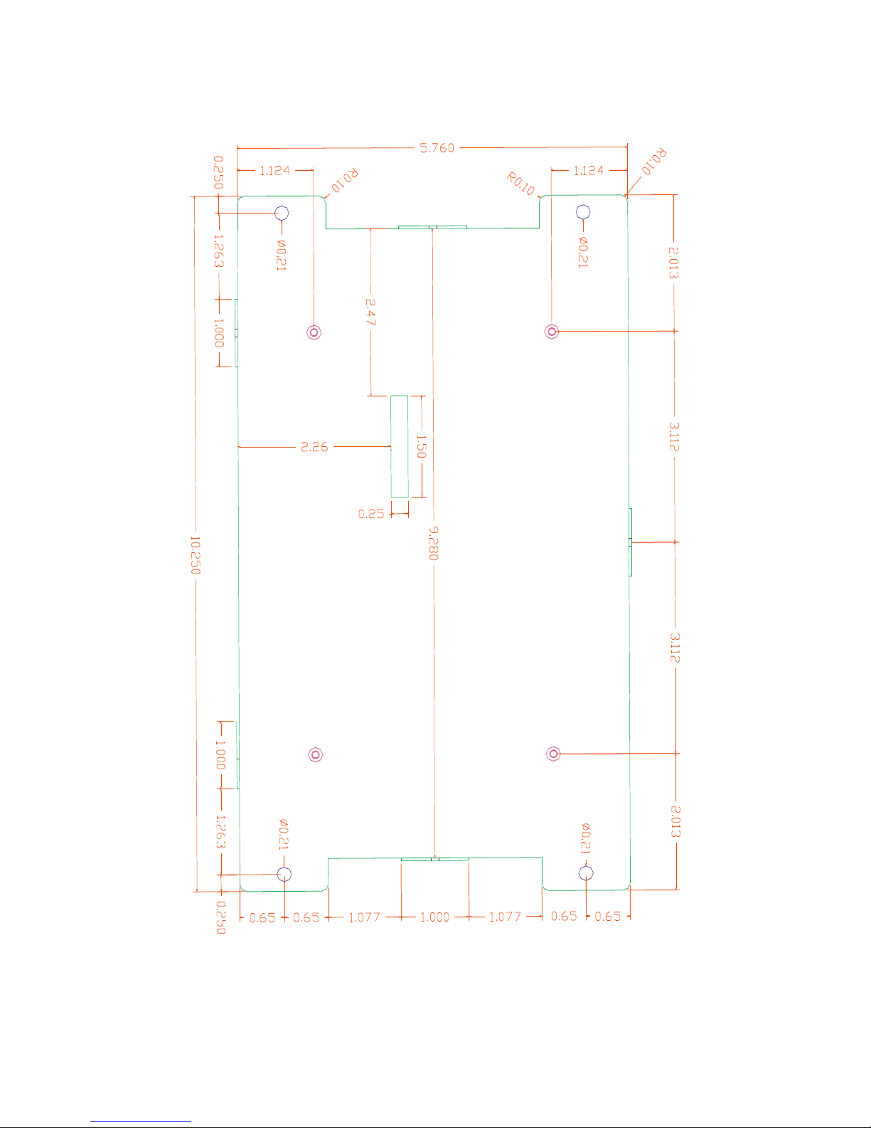
Appendix C: Mechanical drawing of Mounting Plate with dimensions
 Loading...