

Page 1
QSG_PPC-4510-KIT_1-00 page 1
HIO i.MX6 10.1” PC Quick Setup Guide
PPC-4510
Package Include:
1 x HIO-EMB-1200 Core Board
1 x HIO-PIO-1200 Carrier Board
1 x 10.1” Touch Panel (1280 x 720 px)
1 x WiFi Module and Antenna
1 x 12V Adapter
Safety Warning
The use and installation of this system should only be performed by
professionals. Improper installation of any electronic device or electrical
component can result in serious injury or death. Please make sure that all
safety precautions are taken into account.
Static-Sensitive Devices
Electrostatic-Discharge (ESD) can damage electronic components. To avoid
damaging your system board, it is important to handle it very carefully. The
following measures are generally sufficient to protect your equipment from
ESD.
Precautions
Use a grounded wrist strap designed to prevent static discharge.
Touch a grounded metal object before removing the board from the
antistatic bag.
Handle the board by its edges only; do not touch its components,
peripheral chips, memory modules or gold contacts.
When handling chips or modules, avoid touching their pins.
Put the motherboard and peripherals back into their antistatic bags
when not in use.
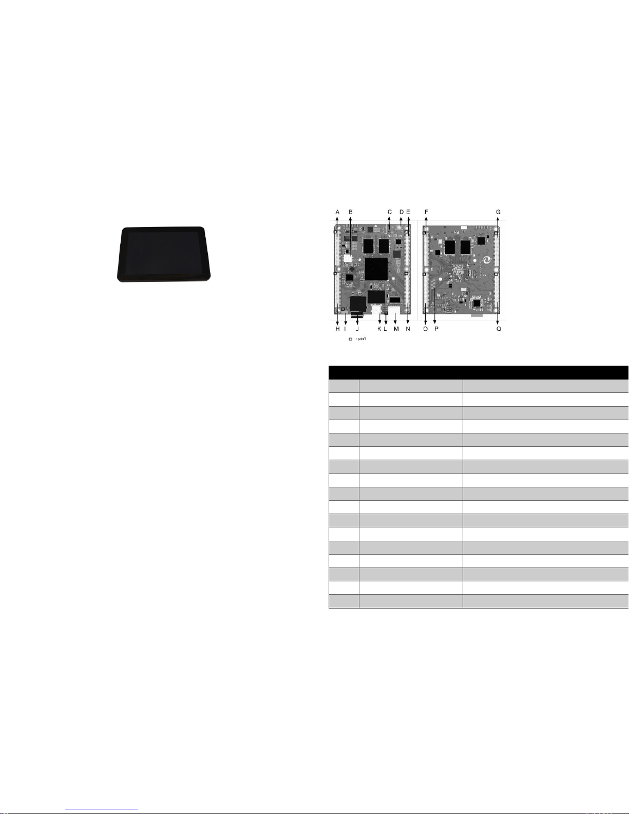
HIO-EMB-1200 Core Board Layout
Figure 2: HIO-EMB-1200 Core Board
Item
Connector
Description
A
J606 (top of J600)
Power, RTC and 24bit parallel display port
B
DIP Switch
2-bit DIP switch for boot selection TF/iNAND
C
DC Jack
5V DC Jack
D
Power Button
E
J608 (Top of J602)
LVDS, UARTs, CAN, I2C, GPIOs, VDD, VCC
F
J602 (Bottom of J608)
LVDS, UARTs, CAN, I2C, GPIOs, VDD, VCC
G
J600 (Bottom of 606)
Power and 24bit parellel display port
H
J607 (Top of J601)
Audio, USB, SDIO, Ethernet, I2C and SPI
I
Console UART
TTL serial port
J
SD Card Socket
Micro SD socket
K
OTG
OTG Device only
L
USB
2x USB 2.0 headers
M
Mini HDMI
HDMI with audio
N
J609 (top of J603)
GPIO, I2C, PCIe PH, MIPI DSI, CSI, Camera
O
J603 (Bottom of J609)
GPIO, I2C, PCIe PH, MIPI DSI, CSI, Camera
P
JTAG Q
J601 (Bottom of J607)
Audio, USB, SDIO, Ethernet, I2C, and SPI
Page 2
QSG_PPC-4510-KIT_1-00 page 2
Boot Up:
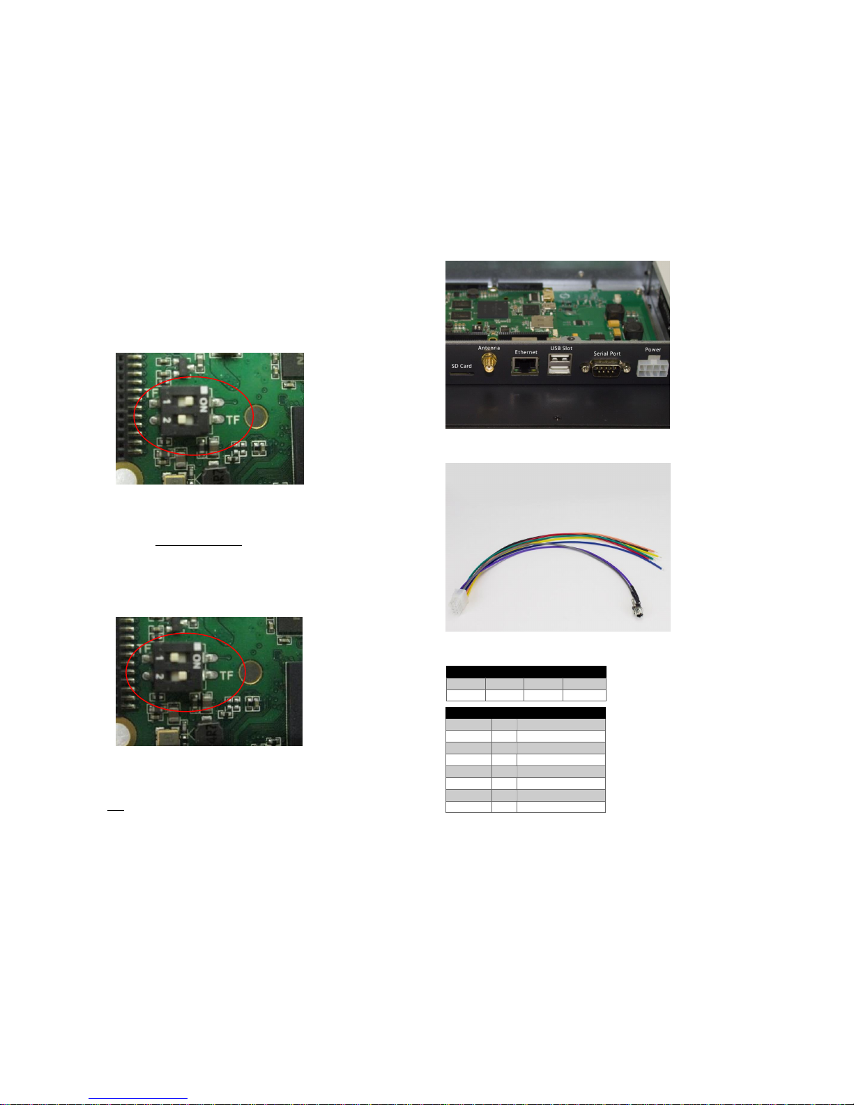
Boot Selection from the HIO-EMB-1200 Board
On the HIO Board, there is a switch with 2 selections, “1”(Default) and
“2”
#1 (Default) : To boot from the iNAND (Default OS Yocto Qt FB )
#2 : To boot from the TF (SD Card)
To build HIO-Yocto Image, Please visit
wiki.hioproject.org
The machine variable for the HIO i.MX6 10.1” Panel
PC is hio-imx6dl-ppc4510
Plug Yocto Build Micro SD Card into the SD Card Slot
Switch to number 2 on
Insert Molex Connector into the power Adapter and plug into the Power
slot
Machine will boot up and prompt to Enter Login Name
Enter “root” for Login Name
Figure 3: Side View
Figure 4: Molex Connector
Molex Connector Pin Layout
8 7 6 5 4 3 2
1
Wire
Pin
Function
Yellow
1
GND
Orange
2
TX
Blue 3 Reserved
Gray 4 VCC (24V)
Red 5 SHIELD
Black 6 RX
Green
7
Reserved
Purple
8
GND
 Loading...