

Page 1

PCM-9373
VIA Eden SBC with CPU, LCD,
LVDS, Ethernet and Audio
User’s Manual
Page 2

PCM-9373 User’s Manual ii
Copyright
This document is copyrighted, © 2003. All rights are reserved. The original manufacturer reserves the right to make improvements to the products described in this manual at any time without notice.
No part of this manual may be reproduced, copied, translated or transmitted in any form or by any means without the prior written permission of
the original manufacturer. Information provided in this manual is
intended to be accurate and reliable. However, the original manufacturer
assumes no responsibility for its use, nor for any infringements upon the
rights of third parties that may result from such use.
Acknowledgements
Award is a trademark of Award Software International, Inc.
VIA is a trademark of VIA Technologies, Inc.
IBM, PC/AT, PS/2 and VGA are trademarks of International Business
Machines Corporation.
Intel, Pentium, Celeron, and MMX are registered trademarks of Intel Corporation.
Microsoft Windows® is a registered trademark of Microsoft Corp.
RTL is a trademark of Realtek Semi-Conductor Co., Ltd.
ESS is a trademark of ESS Technology, Inc.
UMC is a trademark of United Microelectronics Corporation.
SMI is a trademark of Silicon Motion, Inc.
Creative is a trademark of Creative Technology LTD.
All other product names or trademarks are properties of their respective
owners.
For more information on this and other EMAC products, please visit
our websites at: http://www.emacinc.com
For technical support and service, please visit our support website at:
http://www.emacinc.com/support/
This manual is for the PCM-9373.
Part No. 2006937310 1st Edition
Printed in Taiwan August 2003
Page 3
iii
Packing List
Before you begin installing your card, please make sure that the following
materials have been shipped:
• 1 PCM-9373 all-in-one single board computer
• 1 startup manual
• CD-ROM or disks for utility, drivers, and manual (in PDF format)
• 1 3.5" IDE flat cable 40-pin to 40-pin (part no: 1701440351)
• 1 keyboard/ PS2 monse cable (part no. 1700060202)
• 1 second serial port cable (part no.1701140201)
• 1 parallel port cable (part no. 1700260250)
• 1 Audio cable (part no. 1703100152)
• 1 USB cable (part no. 1703100121)
If any of these items are missing or damaged, contact your distributor or
sales representative immediately.
Model No. List Description
PCM-9373F-J0A1 W/ Eden-400 CPU and heat sink
PCM-9373F-M0A1 W/ Eden-667 CPU and heat sink
PCM-9373F-S0A1 W/ C3-1GHz CPU and heat sink W/ FAN
Caution!
Achtung!
Possible danger of explosion if batteries (if any)
are incorrectly replaced.
Replace only with the same or equivalent type
recommended by the manufacturer.
Dispose of used batteries (if any) according to
the manufacturer's instructions.
Page 4

PCM-9373 User’s Manual iv
Additional Information and Assistance
1.Visit the EMAC, Inc. web site at www.emacinc.com where you can
find the latest information about the product.
2.Contact your distributor, sales representative, or EMAC, Inc customer
service for technical support if you need additional assistance.
Please have the following information ready before you call:
•Product name, serial number and invoice
•Description of your peripheral attachments
•Description of your software (operating system, version, application
software, etc.)
•A complete description of the problem
•The exact wording of any error messages
Page 5

v Table of Contents
Contents
Chapter 1 Introduction ......................................................2
1.1 Introduction ....................................................................... 2
1.1.1 Highly integrated multimedia SBC................................. 2
1.2 Features ............................................................................. 3
1.3 Specifications .................................................................... 3
1.3.1 Standard 3.5" Biscuit SBC Functions ............................. 3
1.3.2 VGA/LCD Interface ....................................................... 4
1.3.3 Ethernet Interface............................................................ 4
1.3.4 Audio Function ............................................................... 4
1.3.5 Mechanical and Environmental ...................................... 4
1.4 Board layout: dimensions.................................................. 5
Chapter 2 Installation ........................................................8
2.1 Jumpers.............................................................................. 8
Table 2.1:Jumpers ........................................................... 8
2.2 Connectors......................................................................... 8
Table 2.2:Connectors...................................................... 8
2.3 Locating jumpers............................................................. 10
Figure 2.1:Jumper locations.......................................... 10
2.4 Locating Connectors ........................... 11
Figure 2.2:Connectors (component side)...................... 11
Figure 2.3:Connectors (solder side).............................. 12
2.5 Setting Jumpers ............................................................... 13
2.6 Clear CMOS (S2)............................................................ 14
Table 2.3:CMOS clear (S2) .......................................... 14
2.7 Installing DIMMs............................................................ 15
2.8 IDE, CDROM hard drive connector (CN11) .................. 15
2.8.1 Connecting the hard drive............................................. 15
2.9 Solid State Disk............................................................... 16
2.9.1 CompactFlash (CN22) .................................................. 16
2.10 Optional floppy drive connector (CN23) ........................ 16
2.10.1 Connecting the floppy drive ......................................... 16
2.11 Parallel port connector (CN15) ....................................... 17
2.12 Keyboard and PS/2 mouse connector (CN18) ................ 17
2.13 Power & HDD LED, Reset Button Connector
(CN16, S3) ...................................................................... 17
2.13.1 Power & HDD LED (CN16) ........................................ 17
2.13.2 Reset switch (S3) .......................................................... 18
2.14 Power connectors (CN9, CN7, CN2).............................. 18
2.14.1 Peripheral power connector, -5 V, -12 V (CN9)......... 18
2.14.2 Main power connector, +5 V, +12 V (CN7)................ 18
Page 6

PCM-9373 User’s Manual vi
2.14.3 CPU Fan power supply connector (CN2)..................... 18
2.15 ATX power control connector (CN1, CN8).................... 18
2.15.1 ATX feature connector (CN1) and soft power switch
connector (CN8) ........................................................... 18
Figure 2.4:Wiring for ATX soft power switch function19
2.16 Audio interfaces (CN14) ................................................. 19
2.16.1 Audio connector (CN14) .............................................. 19
2.17 COM port connector (CN20,CN12)................................ 20
2.17.1 COM2 RS-232/422/485 setting (pin 1-6 of JP1).......... 20
Table 2.4: JP1: COM2 RS-232/422/485 select............. 20
2.18 VGA/LCD/LVDS interface connections ........................ 20
2.18.1 CRT display connector (CN21) .................................... 20
2.18.2 Flat panel display connector (CN4).............................. 20
2.18.3 Extension flat panel connector (CN3) .......................... 21
2.18.4 LVDS LCD panel connector (CN6) ............................. 21
2.18.5 Panel type selection (S1)............................................... 21
Table 2.5:S3 Panel Type select.................................... 21
2.19 TV-out interface (optional) (CN4, CN3)......................... 22
2.20 Ethernet configuration..................................................... 22
2.20.1 100Base-T connector (CN17)....................................... 22
2.20.2 Network boot ................................................................ 22
2.21 Watchdog timer configuration ........................................ 23
2.21.1 Watchdog timer action (pin 7-10 of JP1)...................... 23
Table 2.6:JP1 Watchdog timer action.......................... 23
2.22 USB connectors (CN19).................................................. 23
Chapter 3 Software Configuration .................................26
3.1 Introduction ..................................................................... 26
3.2 Connections to Three Standard LCDs............................. 26
3.2.1 Connections to Toshiba LTM10C209A
(640 x 480 TFT color LCD) ......................................... 26
Table 3.1:Connections to Toshiba LTM10C209A ....... 26
3.2.2 Connections to Toshiba LTM15C151A
(1024 x 768 TFT color LCD) ....................................... 27
Table 3.2:Connections to Toshiba ................................ 27
3.2.3 Connections to Toshiba LTM12C275A
(800 x 600 TFT color LCD) ......................................... 28
Table 3.3:Connections to Toshiba LTM12C275A ....... 28
3.3 Ethernet software configuration...................................... 29
Chapter 4 Award BIOS Setup.........................................32
4.1 System test and initialization........................................... 32
4.1.1 System configuration verification................................. 32
4.2 Award BIOS setup .......................................................... 33
4.2.1 Entering setup .............................................................. 33
Page 7

vii Table of Contents
Figure 4.1:BIOS setup program initial screen .............. 33
4.2.2 Standard CMOS Features setup .................................... 34
Figure 4.2:CMOS Features setup.................................. 34
4.2.3 Advanced BIOS Features setup .................................... 35
Figure 4.3:Advanced BIOS Features setup................... 35
4.2.4 Advanced Chipset Features setup ................................. 36
Figure 4.4:Advanced Chipset Features setup ............... 36
4.2.5 Integrated Peripherals ................................................... 37
Figure 4.5:Integrated Peripherals.................................. 37
4.2.6 Power Management Setup ............................................ 37
Figure 4.6:Power Management Setup........................... 37
4.2.7 PnP/PCI Configurations................................................ 38
Figure 4.7:PnP/PCI Configurations .............................. 38
4.2.8 PC Health Status ........................................................... 38
Figure 4.8:PC Health Status.......................................... 38
4.2.9 Frequency/Voltage Control........................................... 39
Figure 4.9:Frequency/Voltage Control ......................... 39
4.2.10 Load Optimized Defaults .............................................. 40
Figure 4.10:Load BIOS defaults screen........................ 40
4.2.11 Set Password ................................................................. 40
4.2.12 Save & Exit Setup......................................................... 41
4.2.13 Exit Without Saving...................................................... 42
Chapter 5 PCI SVGA Setup ............................................44
5.1 Introduction ..................................................................... 44
5.1.1 Chipset .......................................................................... 44
5.1.2 Display memory............................................................ 44
5.1.3 Display types................................................................. 44
5.1.4 Dual/Simultaneous Display .......................................... 44
Figure 5.1:Selecting Display Settings........................... 45
5.2 Installation of the SVGA Driver ..................................... 46
5.2.1 Installation for Windows 95 ......................................... 46
5.2.2 Installation for Windows 98/Me................................... 50
5.2.3 Installation for Windows NT ........................................ 55
5.2.4 Installation for Windows 2000 ..................................... 60
5.2.5 Installation for Windows XP ........................................ 65
5.3 Further Information......................................................... 71
Chapter 6 Audio Setup.....................................................74
6.1 Introduction ..................................................................... 74
6.2 DOS utilities.................................................................... 74
6.2.1 VIA Sound Blaster Pro compatible set up program ..... 74
6.2.2 VIA Sound Blaster Installation ..................................... 74
6.3 Driver installation............................................................ 75
6.3.1 Before you begin........................................................... 75
6.3.2 Windows 95/98 drivers................................................. 76
Page 8

PCM-9373 User’s Manual viii
6.3.3 Windows NT drivers..................................................... 83
6.3.4 Windows 2000 Drivers ................................................. 86
Chapter 7 PCI Bus Ethernet Interface...........................92
7.1 Introduction ..................................................................... 92
7.2 Installation of Ethernet driver ......................................... 92
7.2.1 Installation for MS-DOS and Windows 3.1.................. 92
7.2.2 Installation for Windows 98 ......................................... 93
7.2.3 Installation for Windows 2000 ..................................... 96
7.2.4 Installation for Windows NT ...................................... 101
7.3 Further information ....................................................... 107
Appendix A Programming the Watchdog Timer ..........110
A.1 Supported Input Timing Modes .................................... 110
Appendix B Installing PC/104 Modules .........................114
B.1 Installing PC/104 Modules............................................ 114
Figure B.1:PC/104 module mounting diagram........... 115
Figure B.2:PC/104 module dimensions (mm) (±0.1) . 116
Table B.1:PC/104 connectors (CN10)........................ 116
Appendix C Pin Assignments ..........................................120
C.1 CPU Fan Power Connector (CN2)................................ 120
Table C.1:IR connector (FAN 1) ................................ 120
C.2 Ethernet 10/100Base-T Connector (CN17)................... 120
Table C.2:Ethernet 10/100Base-T connector (CN17) 120
C.3 Audio Connector (CN14) .............................................. 121
Table C.3:Audio connector (CN14)............................ 121
C.4 Main Power Connector (CN7) ...................................... 121
Table C.4:Main Power Connector (CN7)................... 121
C.5 Keyboard and PS/2 Mouse Connector (CN18) ............. 122
Table C.5:Keyboard and mouse connector (CN18).... 122
C.6 Floppy Disk Drive Connector (CN23) .......................... 122
Table C.6:Floppy Disk Drive Connector (CN23)....... 122
C.7 IDE Hard Drive Connector (CN11) .............................. 123
Table C.7:IDE HDD connector (CN11) ..................... 123
C.8 Parallel Port Connector (CN15) ................. 124
Table C.8:Parallel Port Connector (CN15)................. 124
C.9 Power & HDD LED Connector (CN16) ................. 125
Table C.9:Power & HDD LED Connector (CN16).... 125
C.10 USB Connector (CN19) ........................................ 125
Table C.10:USB Connector (CN19)........................... 125
C.11 LCD Inverter Backlight Connector (CN5) .......... 126
Table C.11:LCD Inverter Backlight Connector
(CN5) ...................................................... 126
C.12 CRT Display Connector (CN21) ............................ 126
Page 9

ix Table of Contents
Table C.12:CRT Display Connector (CN21) ............. 126
C.13 Flat Panel Connector (CN4).......................................... 127
Table C.13:Flat Panel Connector (CN4)..................... 127
C.14 Extended Flat Panel Display Connector (CN3) ......... 128
Table C.14:Extended Flat Panel Display Connector
(CN3) ...................................................... 128
C.15 LCD Signal Mapping .................................................. 129
Table C.15:LCD Signal Mapping ............................... 129
C.16 LVDS Connector (CN6) ............................................ 130
Table C.16:LVDS Connector (CN6) .......................... 130
C.17 Peripheral Power Connector (CN9) .......................... 131
Table C.17:Peripheral Power Connector (CN9)......... 131
C.18 COM1 RS-232 serial port (CN20) ........................... 132
Table C.18:COM1 RS-232 serial port (CN20)........... 132
C.19 COM2 RS232/422/485 series port (CN12) .................. 132
Table C.19:COM2 RS-232/422/485 series port ......... 132
C.20 CompactFlash Card Connector (CN22) ...................... 133
Table C.20:CompactFlash Card Connector (CN22)... 133
C.21 ATX Power Feature Connector (CN1) ..................... 134
Table C.21:ATX Power Feature Connector (CN1) .... 134
C.22 IR connetor (CN13).......................... 134
Table C.22:IR Connector (CN26)............................... 134
Appendix D System Assignments....................................136
D.1 System I/O Ports............................................................ 136
Table D.1:System I/O ports ........................................ 136
D.2 1st MB memory map..................................................... 137
Table D.2:1st MB memory map ................................. 137
D.3 DMA channel assignments............................................ 137
Table D.3:DMA channel assignments........................ 137
D.4 Interrupt assignments .................................................... 138
Table D.4:Interrupt assignments ................................. 138
Appendix E Optional Extras for the PCM-9373 ............140
E.1 Optional LCD cables 10.4" TFT LCD panel (CN14) ... 140
Table E.1:Optional LCD cables 10.4" TFT LCD
panel ........................................................ 140
E.2 Optional USB cable (CN19) ......................................... 140
E.3 ATX Power Control Cable (CN1)................................. 140
E.4 Optional 24 bit LCD cable adaptor ............................... 140
E.5 +5V Fan for PCM-9373 heat sink ................................ 140
Appendix F Mechanical Drawings...................................142
Page 10

PCM-9373 User’s Manual x
F.1 Mechanical Drawings.................................................... 142
Figure F.1:PCM-9373 Mechanical Drawing
(Component Side) ................................... 142
Figure F.2:PCM-9373 Mechanical Drawing
(Solder Side) ........................................... 143
Page 11

CHAPTER
1
General Information
This chapter gives background information on the PCM-9373.
Sections include:
• Introduction
• Features
• Specifications
• Board layout and dimensions
Page 12

PCM-9373 User’s Manual 2
Chapter 1 Introduction
1.1 Introduction
The PCM-9373 is a VIA low-power Eden processor single board computer (SBC) with audio controller, a 4X AGP SVGA controller, a PCI 10/
100Base-T Ethernet interface, 2 Channel LVDS interface, and one PC/
104 expansion connector. The PCM-9373’s design is based on the 3.5"
HDD form factor that provides a convenient connector layout for easy
assembly, more efficient cable connections and better overall embedded
system integration. When using a VIA Eden processor, the PCM-9373
achieves outstanding performance that surpasses most SBCs in its class.
This compact (only 5.7" x 4") unit offers all the functions of a single
board industrial computer, but still fits in the space of a 3.5" floppy drive.
On-board features include, two serial ports (one RS-232, one RS-232/
422/485), one multi-mode parallel (ECP/EPP/SPP) port, two USB (Universal Serial Bus) ports, a floppy drive controller, and a keyboard/PS/2
mouse interface. The built-in high-speed PCI IDE controller supports
both PIO and UDMA/100 bus master modes. Up to four IDE devices can
be connected, including large hard disks, CD-ROM drives, and tape
backup drives.
The PCM-9373 features power management to minimize power consumption. It complies with the “Green Function” standard and supports
Doze, Standby and Suspend modes. In addition, the board‘s watchdog
timer can automatically reset the system or generate an interrupt if the
system stops due to a program bug or EMI.
1.1.1 Highly integrated multimedia SBC
The real estate is well-packed on this tightly designed 3.5" single board
computer (SBC) with an onboard new VIA Embedded low power Eden
or C3 EBGA processor. The VIA Eden processor uses advanced 0.15µ/
0.13µ CMOS technology with 128KB L1 cache memory and 64KB L2
cache memory on die. This board can operate without a fan at temperatures up to 60× C (140× F) and typically consumes under 12 Watts while
supporting numerous peripherals. This SBC includes a 4X AGP controller, an AC'97 audio interface, a PCI Ethernet interface, and 2 channel
LVDS interface. Its design is based on the 3.5" SBC form factor that supports the PC/104 interface for ISA module upgrades. Other on-board features include an LPT, 2 USBs, and 2 serial ports: 1 RS-232, and 1 RS232/422/485. The SSD solution supports CompactFlash™ cards Type I
and Type II.
Page 13

3 Chapter 1
1.2 Features
• Embedded VIA low-power Eden or C3 EBGA processor
• Supports one 36 bit TFT, 16-bit or 24-bit DSTN LCD panel, with up
to 1024 x 768 resolution
• Supports 2 channel LVDS interface
• 100/10Base-T Ethernet interface, IEEE 802.3U compatible
• Supports wake-on-Lan with ATX power supply
• 2 serial ports (one RS-232 and one RS-232/422/485)
• USB interface complies with USB Rev. 1.10
• 62-level Watchdog timer by system reset or IRQ
1.3 Specifications
1.3.1 Standard 3.5" Biscuit SBC Functions
• CPU:Onboard Eden 667 MHz (PCM-9373F M0A1) or VIA Eden 400
MHz (PCM-9373F-J0A1) or C3 - 1 GHz processor (PCM-9373FS0A1) with 128KB L1 cache memory)
• BIOS: Award 256 KB Flash memory
• System memory: One 144-pin SODIMM socket accepts 64 MB up to
512 MB SDRAM
• 2nd cache memory: 64 KB on the processor
• Enhanced IDE interface: One channels supports up to two EIDE
devices. BIOS auto-detect, PIO Mode 3 or Mode 4, supports up to
UDMA 33 mode
• Optional FDD interface: Supports up to two FDDs
• Serial ports: Two serial RS-232 ports, COM1: RS-232, COM2: RS232/422/485
• Parallel port: One parallel port, supports SPP/EPP/ECP mode
• Keyboard/mouse connector: Supports standard PC/AT keyboard and a
PS/2 mouse
• Power management: Supports power saving modes including Normal/
Standby/Suspend modes. APM 1.2 compliant
• Watchdog timer: 62 level timer intervals
Page 14

PCM-9373 User’s Manual 4
• USB: Two USB 1.1 compliant universal serial bus ports
• Expansion: One PC/104 connector for ISA control board
• Solid State Disk
Supports one 50-pin socket for CFC type I/II
1.3.2 VGA/LCD Interface
•
Chipset:
VIA Twister chip with integrated Savage4 2D/3D/Video Accelerator
•
Frame buffer:
Supports 4/8/16/32MB frame buffer with system memory
• Interface: 4X AGP VGA/LCD interface, Support for 9, 12, 15, 18, 24,
36 bit TFT and 16-bit or 24-bit DSTN panel
• Display mode: CRT Modes: 1280 x 1024@16bpp (60Hz), 1024 x
768@16bpp (85Hz); LCD/Simultaneous Modes: 1280 x
1024@16bpp (60Hz), 1024 x 768@16bpp (60Hz)
• LVDS: Supports 2 Channel (2 x 18bit) LVDS interface
1.3.3 Ethernet Interface
• Chipset: RTL 8100
• Ethernet interface: IEEE 802.3u 100BASE-T Fast Ethernet compatible
• I/O address switchless setting
• Built-in boot ROM
1.3.4 Audio Function
• Chipset: VIA 82C686
• Audio controller: AC'97 ver. 2.0 compliant interface
• Audio interface: Microphone in, line in, line out
1.3.5 Mechanical and Environmental
• Dimensions: 145 x 102 mm (5.9"x 4.2")
• Power supply voltage: +5 V
±5%
• Power requirements:
Max
4.99 A@+5 V (Within 5ms after power on)
Typica l
2.40 A@5 V (W/ Eden-400,128 MB)
2.75 A@5 V (W/ Eden-667,128 MB)
4.73 A@5V (W/ C3 1GHz, 128MB)
• Operating temperature: 0 ~ 60°C (32 ~ 140°F)
• Operating Humidity: 0% ~ 90% relative humidity, non-condensing
• Weight: 0.85 kg (weight of total package)
Page 15
5 Chapter 1
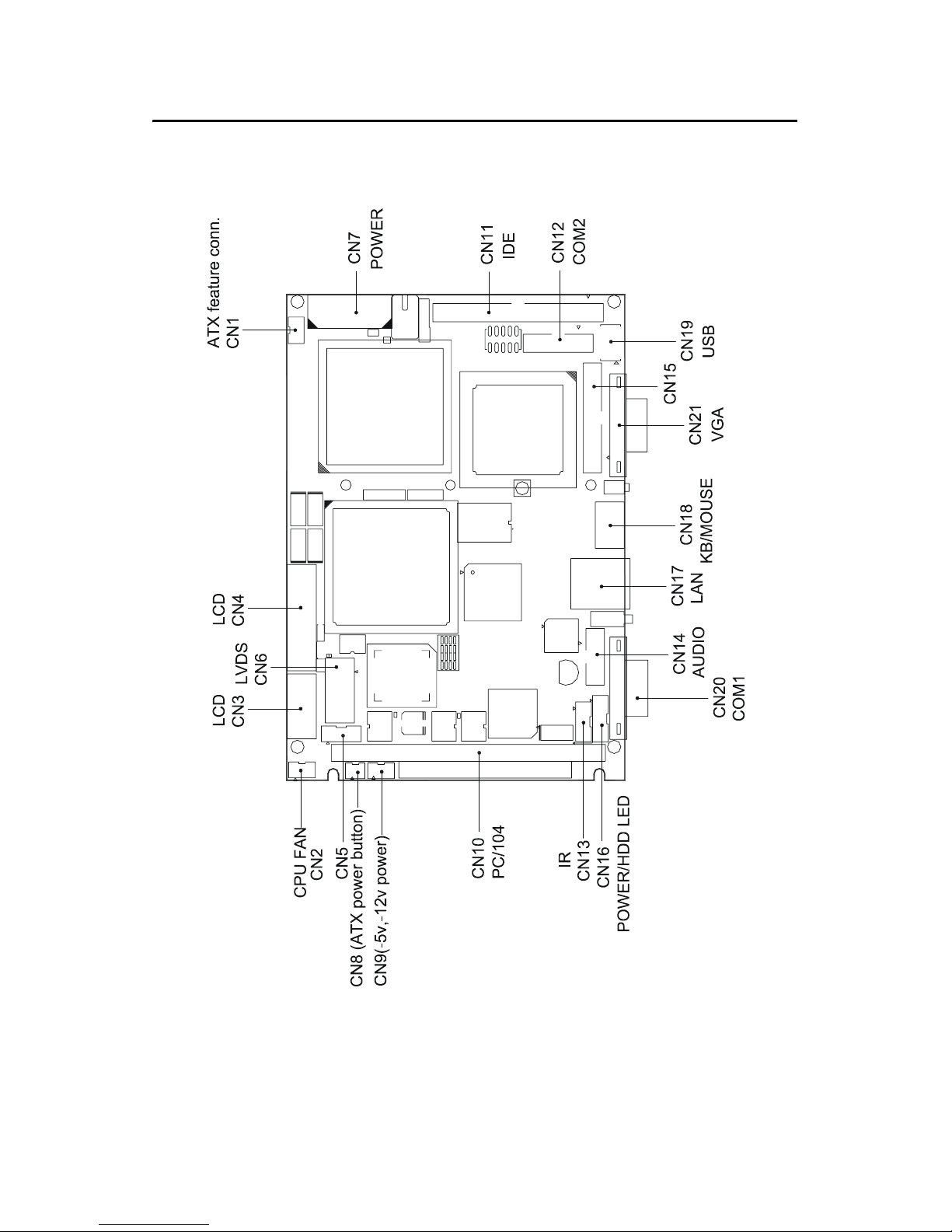
1.4 Board layout: dimensions
Figure 1.1: Board layout: dimensions
Page 16

PCM-9373 User’s Manual 6
Page 17

CHAPTER
2
Installation
This chapter explains the setup procedures of the PCM-9373 hardware,
including instructions on setting jumpers and connecting peripherals,
switches and indicators. Be sure to read
all safety precautions before you begin
the installation procedure.
Page 18

PCM-9373 User’s Manual 8
Chapter 2 Installation
2.1 Jumpers
The PCM-9373 has a number of jumpers that allow you to configure your
system to suit your application. The table below lists the functions of the
various jumpers.
2.2 Connectors
On-board connectors link the PCM-9373 to external devices such as hard
disk drives, a keyboard, or floppy drives. The table below lists the function of each of the board’s connectors.
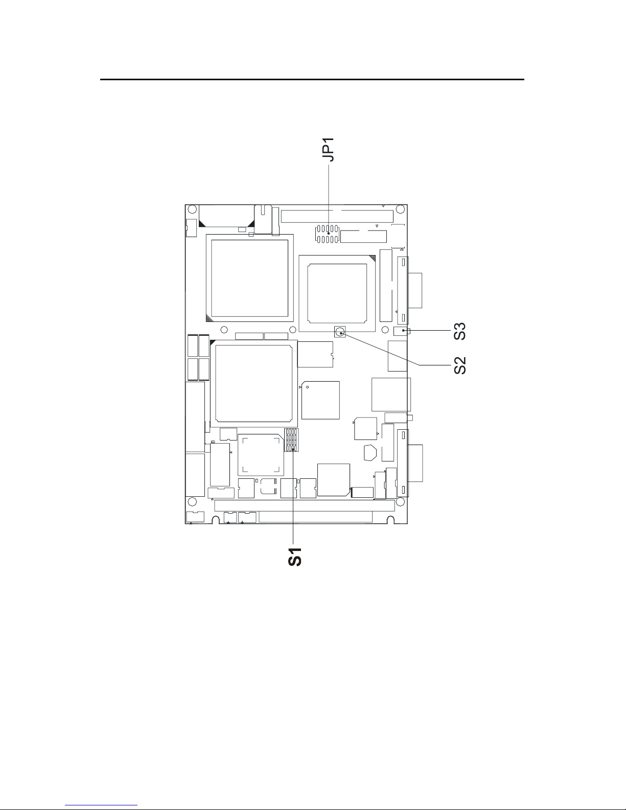
Table 2.1: Jumpers
Label Function
S1 Panel type select
S2 CMOS clear button
S3 System reset button
JP1 COM2 RS232/422/485 & WDT setting
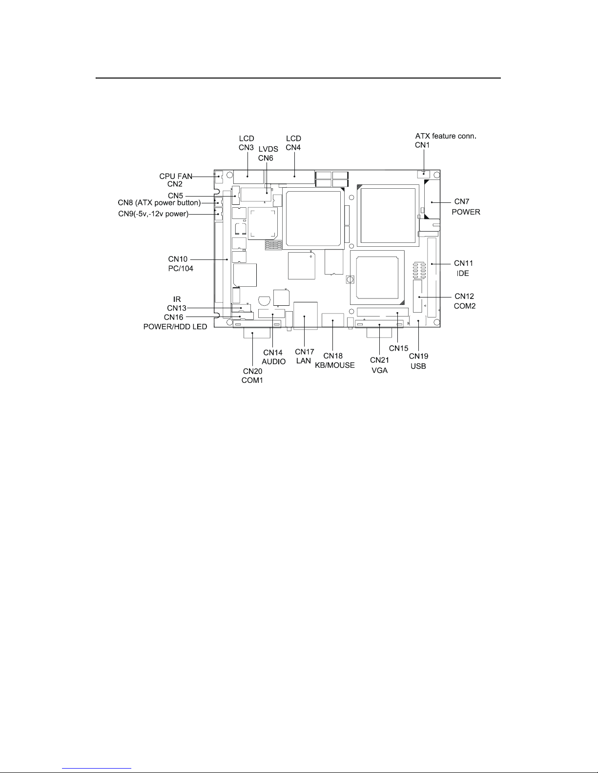
Table 2.2: Connectors
Label Function
CN1 ATX feature connector
CN2 CPU fan power connector
CN3 Ext. flat panel connector
CN4 Flat panel connector
CN5 LCD Inverter control connector
CN6 LVDS connector
CN7 Main Power connector
CN8 ATX power on/off switch connector
CN9 Peripheral power connector (-5V, -12V)
Page 19

9 Chapter 2
CN10 PC/104 expansion
CN11 IDE hard drive connector (primary)
CN12 COM2 port connector
CN13 IR connector
CN14 Audio connector
CN15 Parallel port connector
CN16 Power & HDD LED connector
CN17 Ethernet connector
CN18 Keyboard and PS/2 mouse connector
CN19 USB channel 1, 2 connector
CN20 COM 1 port connector
CN21 CRT display connector
CN22 CFC connector
CN23 Floppy drive connector (optional)
Table 2.2: Connectors
Page 20
PCM-9373 User’s Manual 10
2.3 Locating jumpers
Figure 2.1: Jumper locations
Page 21
11 Chapter 2
2.4 Locating Connectors
Figure 2.2: Connectors (component side)
Page 22
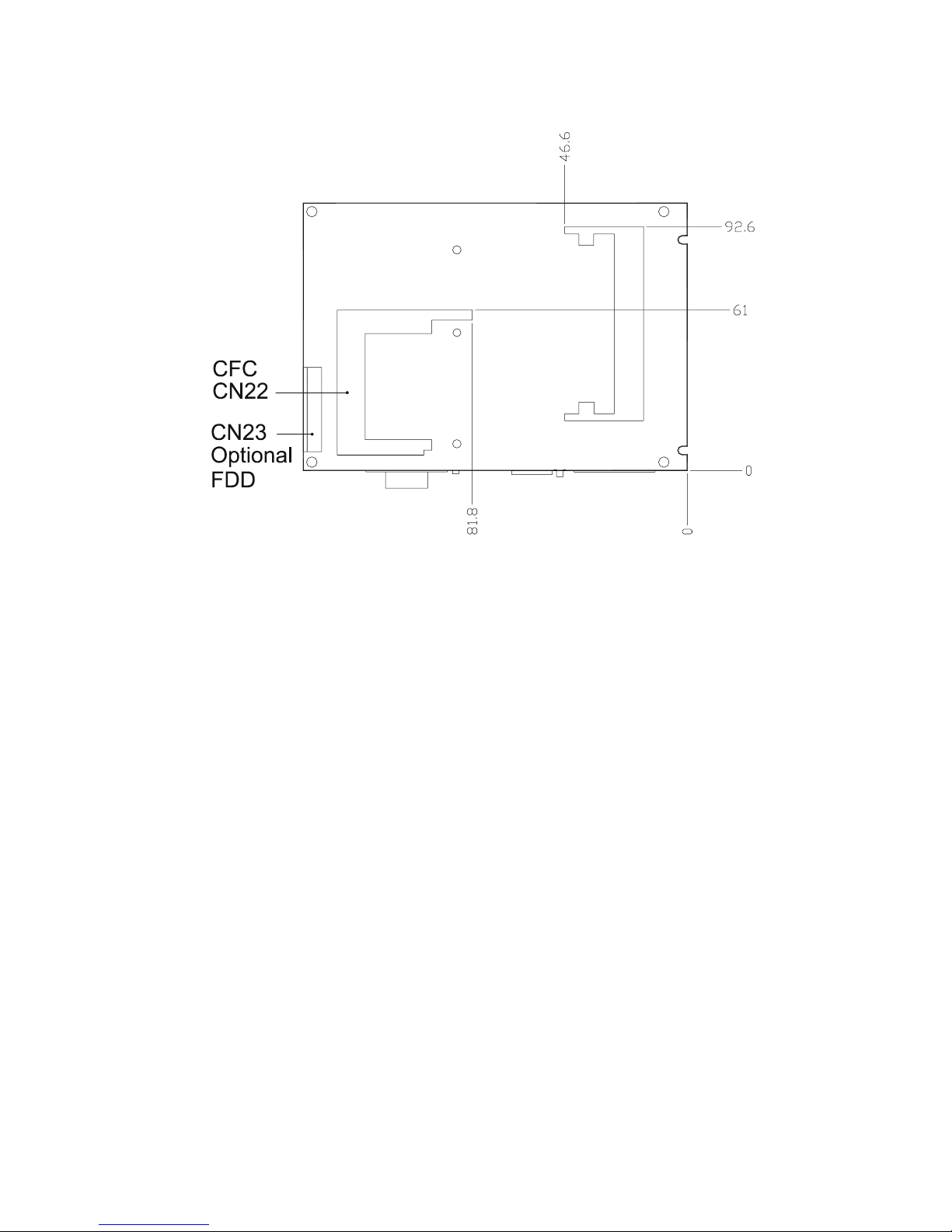
PCM-9373 User’s Manual 12
Figure 2.3: Connectors (solder side)
Page 23
13 Chapter 2
2.5 Setting Jumpers
You may configure your card to match the needs of your application by
setting jumpers. A jumper is a metal bridge used to close an electric circuit. It consists of two metal pins and a small metal clip (often protected
by a plastic cover) that slides over the pins to connect them. To “close” a
jumper, you connect the pins with the clip. To “open” a jumper, you
remove the clip. Sometimes a jumper will have three pins, labeled 1, 2
and 3. In this case you would connect either pins 1 and 2, or 2 and 3.
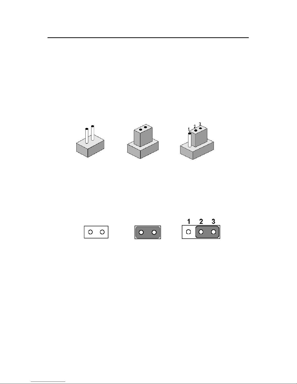
The jumper settings are schematically depicted in this manual as follows:.
A pair of needle-nose pliers may be helpful when working with jumpers.
If you have any doubts about the best hardware configuration for your
application, contact your local distributor or sales representative before
you make any changes.
Generally, you simply need a standard cable to make most connections.
open closed closed 2-3
open closed closed 2-3
Page 24

PCM-9373 User’s Manual 14
2.6 Clear CMOS (S2)
This jumper is used to erase CMOS data and reset system BIOS information.
The procedure for clearing CMOS is:
1. Turn off the system.
2. Short pin 2 and pin 3.
3. Return jumper to pins 1 and 2.
4. Turn on the system. The BIOS is now reset to its default setting
Warning!
To avoid damaging the computer, always turn
off the power supply before setting “Clear
CMOS.” Before turning on the power supply,
set the jumper back to “3.0 V Battery On.”
Table 2.3: CMOS clear (S2)
Condition Result
unpressed*
Normal
pushed Clear CMOS
* default setting
Page 25

15 Chapter 2
2.7 Installing DIMMs
The procedure for installing DIMMs is described below. Please follow
these steps carefully. The number of pins are different on either side of
the breaks, so the module can only fit in one way. DIMM modules have
different pin contacts on each side, and therefore have a higher pin density.
1. Make sure that the two handles of the DIMM socket are in the
“open” position. i.e. The handles remain leaning outward.
2. Slowly slide the DIMM module along the plastic guides on both
ends of the socket.
3. Press the DIMM module right down into the socket, until you hear
a click. This is when the two handles have automatically locked the
memory module into the correct position of the socket.
To remove the memory module, just push both handles outward, and the
module will be ejected from the socket.
2.8 IDE, CDROM hard drive connector (CN11)
The PCM-9373 provides 1 IDE channels which you can attach up to two
Enhanced Integrated Device Electronics hard disk drives or CDROM to
the PCM-9373’s internal controller. The PCM-9373's IDE controller uses
a PCI interface. This advanced IDE controller supports faster data transfer, PID mode 3, mode 4 and up to UDMA/33.
2.8.1 Connecting the hard drive
Connecting drives is done in a daisy-chain fashion. This package includes
1 44PIN IDE cable that can connect to 1.8" and 2.5" drives.
1. Connect one end of the cable to CN11. Make sure that the red (or
blue) wire corresponds to pin 1 on the connector, which is labeled
on the board (on the right side).
2. Plug the other end of the cable into the Enhanced IDE hard drive,
with pin 1 on the cable corresponding to pin 1 on the hard drive.
(See your hard drive’s documentation for the location of the con-
nector.)
Page 26

PCM-9373 User’s Manual 16
If desired, connect a second drive as described above.
Unlike floppy drives, IDE hard drives can connect to either end of the
cable. If you install two drives, you will need to set one as the master and
one as the slave by using jumpers on the drives. If you install only one
drive, set it as the master.
2.9 Solid State Disk
The PCM-9373 provides a CompactFlash™ card socket and DiskOnChip
socket for Solid state disk solutions.
2.9.1 CompactFlash (CN22)
The CompactFlash card shares a secondary IDE channel which can be
enabled/disabled via the BIOS settings.
2.10 Optional floppy drive connector (CN23)
You can attach up to two floppy drives to the PCM-9373’s on-board controller. You can use 3.5” (720 KB, 1.44 MB, and 2.88 MB) drives.
A 26-pin FPC connector cable is required for a dual-drive system. On one
end of the cable is a 26-pin FPC-cable connector. On the other end are
two sets of floppy disk drive connectors. Each set consists of a 26-pin
FPC-cable connector (usually used for 3.5” drives).
2.10.1 Connecting the floppy drive
1. Plug the 26-pin FPC-cable connector into CN23. Make sure that the
red wire corresponds to pin one on the connector.
2. Attach the appropriate connector on the other end of the cable to
the floppy drive(s). You can use only one connector in the set. The
set on the end (after the twist in the cable) connects to the A: drive.
The set in the middle connects to the B: drive.
If you are connecting a 3.5” floppy drive, you may have trouble determining which pin is number one. Look for a number printed on the circuit
board indicating pin number one. In addition, the connector on the floppy
drive may have a slot. When the slot is up, pin number one should be on
the right. Check the documentation that came with the drive for more
information.
If you desire, connect the B: drive to the connectors in the middle of the
cable as described above.
Page 27

17 Chapter 2
In case you need to make your own cable, you can find the pin assignments for the board’s connector in Appendix C.
2.11 Parallel port connector (CN15)
Normally, the parallel port is used to connect the card to a printer. The
PCM-9373 includes a multi-mode (ECP/EPP/SPP) parallel port accessed
via CN15 and a 26-pin flat-cable connector. You will need an adapter
cable if you use a traditional DB-25 connector. The adapter cable has a
26-pin connector on one end, and a DB-25 connector on the other.
The parallel port is designated as LPT1, and can be disabled or changed to
LPT2 or LPT3 in the system BIOS setup.
The parallel port interrupt channel is designated to be IRQ7.
You can select ECP/EPP DMA channel via BIOS setup.
2.12 Keyboard and PS/2 mouse connector (CN18)
The PCM-9373 board provides a keyboard connector that supports both a
keyboard and a PS/2 style mouse. In most cases, especially in embedded
applications, a keyboard is not used. If the keyboard is not present, the
standard PC/AT BIOS will report an error or fail during power-on selftest (POST) after a reset. The PCM-9373’s BIOS standard setup menu
allows you to select “All, But Keyboard” under the “Halt On” selection.
This allows no-keyboard operation in embedded system applications,
without the system halting under POST.
2.13 Power & HDD LED, Reset Button Connector
(CN16, S3)
Next, you may want to install external switches to monitor and control the
PCM-9373. These features are optional: install them only if you need
them. The Power & HDD LED connector (CN16) is 6-pin Wafer box
connector. It provides connections for a power and hard disk access indicator.
2.13.1 Power & HDD LED (CN16)
The HDD LED indicator for hard disk access is an active low signal (24
mA sink rate). Power supply activity LED indicator.
Page 28

PCM-9373 User’s Manual 18
2.13.2 Reset switch (S3)
If you install a reset switch, it should be an open single pole switch.
Momentarily pressing the switch will activate a reset. The switch should
be rated for 10 mA, 5 V.
2.14 Power connectors (CN9, CN7, CN2)
2.14.1 Peripheral power connector, -5 V, -12 V (CN9)
Supplies secondary power to devices that require -5 V and -12 V.
2.14.2 Main power connector, +5 V, +12 V (CN7)
Supplies main power to the PCM-9373 (+5 V), and to devices that require
+12 V.
2.14.3 CPU Fan power supply connector (CN2)
Provides +5V power supply to CPU cooling fan.
2.15 ATX power control connector (CN1, CN8)
2.15.1 ATX feature connector (CN1) and soft power
switch connector (CN8)
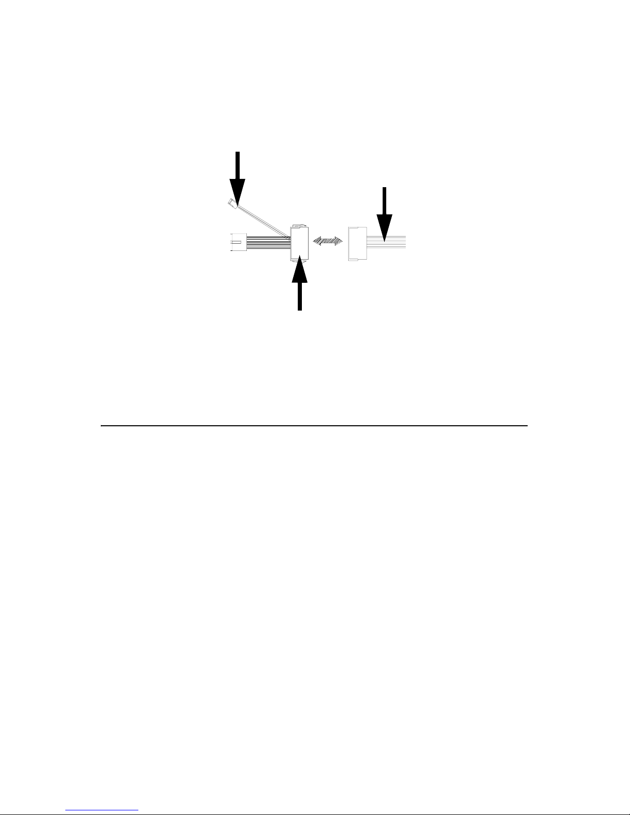
The PCM-9373 can support an advanced soft power switch function, if an
ATX power supply is used. To enable the soft power switch function:
1. Get the specially designed ATX-to-big 4P power cable
(PCM-9373 optional item, part no. 1703200100)
2. Connect the 3-pin plug of the cable to CN1 (ATX feature connec-
tor).
3. Connect the power on/off button to CN8. (A momentary type of
button should be used.)
Important
Make sure that the ATX power supply can take
at least a 10 mA load on the 5 V standby lead
(5VSB). If not, you may have difficulty powering on your system.
Page 29
19 Chapter 2
2.16 Audio interfaces (CN14)
The PCM-9373 is equipped with a high-quality audio interface, which
provides 16-bit CD-quality recording and playback as well as OPL3 compatible FM music. It is supported by all major operating systems.
2.16.1 Audio connector (CN14)
The PCM-9373 provides all major audio signals on a 10-pin flat-cable
connector, CN14. These audio signals include Microphone in (mono),
Line in (stereo) and Line out (stereo). If you use traditional telephone jack
connectors for these audio signals, you will need an adapter cable.
Figure 2.4: Wiring for ATX soft power switch function
to CN1 ATX
features connector
ATX
power supply
to main power
connector CN7
20-pin
female connector
Page 30

PCM-9373 User’s Manual 20
2.17 COM port connector (CN20,CN12)
The PCM-9373 provides two serial ports (COM1: RS-232; COM2: RS232/422/485) in one DB-9 connector (COM1) and one 14-pin dual-inline,
male header. It provides connections for serial devices (a mouse, etc.) or a
communication network. You can find the pin assignments for the COM
port connector in Appendix C.
2.17.1 COM2 RS-232/422/485 setting (pin 1-6 of JP1)
COM2 can be configured to operate in RS-232, RS-422, or RS-485 mode.
This is done via JP1
2.18 VGA/LCD/LVDS interface connections
The PCM-9373’s PCI SVGA interface can drive conventional CRT displays and is capable of driving a wide range of flat panel displays, including passive LCD and active LCD displays. The board has three
connectors to support these displays: one for standard CRT VGA monitors, one for flat panel displays, and one for LVDS type LCD panels.
2.18.1 CRT display connector (CN21)
CN21 is a 16-pin, dual-inline header used for conventional CRT displays.
A simple one-to-one adapter can be used to match CN21 to a standard 15pin D-SUB connector commonly used for VGA.
Pin assignments for CRT display connector CN21 are detailed in Appendix C.
2.18.2 Flat panel display connector (CN4)
CN4 consists of a 40-pin connector which can support a 24-bit LCD
panel. It is Hirose’s product no. DF13A-40DP-1.25 V
The PCM-9373 provides a bias control signal on CN11 that can be used
to control the LCD bias voltage. It is recommended that the LCD bias
voltage not be applied to the panel until the logic supply voltage (+5 V or
+3.3 V) and panel video signals are stable. Under normal operation, the
control signal (ENAVEE) is active high. When the PCM-9373’s power is
Table 2.4: JP1: COM2 RS-232/422/485 select
PINS RS-232* RS-422 RS-485
1-2 Open Open Closed
3-4 Open Closed Open
5-6 Closed Open Open
Page 31

21 Chapter 2
applied, the control signal is low until just after the relevant flat panel signals are present. CN4 can connect up to 24 bit TFT LCD.
2.18.3 Extension flat panel connector (CN3)
CN3 consists of a 20-pin connector which is Hirose’s product no.
DF13A-20DP-1.25V. The PCM-9373 supports a 36-bit LCD panel which
must be connected to both the CN4 (40-pin) and the CN3 (20-pin). The
pin assignments for both CN4 and the CN3 can be found in Appendix C
2.18.4 LVDS LCD panel connector (CN6)
The PCM-9373 uses the VIA Twister chip that supports 2 channel (2 x
18 bit) LVDS LCD panel displays. Users can connect to either an 18-bit
or 36-bit LVDS LCD with CN6.
2.18.5 Panel type selection (S1)
S1 is an 8 segment DIP switch for DSTN/TFT panel type and resolution
functions.
Table 2.5: S3 Panel Type select
SW SW SW SW
1-1 1-2 1-3 1-4 Panel type
ON ON ON ON DSTN** 640x480 18bit
ON ON ON OFF TFT 640x480 18bit
ON ON OFF ON TFT 640x480 LVDS
ON ON OFF OFF (Resvd)
ON OFF ON ON (Resvd)
ON OFF ON OFF DSTN** 800x600 18bit
ON OFF OFF ON TFT* 800x600 18bit
ON OFF OFF OFF TFT 800x600 LVDS
OFF ON ON ON (Resvd)
OFF ON ON OFF (Resvd)
OFF ON OFF ON DSTN** 1024x768 36bit
OFF ON OFF OFF TFT 1024x768 36bit
OFF OFF ON ON TFT 1024x768 1Chan LVDS
OFF OFF ON OFF TFT 1024x768 2Chan LVDS
OFF OFF OFF ON TFT 1024x768 18bit
OFF OFF OFF OFF TFT 1024x768 24bit
Page 32

PCM-9373 User’s Manual 22
2.19 TV-out interface (optional) (CN4, CN3)
The PCM-9373 board provides optional TV-out module PCM-232 via
CN4, CN3. This module output supports composite video and S-video
connectors. TV-out generators use both NTSC and PAL formats with 640
x 480 or 800 x 600 resolution.
To set up your video interface:
1. Run the appropriate installation program located on the utility disk.
That’s all there is to it.
2.20 Ethernet configuration
The PCM-9373 is equipped with a high performance 32-bit PCI-bus
Ethernet interface which is fully compliant with IEEE 802.3U 10/
100Mbps CSMA/CD standards. It is supported by all major network
operating systems.
The medium type can be configured via the RSET8139.EXE program
included on the utility disk. (See Chapter 3 for detailed information.)
2.20.1 100Base-T connector (CN17)
100Base-T connections are made via the on-board RJ-45 connector
2.20.2 Network boot
The Network Boot feature can be utilized by incorporating the Boot
ROM image files for the appropriate network operating system. The Boot
ROM BIOS files are included in the system BIOS, which is on the utility
CD disc.
* Default setting
** will support in the future
Table 2.5: S3 Panel Type select
Page 33

23 Chapter 2
2.21 Watchdog timer configuration
An on-board watchdog timer reduces the chance of disruptions which
EMP (electro-magnetic pulse) interference can cause. This is an invaluable protective device for standalone or unmanned applications. Setup
involves one jumper and running the control software (refer to Appendix
A).
2.21.1 Watchdog timer action (pin 7-10 of JP1)
When the watchdog timer activates (CPU processing has come to a halt),
it can reset the system or generate an interrupt on IRQ11. This can be set
via setting JP1 as shown below:
* Default setting
2.22 USB connectors (CN19)
The PCM-9373 board provides up to four USB (Universal Serial Bus)
ports. This gives complete Plug and Play, and hot attach/detach for up to
127 external devices. The USB interfaces comply with USB specification
Rev. 1.1, and are fuse protected.
The USB interface is accessed through two 5 x 2-pin flat-cable connectors, CN19 (USB1, 2). You will need an adapter cable if you use a standard USB connector. The adapter cable has a 5 x 2-pin connector on one
end and a USB connector on the other.
The USB interfaces can be disabled in the system BIOS setup.
Table 2.6: JP1 Watchdog timer action
Pins System reset* IRQ11
7-8 closed open
9-10 open closed
Page 34

PCM-9373 User’s Manual 24
Page 35

CHAPTER
3
Software Configuration
This chapter details the software configuration information. It shows you
how to configure the card to match
your application requirements. The
AWARD System BIOS is covered in
Chapter 4.
Sections include:
• Introduction
• Connections for standard LCDs
• Ethernet interface configuration.
Page 36

PCM-9373 User’s Manual 26
Chapter 3 Software Configuration
3.1 Introduction
The PCM-9373 system BIOS and custom drivers are located in a 256
Kbyte, Flash ROM device, designated U5. A single Flash chip holds the
system BIOS, VGA BIOS and network Boot ROM image. The display
can be configured via CMOS settings. This method minimizes the number of chips and difficulty of configuration. To set different types of LCD
panels, please choose “panel type” from the “integrated peripherals”
menu in CMOS setup.
3.2 Connections to Three Standard LCDs
The following tables illustrate typical LCD connection pinouts for the
PCM-9373.
3.2.1 Connections to Toshiba LTM10C209A (640 x 480 TFT
color LCD)
Table 3.1: Connections to Toshiba LTM10C209A
LTM10C209A PCM-9373 CN4
Pin Name Pin Name
1 GND 3 GND
2 CLK 35 SHFCLK
3GND 34GND
4R0 27P18
5R1 28P19
6R2 29P20
7GND 33GND
8R3 30P21
9R4 31P22
10 R5 32 P23
11 GND 34 GN D
12 G0 19 P10
13 G1 20 P11
14 G2 21 P12
15 GND 8 GND
Page 37

27 Chapter 3
3.2.2 Connections to Toshiba LTM15C151A (1024 x 768 TFT
color LCD)
16 G3 22 P13
17 G4 23 P14
18 G5 24 P15
19 GND 8 GND
20 ENAB 37 M/DE
21 GND 4 GND
22 B0 11 P2
23 B1 12 P3
24 B2 13 P4
25 GND 4 GND
26 B3 14 P5
27 B4 15 P6
28 B5 16 P7
29 GND 3 GND
30 VDD 1 +5 V
31 VDD 2 +5 V
Table 3.2: Connections to Toshiba
LTM15C151A
PCM-9373 CN2
Pin Name Pin Name
CN1-1 GND CN 4-33 GND
CN1-2 NCLK CN 4-35 LDSCLK1
CN1-3 NC
CN1-4 NC
CN1-5 GND CN 4-3 GND
CN1-6 OR0 CN 4-9 PD0
CN1-7 OR1 CN 4-11 PD2
CN1-8 OR2 CN 4-13 PD4
CN1-9 OR3 CN 4-15 PD6
CN1-10 OR4 CN 4-17 PD8
CN1-11 OR5 CN 4-19 PD10
CN1-12 GND CN 4-3 GND
Table 3.1: Connections to Toshiba LTM10C209A
Page 38

PCM-9373 User’s Manual 28
3.2.3 Connections to Toshiba LTM12C275A (800 x 600 TFT
color LCD)
CN1-13 OG0 CN 4-21 PD12
CN1-14 OG1 CN 4-23 PD14
CN1-15 OG2 CN 4-25 PD16
CN1-16 OG3 CN 4-27 PD18
CN1-17 OG4 CN 4-29 PD20
CN1-18 OG5 CN 4-31 PD22
CN1-19 GND CN 3-1 GND
CN1-20 OB0 CN 3-3 PD24
CN1-21 OB1 CN 3-5 PD26
CN1-22 OB2 CN 3-7 PD28
CN1-23 OB3 CN 3-9 PD30
CN1-24 OB4 CN 3-11 PD32
CN1-25 OB5 CN 3-13 PD34
CN1-26 ENAB CN 4-37 M/DE
CN1-27 GND CN 4-34 GND
CN1-28 VDD CN 4-1 +5V
CN1-29 VDD CN 4-2 +5V
CN1-30 GND CN 4-8 GND
Table 3.3: Connections to Toshiba LTM12C275A
LTM12C275A PCM-9373 CN4
Pin Name Pin Name
1 GND 3 GND
2 NCLK 35 SHFCLK
3NC -NC
4NC -NC
5 GND 4 GND
6R0 27P18
7R1 28P19
8R2 29P20
9R3 30P21
Table 3.2: Connections to Toshiba
Page 39

29 Chapter 3
3.3 Ethernet software configuration
The PCM-9373’s on-board Ethernet interface supports all major network
operating systems. To configure the medium type, to view the current
configuration, or to run diagnostics, do the following:
1. Power the PCM-9373 on. Make sure that the RSET8139.EXE file
is located in the working drive.
2. At the prompt, type RSET8139.EXE and press <Enter>. The Ether-
net configuration program will then be displayed.
3. This simple screen shows all the available options for the Ethernet
interface. Just highlight the option you wish to change by using the
Up and Down keys. To change a selected item, press <Enter>, and
a screen will appear with the available options. Highlight your
10 R4 31 P22
11 R5 32 P23
12 GND 8 GND
13 G0 19 P10
14 G1 20 P11
15 G2 21 P12
16 G3 22 P13
17 G4 23 P14
18 G5 24 P15
19 GND 33 GND
20 B0 11 P2
21 B1 12 P3
22 B2 13 P4
23 B3 14 P5
24 B4 15 P6
25 B5 16 P7
26 ENAB 37 M/DE
27 GND 34 GND
28 VCC 5 +5 V
29 VCC 6 +5 V
30 GND 39 GND
Table 3.3: Connections to Toshiba LTM12C275A
Page 40

PCM-9373 User’s Manual 30
option and press <Enter>. Each highlighted option has a helpful
message guide displayed at the bottom of the screen for additional
information.
4. After you have made your selections and are sure this is the config-
uration you want, press ESC. A prompt will appear asking if you
want to save the configuration. Press Y if you want to save.
The Ethernet Setup Menu also offers three very useful diagnostic functions. These are:
1. Run EEPROM Test.
2. Run Diagnostics on Board.
3. Run Diagnostics on Network.
Each option has its own display screen that shows the format and result of
any diagnostic tests undertaken.
Note For Ethernet installation, please see Chapter 7
Page 41

CHAPTER
4
Award BIOS Setup
This chapter describes how to set BIOS
configuration data.
Page 42

PCM-9373 User’s Manual 32
Chapter 4 Award BIOS Setup
4.1 System test and initialization
These routines test and initialize board hardware. If the routines encounter an error during the tests, you will either hear a few short beeps or see
an error message on the screen. There are two kinds of errors: fatal and
non-fatal. The system can usually continue the boot up sequence with
non-fatal errors. Non-fatal error messages usually appear on the screen
along with the following instructions:
press <F1> to RESUME
Write down the message and press the F1 key to continue the bootup
sequence.
4.1.1 System configuration verification
These routines check the current system configuration against the values
stored in the board’s CMOS memory. If they do not match, the program
outputs an error message. You will then need to run the BIOS setup program to set the configuration information in memory.
There are three situations in which you will need to change the CMOS
settings:
1. You are starting your system for the first time
2. You have changed the hardware attached to your system
3. The CMOS memory has lost power and the configuration informa-
tion has been erased.
The PCM-9373 Series' CMOS memory has an integral lithium battery
backup. The battery backup should last ten years in normal service, but
when it finally runs down, you will need to replace the complete unit.
Page 43
33 Chapter 4
4.2 Award BIOS setup
Award’s BIOS ROM has a built-in Setup program that allows users to
modify the basic system configuration. This type of information is stored
in battery-backed CMOS RAM so that it retains the Setup information
when the power is turned off.
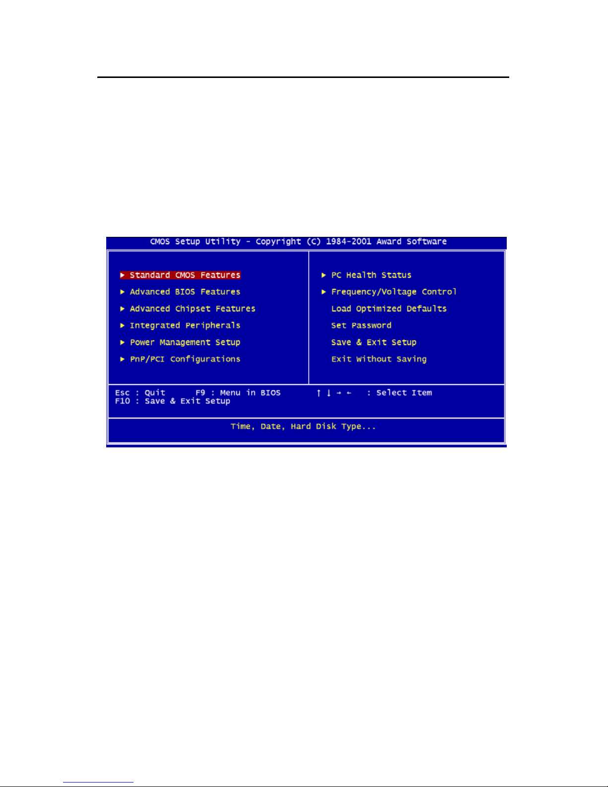
4.2.1 Entering setup
Power on the computer and press <Del> immediately. This will allow you
to enter Setup.
Figure 4.1: BIOS setup program initial screen
Page 44
PCM-9373 User’s Manual 34
4.2.2 Standard CMOS Features setup
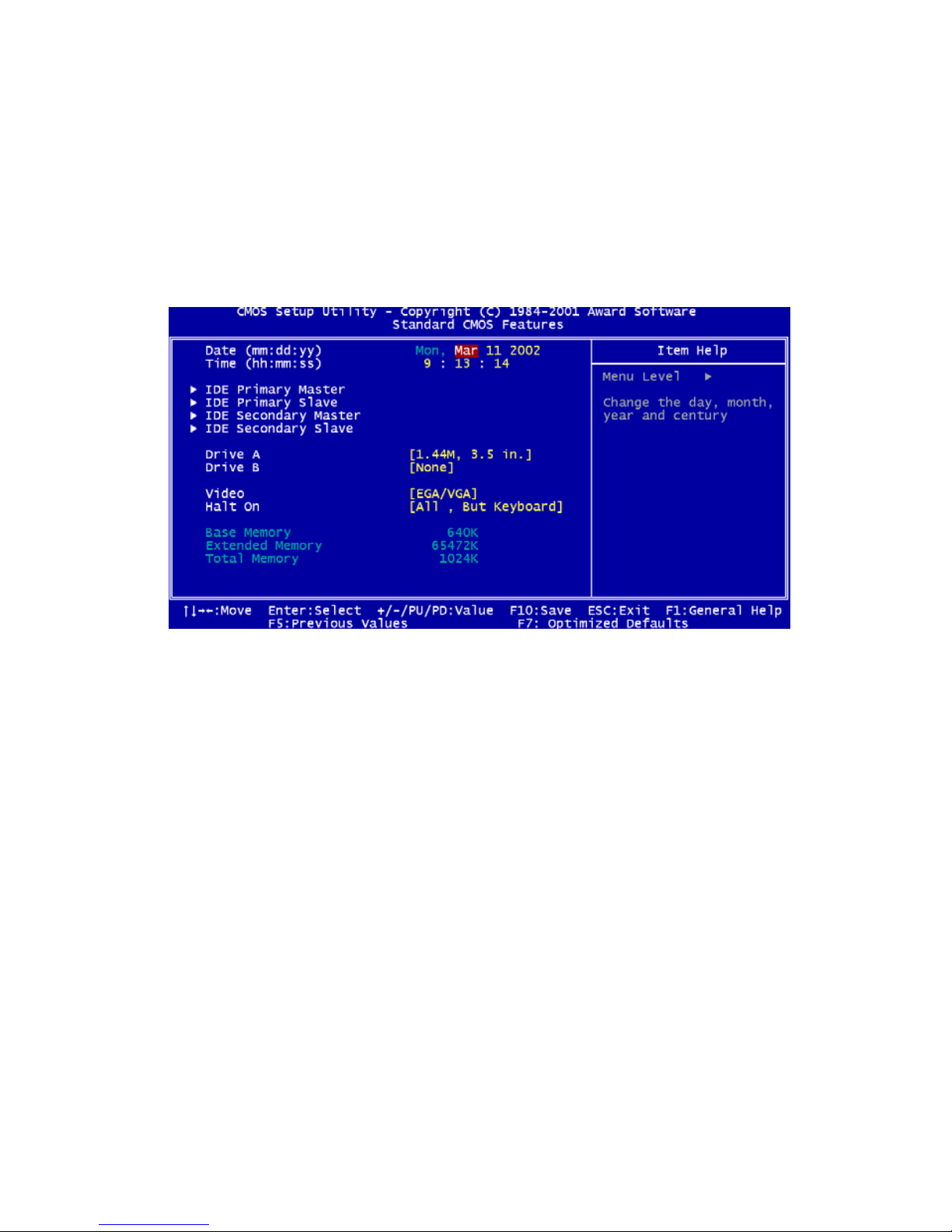
When you choose the Standard CMOS Features option from the Initial
Setup Screen menu, the screen shown below is displayed. This standard
Setup Menu allows users to configure system components such as date,
time, hard disk drive, floppy drive and display. Once a field is highlighted, on-line help information is displayed in the left bottom of the
Menu screen.
Figure 4.2: CMOS Features setup
Page 45
35 Chapter 4
4.2.3 Advanced BIOS Features setup
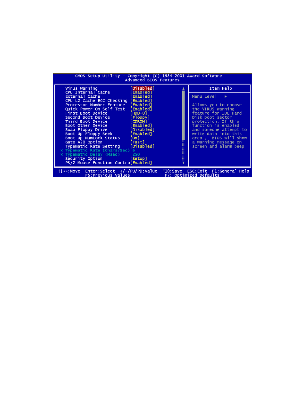
By choosing the Advanced BIOS Features Setup option from the Initial
Setup Screen menu, the screen below is displayed. This sample screen
contains the manufacturer’s default values for the PCM-9373 Series.
Figure 4.3: Advanced BIOS Features setup
Page 46
PCM-9373 User’s Manual 36
4.2.4 Advanced Chipset Features setup
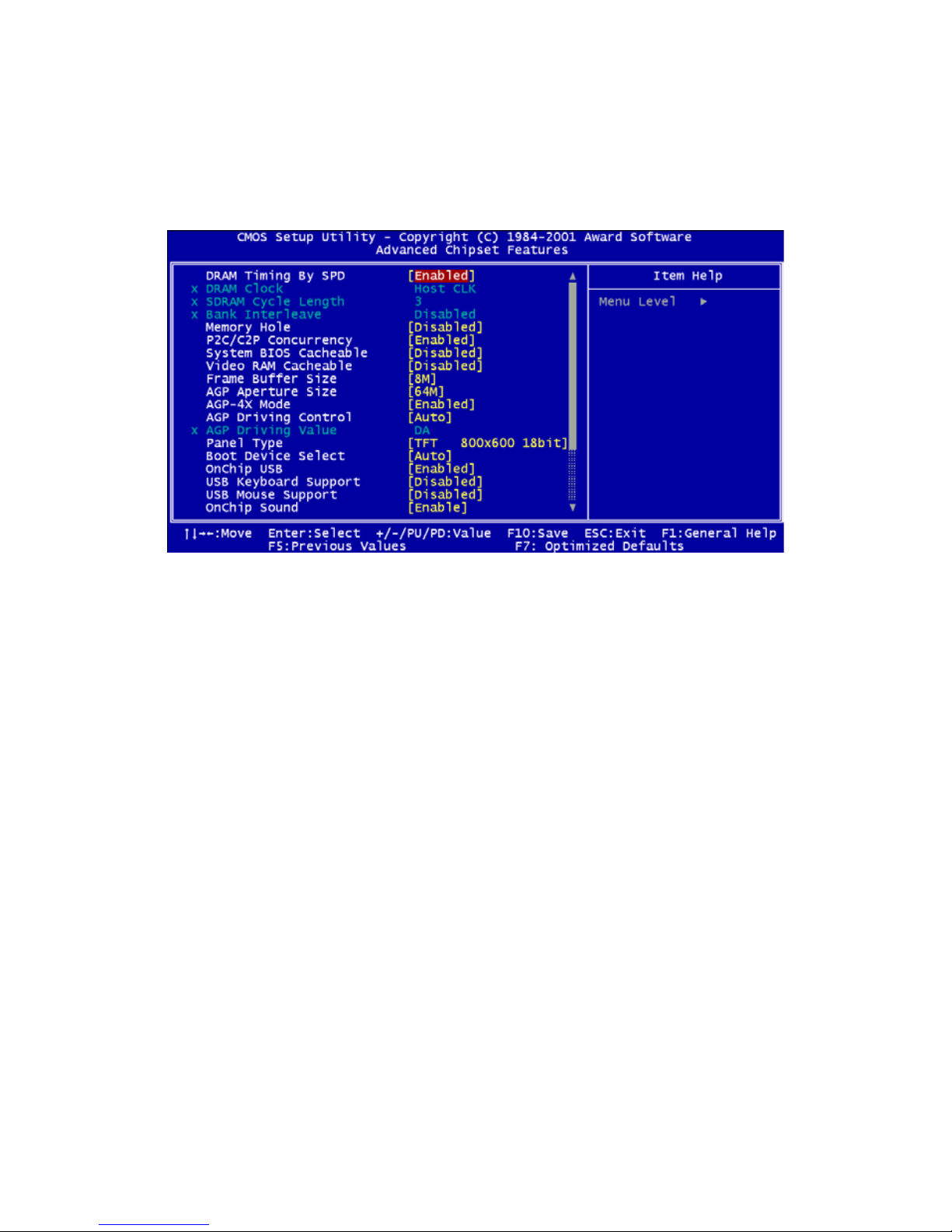
By choosing the Advanced Chipset Features option from the Initial Setup
Screen menu, the screen below is displayed. This sample screen contains
the manufacturer’s default values for the PCM-9373 Series.
Figure 4.4: Advanced Chipset Features setup
Page 47
37 Chapter 4
4.2.5 Integrated Peripherals
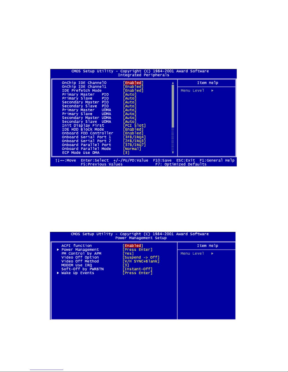
Choosing the Integrated Peripherals option from the Initial Setup Screen
menu should produce the screen below. Here we see the manufacturer’s
default values for the PCM-9373 Series.
4.2.6 Power Management Setup
By choosing the Power Management Setup option from the Initial Setup
Screen menu, the screen below is displayed. This sample screen contains
the manufacturer’s default values for the PCM-9373 Series.
Figure 4.5: Integrated Peripherals
Figure 4.6: Power Management Setup
Page 48
PCM-9373 User’s Manual 38
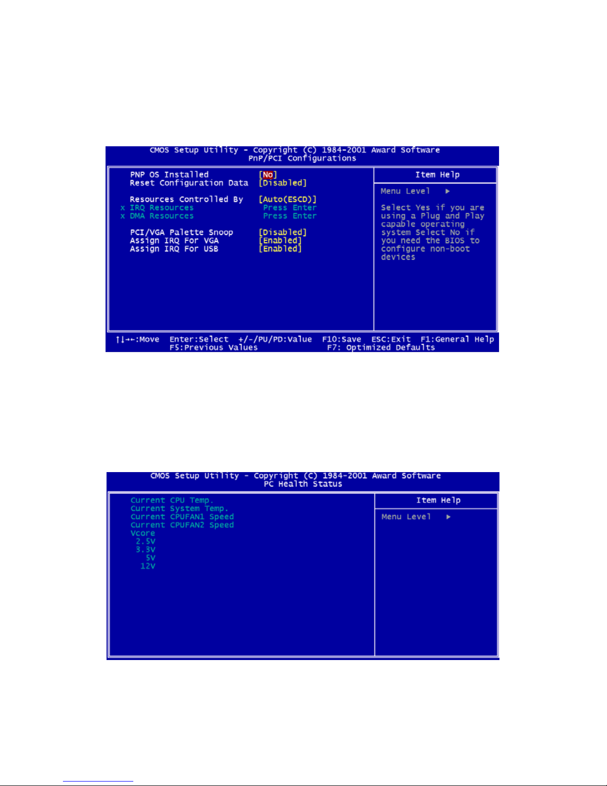
4.2.7 PnP/PCI Configurations
By choosing the PnP/PCI Configurations option from the Initial Setup
Screen menu, the screen below is displayed. This sample screen contains
the manufacturer’s default values for the PCM-9373 Series.
4.2.8 PC Health Status
The PC Health Status option displays information such as CPU and motherboard temperatures, fan speeds, and core voltage.
Figure 4.7: PnP/PCI Configurations
Figure 4.8: PC Health Status
Page 49
39 Chapter 4
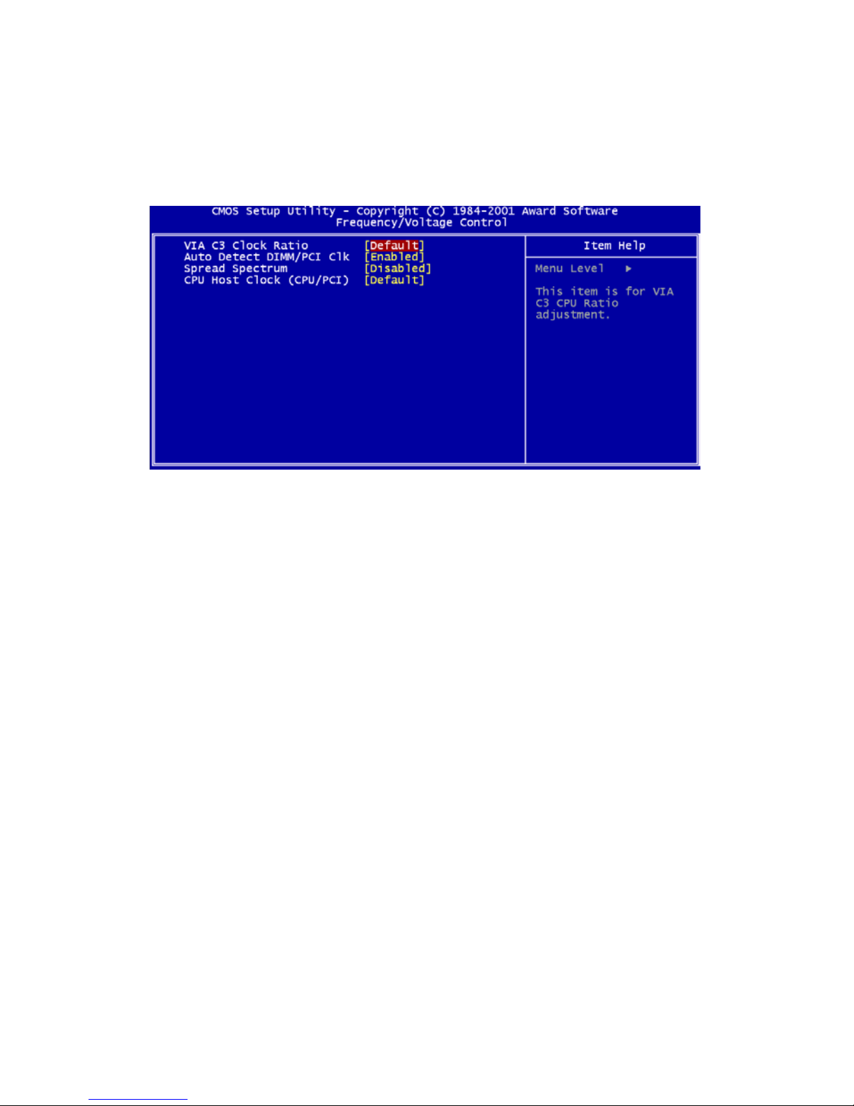
4.2.9 Frequency/Voltage Control
By choosing the Frequency/Voltage Control option from the Initial Setup
Screen menu, the screen below is displayed. This sample screen contains
the manufacturer’s default values for the PCM-9373
Figure 4.9: Frequency/Voltage Control
Caution Incorrect settings in Frequency/Voltage Control
may damage the system CPU, video adapter,
or other hardware.
Page 50
PCM-9373 User’s Manual 40
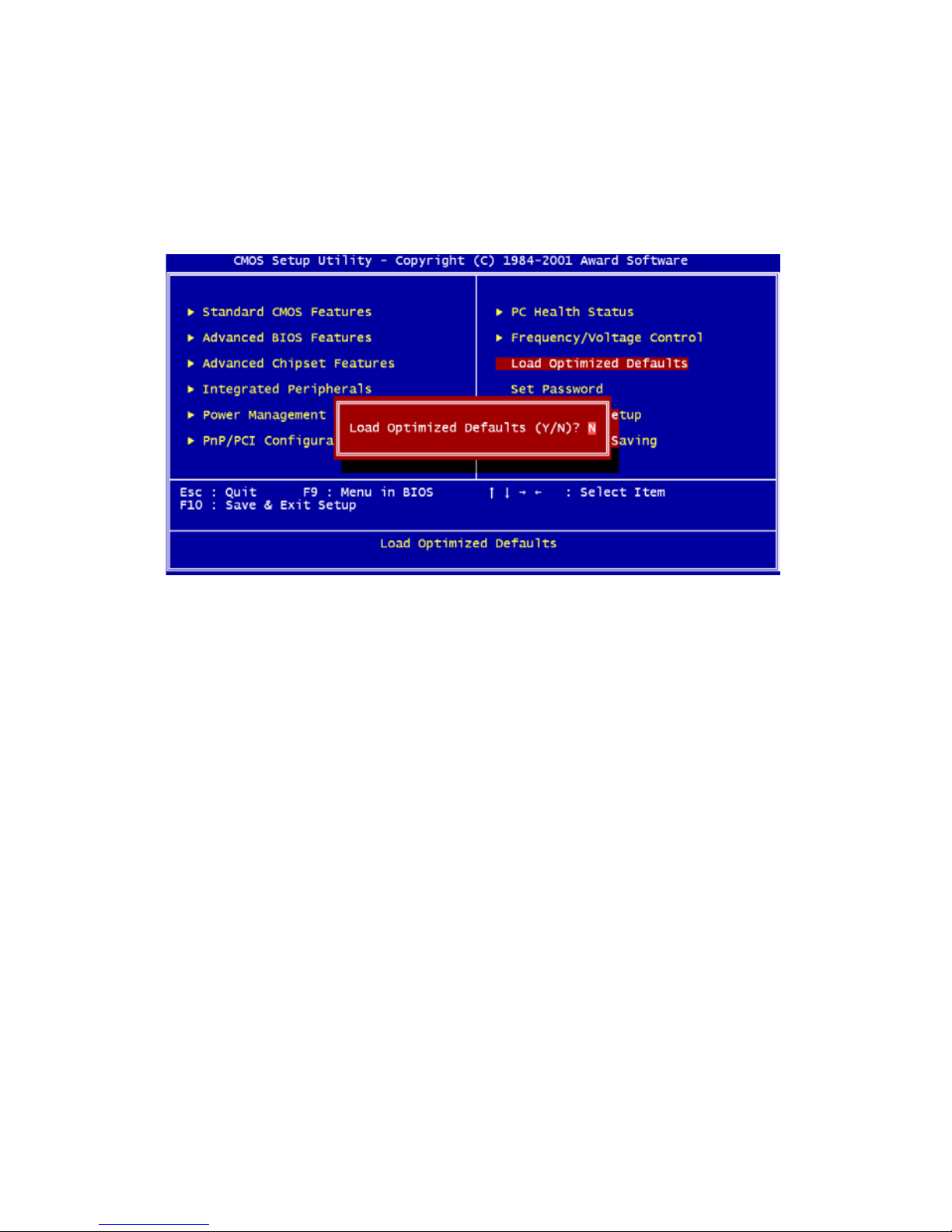
4.2.10 Load Optimized Defaults
Load Optimized Defaults loads the default system values directly from
ROM. If the stored record created by the Setup program should ever
become corrupted (and therefore unusable), these defaults will load automatically when you turn the PCM-9373 Series system on.
4.2.11 Set Password
To Establish Password
1. Choose the Set Password option from the CMOS Setup Utility
main menu and press <Enter>.
2. When you see “Enter Password,” enter the desired password and
press <Enter>.
Figure 4.10: Load BIOS defaults screen
Note To enable this feature, you should first go to the
Advanced BIOS Features menu, choose the
Security Option, and select either Setup or
System, depending on which aspect you want
password protected. Setup requires a password only to enter Setup. System requires the
password either to enter Setup or to boot the
system.
A password may be at most 8 characters long.
Page 51

41 Chapter 4
3. At the “Confirm Password” prompt, retype the desired password,
then press <Enter>.
4. Select Save to CMOS and EXIT, type <Y>, then <Enter>.
To Change Password
1. Choose the Set Password option from the CMOS Setup Utility
main menu and press <Enter>.
2. When you see “Enter Password,” enter the existing password and
press <Enter>.
3. You will see “Confirm Password.” Type it again, and press
<Enter>.
4. Select Set Password again, and at the “Enter Password” prompt,
enter the new password and press <Enter>.
5. At the “Confirm Password” prompt, retype the new password, and
press <Enter>.
6. Select Save to CMOS and EXIT, type <Y>, then <Enter>.
To Disable Password
1. Choose the Set Password option from the CMOS Setup Utility
main menu and press <Enter>.
2. When you see “Enter Password,” enter the existing password and
press <Enter>.
3. You will see “Confirm Password.” Type it again, and press
<Enter>.
4. Select Set Password again, and at the “Enter Password” prompt,
don’t enter anything; just press <Enter>.
5. At the “Confirm Password” prompt, again don’t type in anything;
just press <Enter>.
6. Select Save to CMOS and EXIT, type <Y>, then <Enter>.
4.2.12 Save & Exit Setup
If you select this option and press <Y> then <Enter>, the values entered
in the setup utilities will be recorded in the chipset’s CMOS memory. The
microprocessor will check this every time you turn your system on and
use the settings to configure the system. This record is required for the
system to operate.
Page 52

PCM-9373 User’s Manual 42
4.2.13 Exit Without Saving
Selecting this option and pressing <Enter> lets you exit the Setup program without recording any new values or changing old ones.
Page 53

CHAPTER
5
PCI SVGA Setup
• Introduction
• Installation of SVGA drivers
-for Windows 95/98/Me
-for Windows NT/2000/XP
• Further information
Page 54

PCM-9373 User’s Manual 44
Chapter 5 PCI SVGA Setup
5.1 Introduction
The PCM-9373 has an onboard AGP flat panel/VGA interface. The specifications and features are described as follows:
5.1.1 Chipset
The PCM-9373 uses a VIA Twister 8606T chipset from VIA Technology
Inc. for its AGP/SVGA controller. It supports many popular LCD, and
LVDS LCD displays and conventional analog CRT monitors. The
VIA8606T VGA BIOS supports color TFT and DSTN LCD flat panel
displays. In addition, it also supports interlaced and non-interlaced analog
monitors (color and monochrome VGA) in high-resolution modes while
maintaining complete IBM VGA compatibility. Digital monitors
(i.e. MDA, CGA, and EGA) are NOT supported. Multiple frequency
(multisync) monitors are handled as if they were analog monitors.
5.1.2 Display memory
The Twister chip can support 8/16/32MB frame buffer shared with system memory; the VGA controller can drive CRT displays or color panel
displays with resolutions up to 1280 x 1024 at 16 M colors.
5.1.3 Display types
CRT and panel displays can be used simultaneously. The PCM-9373 can
be set in one of three configurations: on a CRT, on a flat panel display, or
on both simultaneously. The system is initially set to simultaneous display mode. If you want to enable the CRT display only or the flat panel
display only, please contact VIA Technology Inc., or our sales representative for detailed information.
5.1.4 Dual/Simultaneous Display
The PCM-9373 uses a VIA Twister VT8606T LCD controller that is
capable of providing simultaneous dual view display of the same content
on a flat panel and CRT.
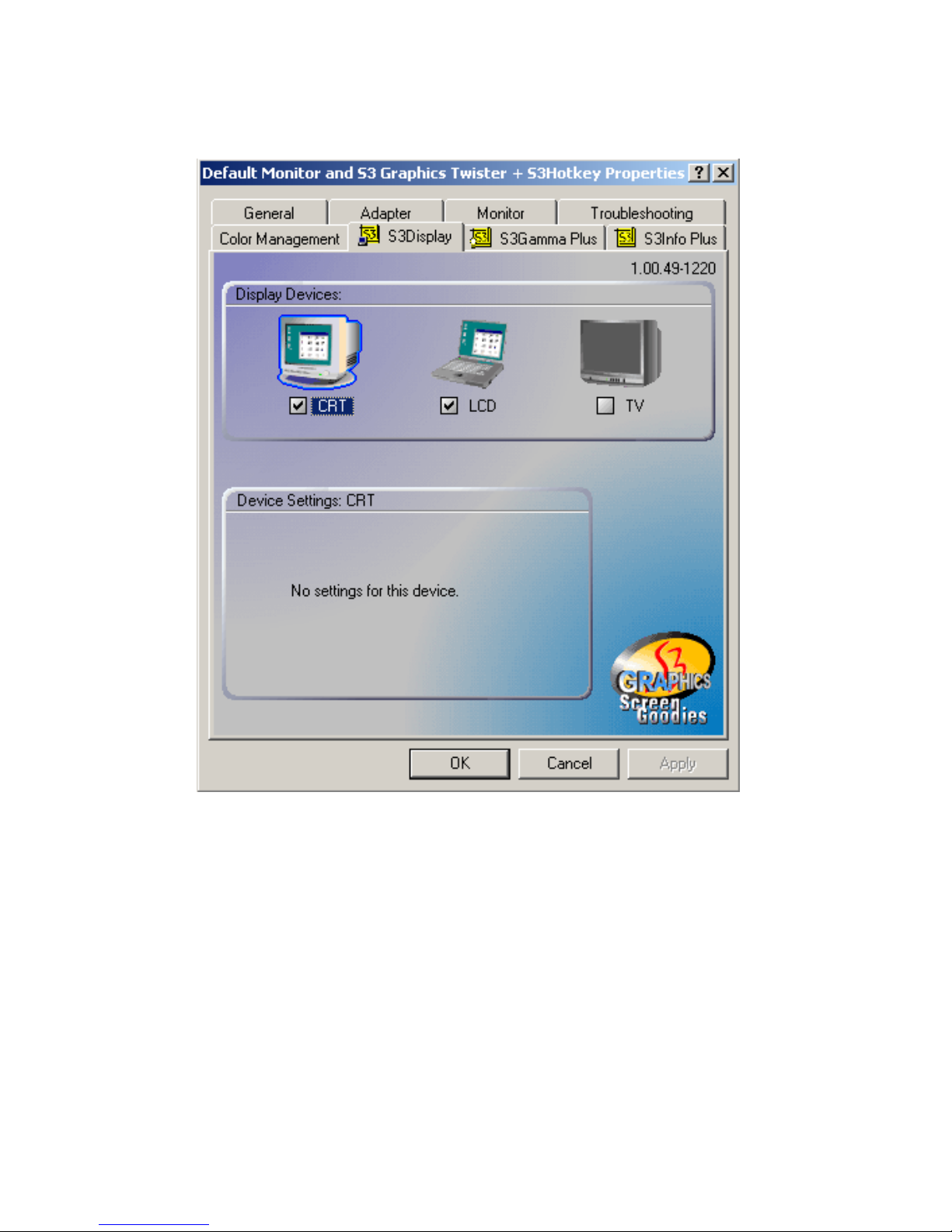
To set up dual view (simultaneus mode) under Windows 9x, Windows
ME, Windows NT/2000/XP, follow these steps:
1. Open the Control panel, and select “Display”, “Settings”.
2. Select " CRT+LCD " or " CRT+TV " for dual view
Page 55
45 Chapter 5
3. Click “OK”.
Figure 5.1: Selecting Display Settings
Page 56
PCM-9373 User’s Manual 46
5.2 Installation of the SVGA Driver
Complete the following steps to install the SVGA driver. Follow the procedures in the flow chart that apply to the operating system that you are
using within your PCM-9373.
5.2.1 Installation for Windows 95
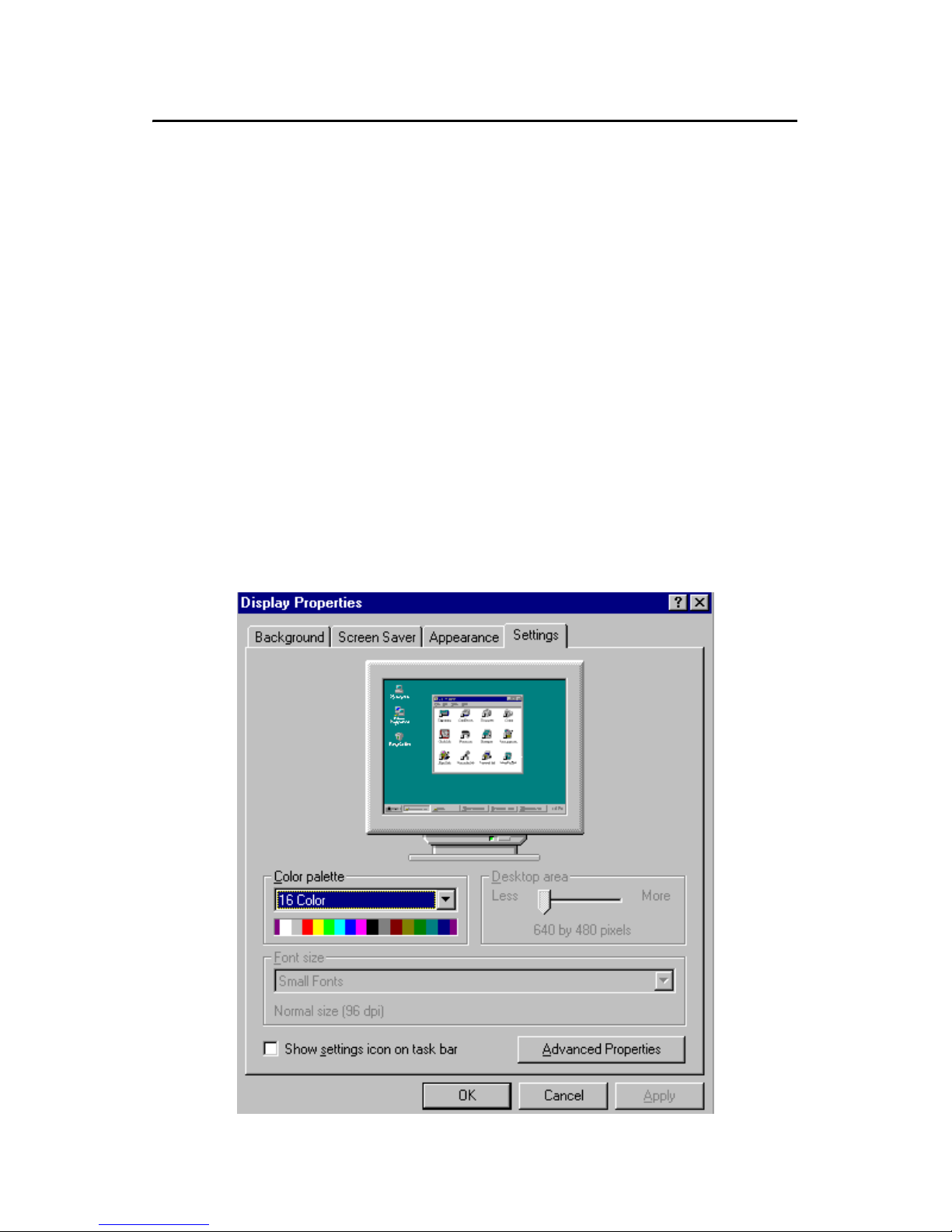
1. Select "Start", "Settings", "Control Panel", "Display", "Settings”,
and "Advanced Properties".
Notes:
1. The windows illustrations in this chapter are
intended as examples only. Please follow the
listed steps, and pay attention to the instructions which appear on your screen.
2. For convenience, the CD-ROM drive is designated as "D" throughout this chapter.
Page 57
47 Chapter 5
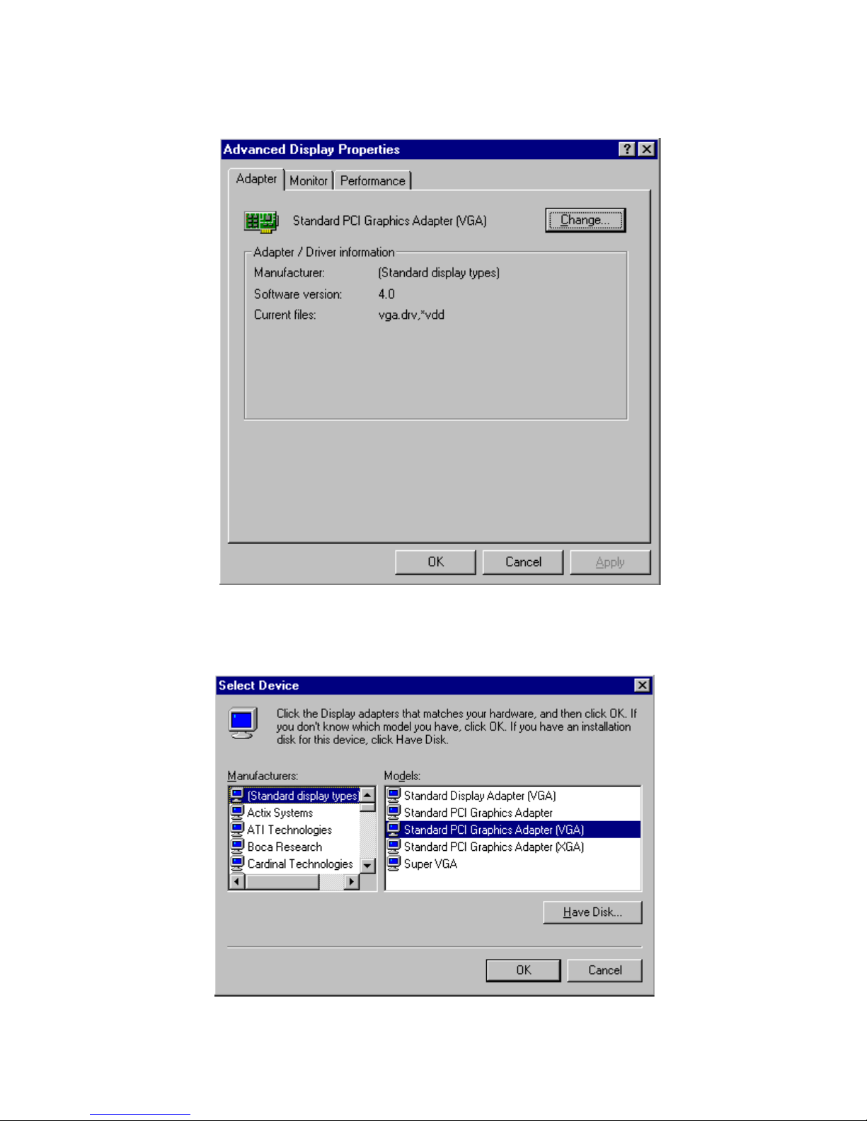
2. Choose the "Adapter" tab, then press the "Change..." button.
3. Press the "Have Disk" button.
Page 58
PCM-9373 User’s Manual 48
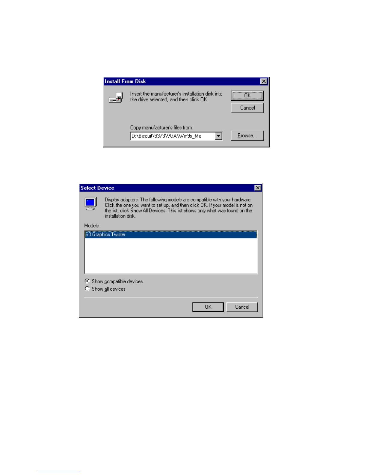
4. Type in the path:
D:\Biscuit\9373\VGA\Win9x_Me
5. Select the highlighted item, and click the "OK" button.
Page 59
49 Chapter 5
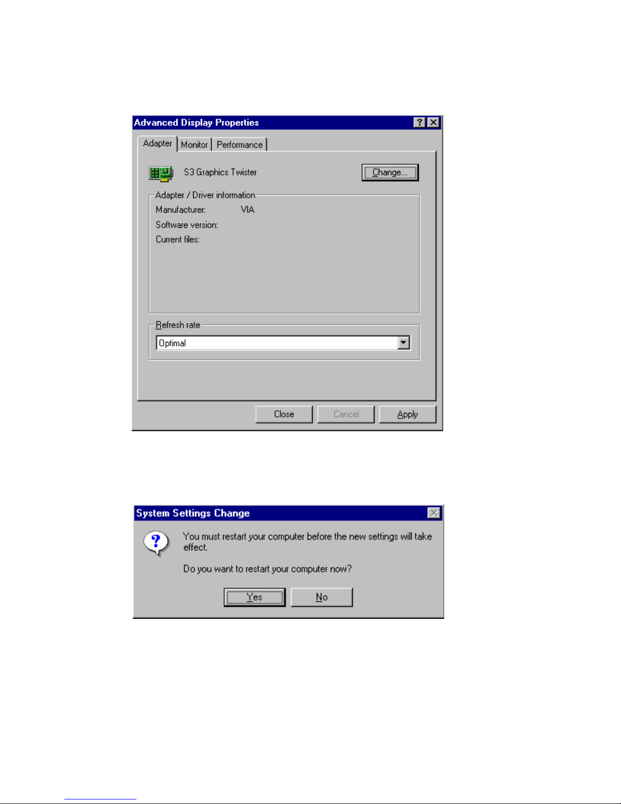
6. "S3 GraphicsTwister" appears under the adapter tab. Click the
"Apply" button, then the "OK" button.
7. Press “Yes” to reboot.
Page 60
PCM-9373 User’s Manual 50
5.2.2 Installation for Windows 98/Me
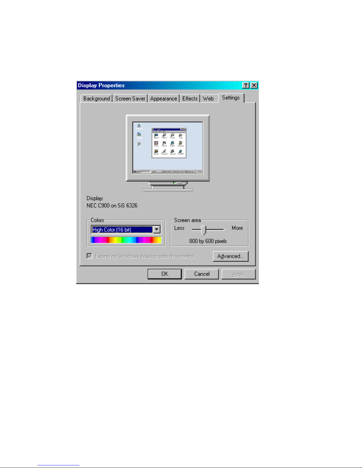
1. Select "Start", "Settings", "Control Panel", "Display", and "Set-
tings," then press the "Advanced..." button.
Page 61
51 Chapter 5
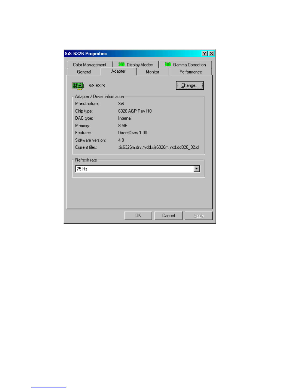
2. Select “Adapter,” then “Change.”
Page 62
PCM-9373 User’s Manual 52
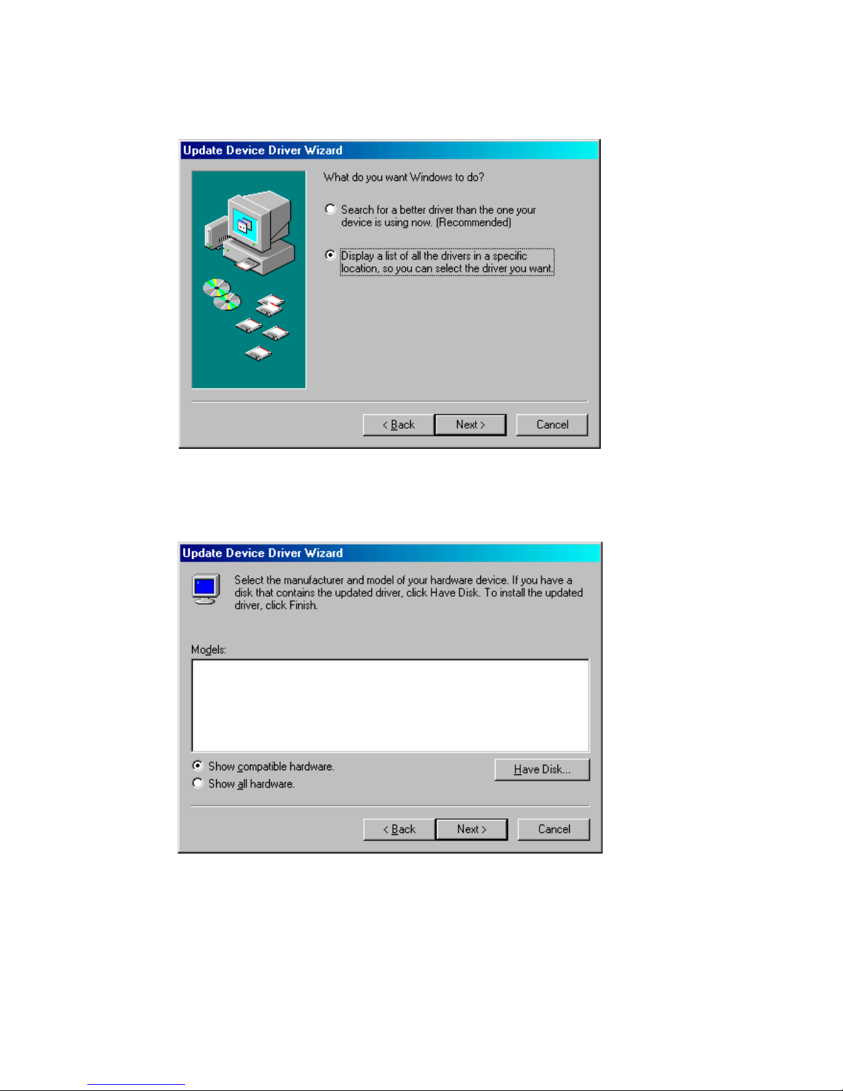
3. Press “Next,” then “Display a list....”
4. Press the “Have disk...” button.
Page 63
53 Chapter 5
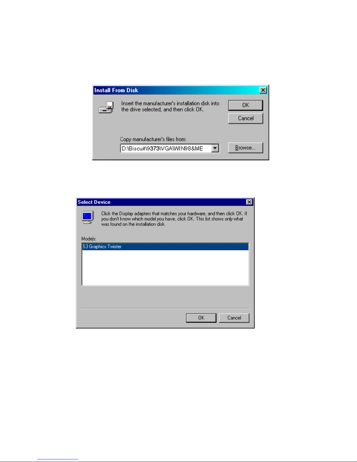
5. Insert the CD into the CD-ROM drive. Type in the path
D:\Biscuit\9373\VGA\Win9x_Me
Then press “OK”
6. Select the highlighted item, then click “OK.”
Page 64
PCM-9373 User’s Manual 54
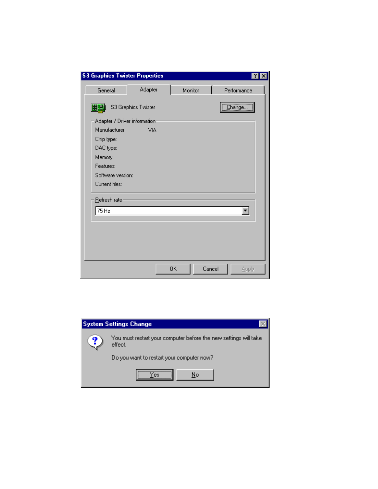
7. "S3 Graphics Twister"appears under the adapter tab. Click the
"Apply" button.
8. Press “Yes” to reboot.
Page 65
55 Chapter 5
5.2.3 Installation for Windows NT
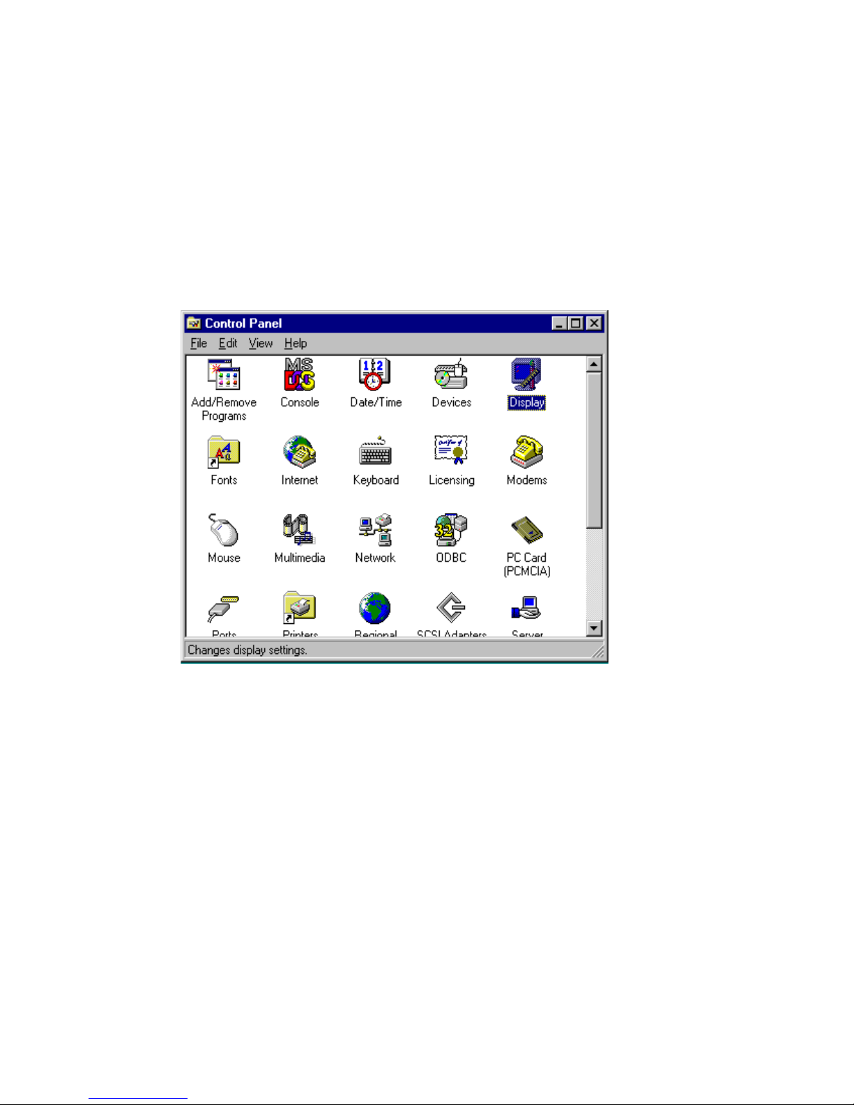
1. Select "Start", "Settings", "Control Panel" and double click the
"Display" icon.
Note:
Service Pack X (X = 3, 4, 5, 6,...) must be
installed first, before you install the Windows
NT VGA driver.
Page 66
PCM-9373 User’s Manual 56
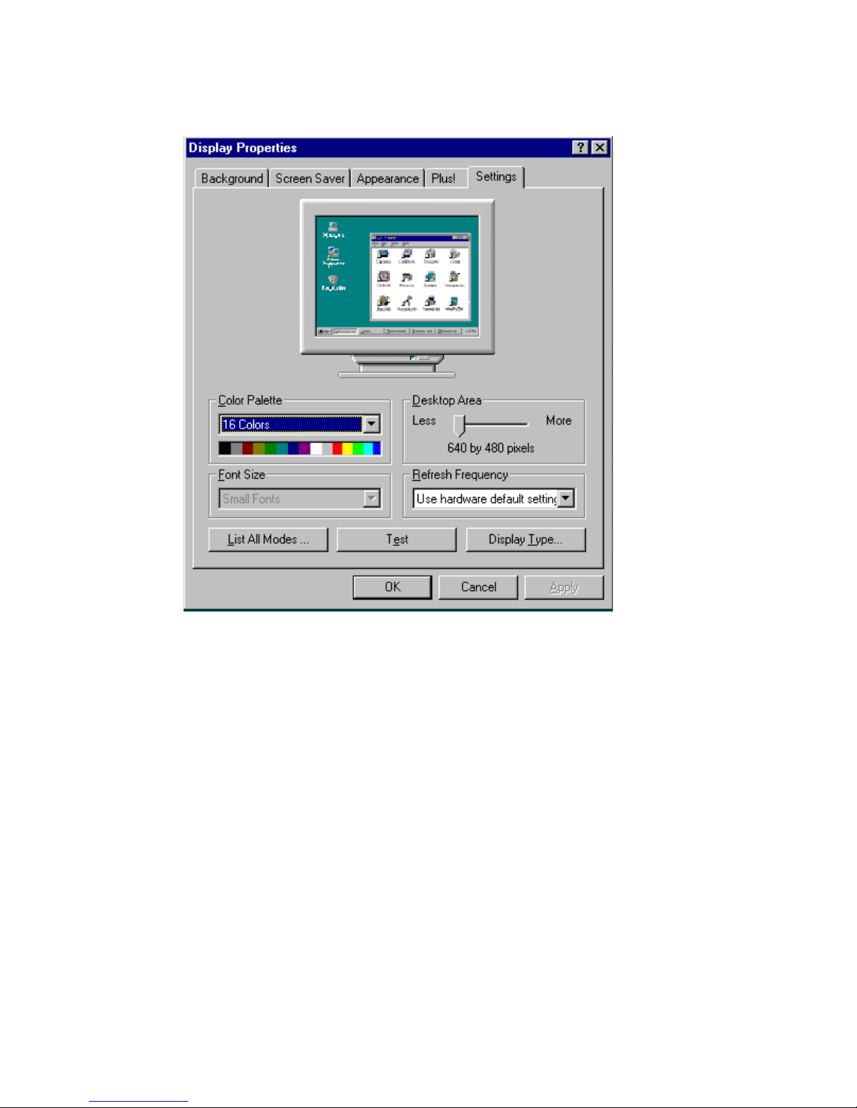
2. Choose the "Settings" tab, and press the "Display Type" button.
Page 67
57 Chapter 5
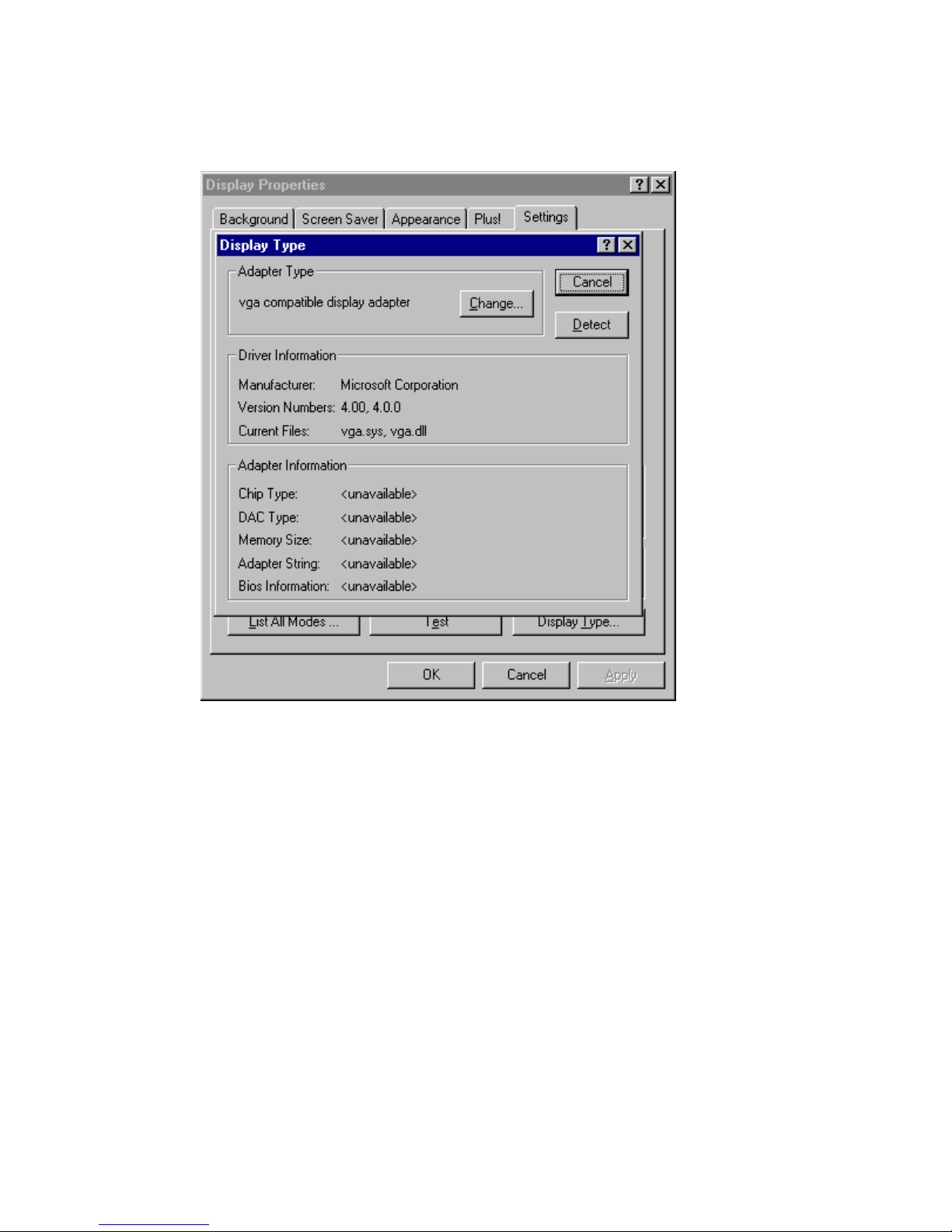
3. Press the "Change..." button.
Page 68
PCM-9373 User’s Manual 58
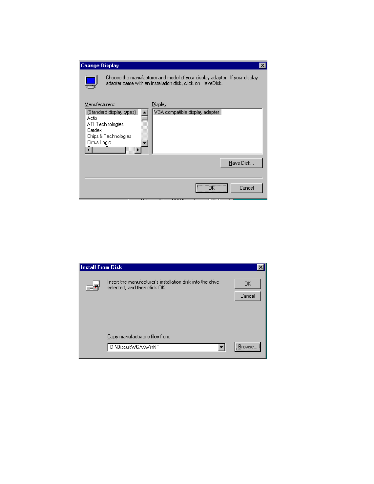
4. Click the "Have Disk..." button.
5. Type the path:
D:\Biscuit\VGA\WinNT
Press the "OK" button.
Page 69
59 Chapter 5
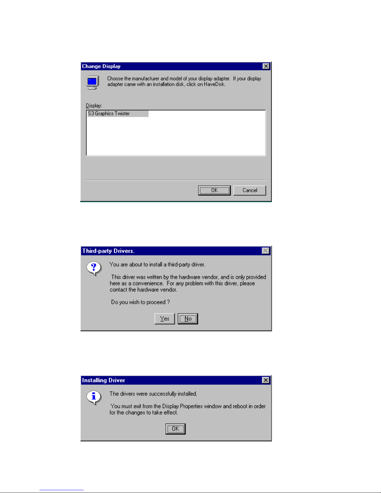
6. Select the highlighted item, and click the "OK" button.
7. Press "Yes" to proceed.
8. Press "OK" to reboot.
Page 70
PCM-9373 User’s Manual 60
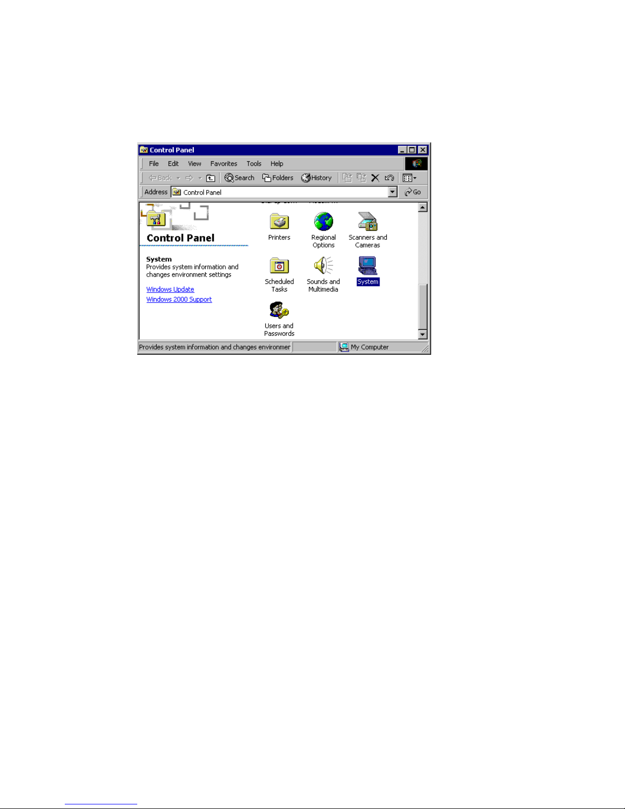
5.2.4 Installation for Windows 2000
1. Select "System", "Settings", "Control Panel" and double click the
"system" icon.
Page 71
61 Chapter 5
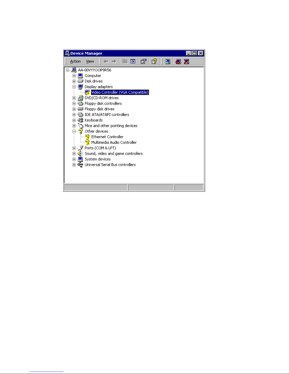
2. Choose the "Video Controller (VGA Compatible)” button.
Page 72
PCM-9373 User’s Manual 62
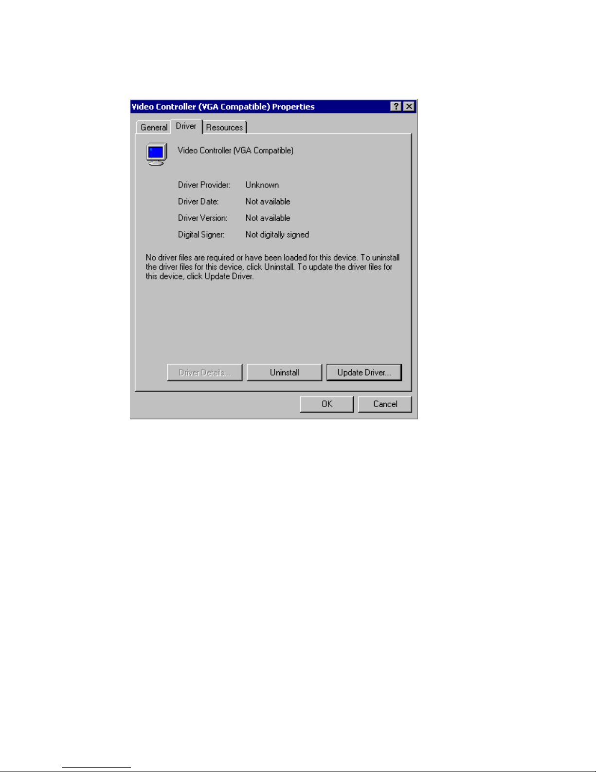
3. Choose the "Drive" button, press “Update Driver...” button.
Page 73
63 Chapter 5
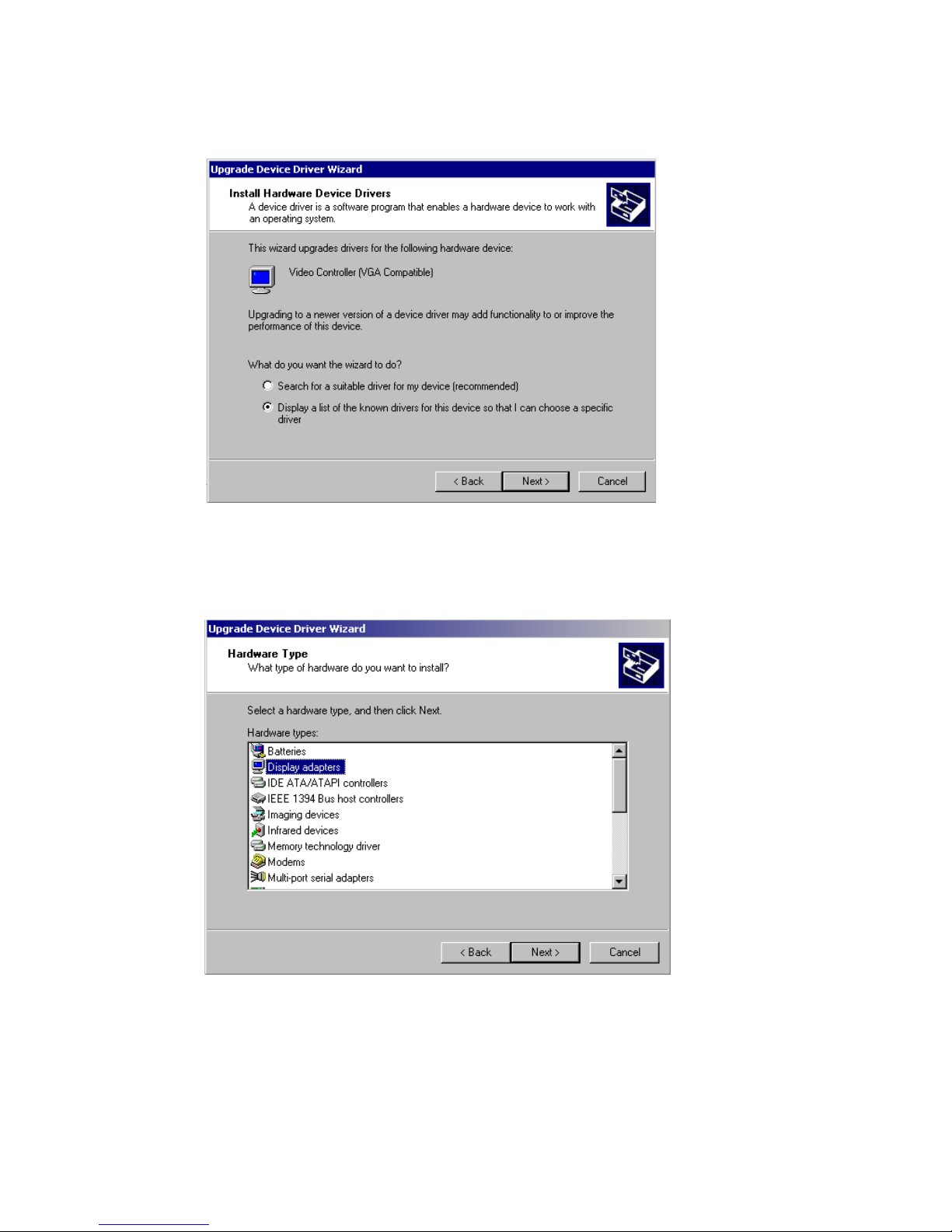
4. Choose "Display a list of..." , then press “Next” button.
5. Choose “Display adapters”, press “Next” button.
Page 74
PCM-9373 User’s Manual 64
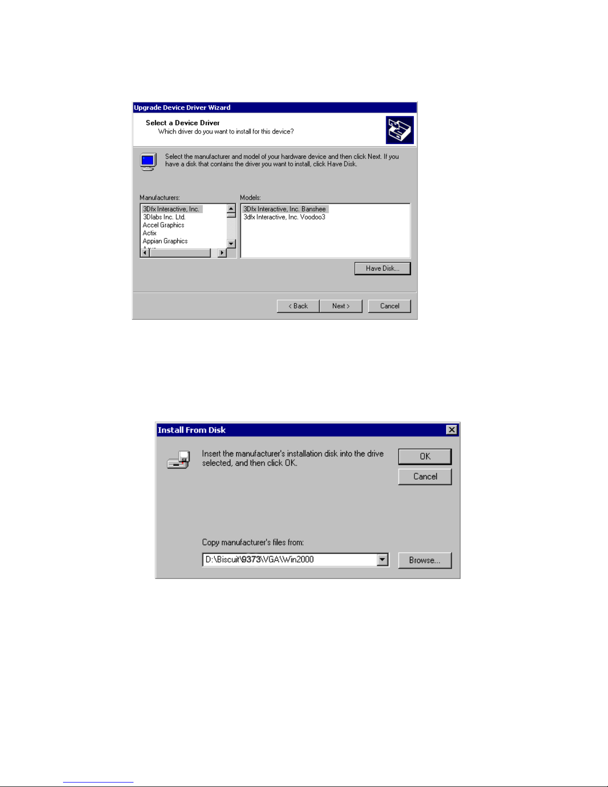
6. Click the “Have Disk” button.
7. Type the path D:\Biscuit\9373\VGA\Win2000 press the “OK” but-
ton.
Page 75
65 Chapter 5
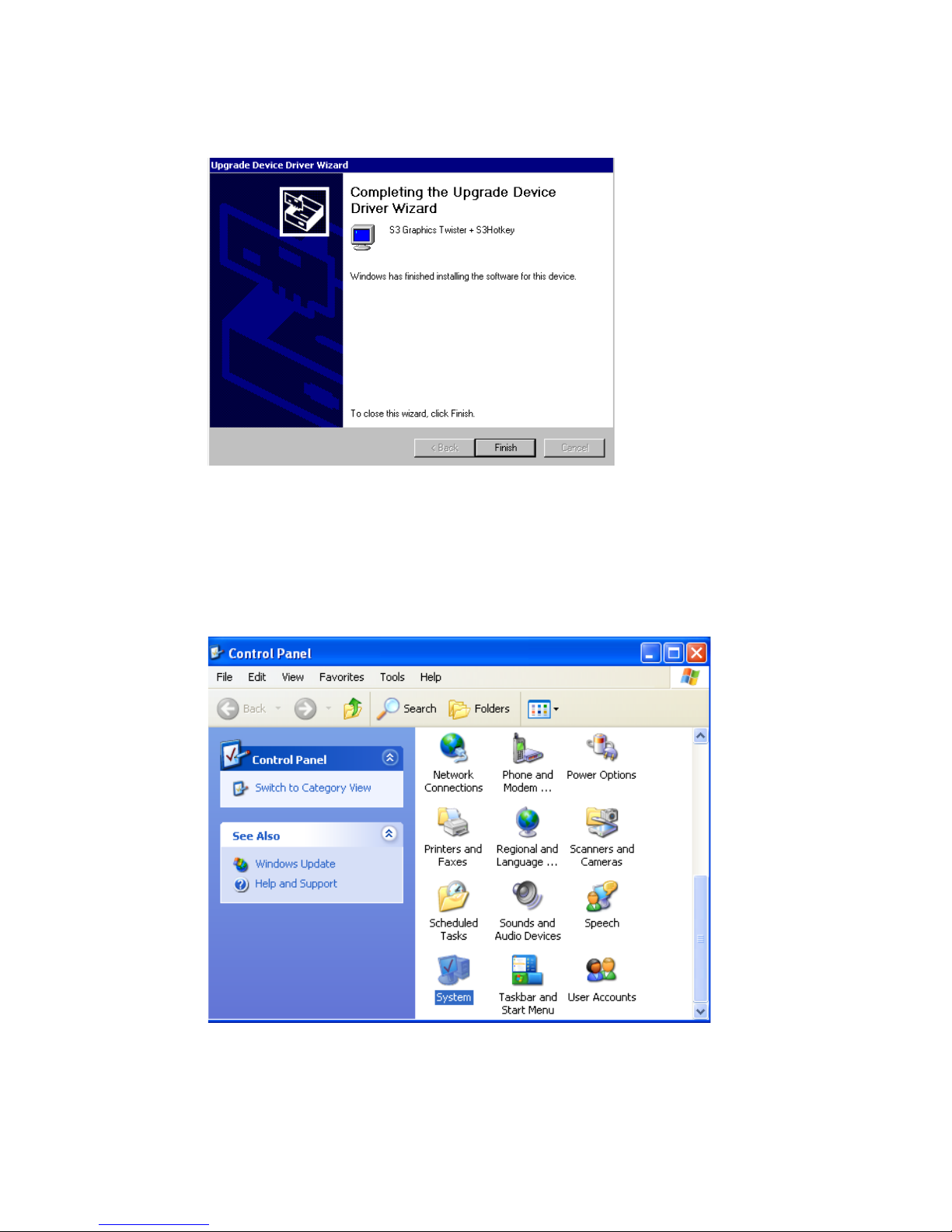
8. Press “Finish" to reboot.
5.2.5 Installation for Windows XP
1. Select "System", "Settings", "Control Panel" and double click the
"system" icon.
Page 76
PCM-9373 User’s Manual 66
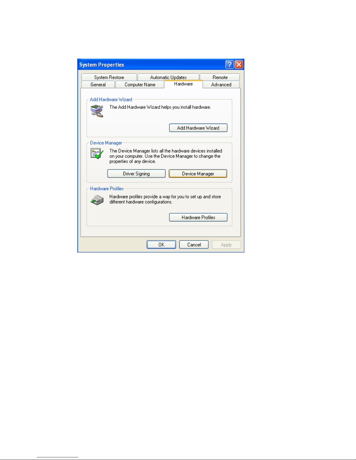
2. Choose “Hardware” and “Device Manager”, press “OK” button.
Page 77
67 Chapter 5
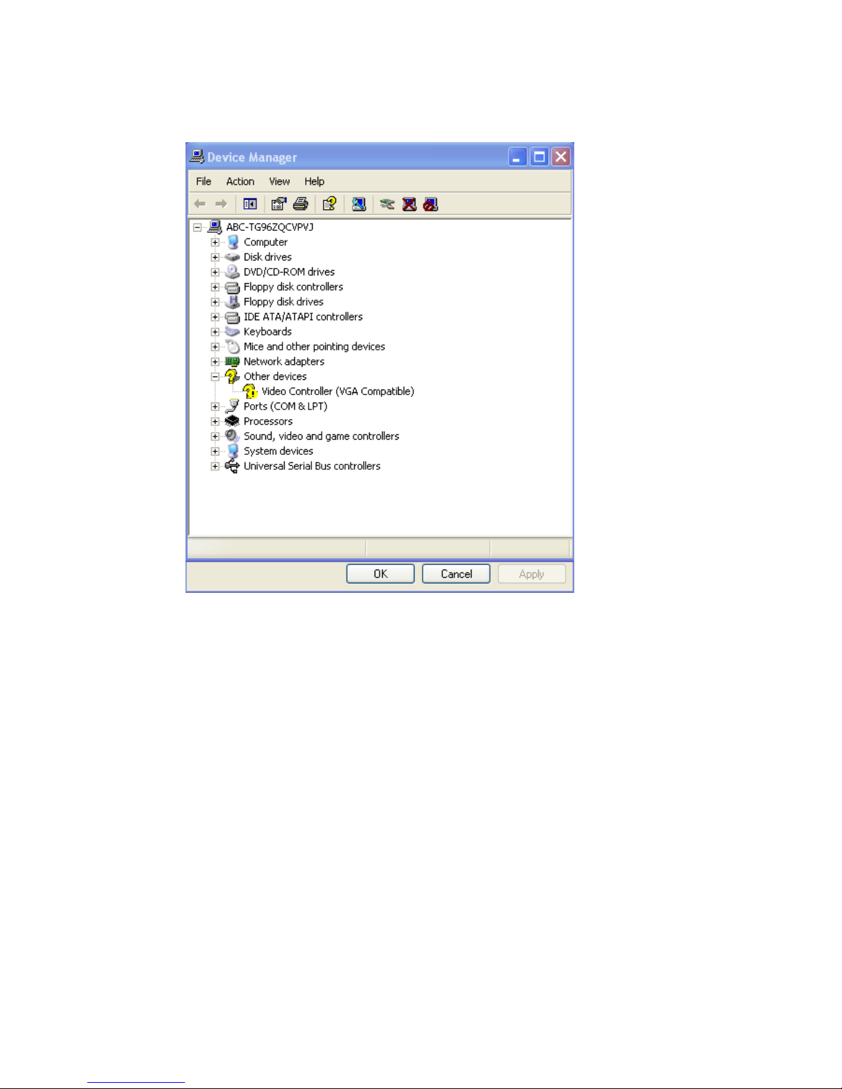
3. Choose “Video Controller (VGA Compatible), press “OK” button.
Page 78
PCM-9373 User’s Manual 68
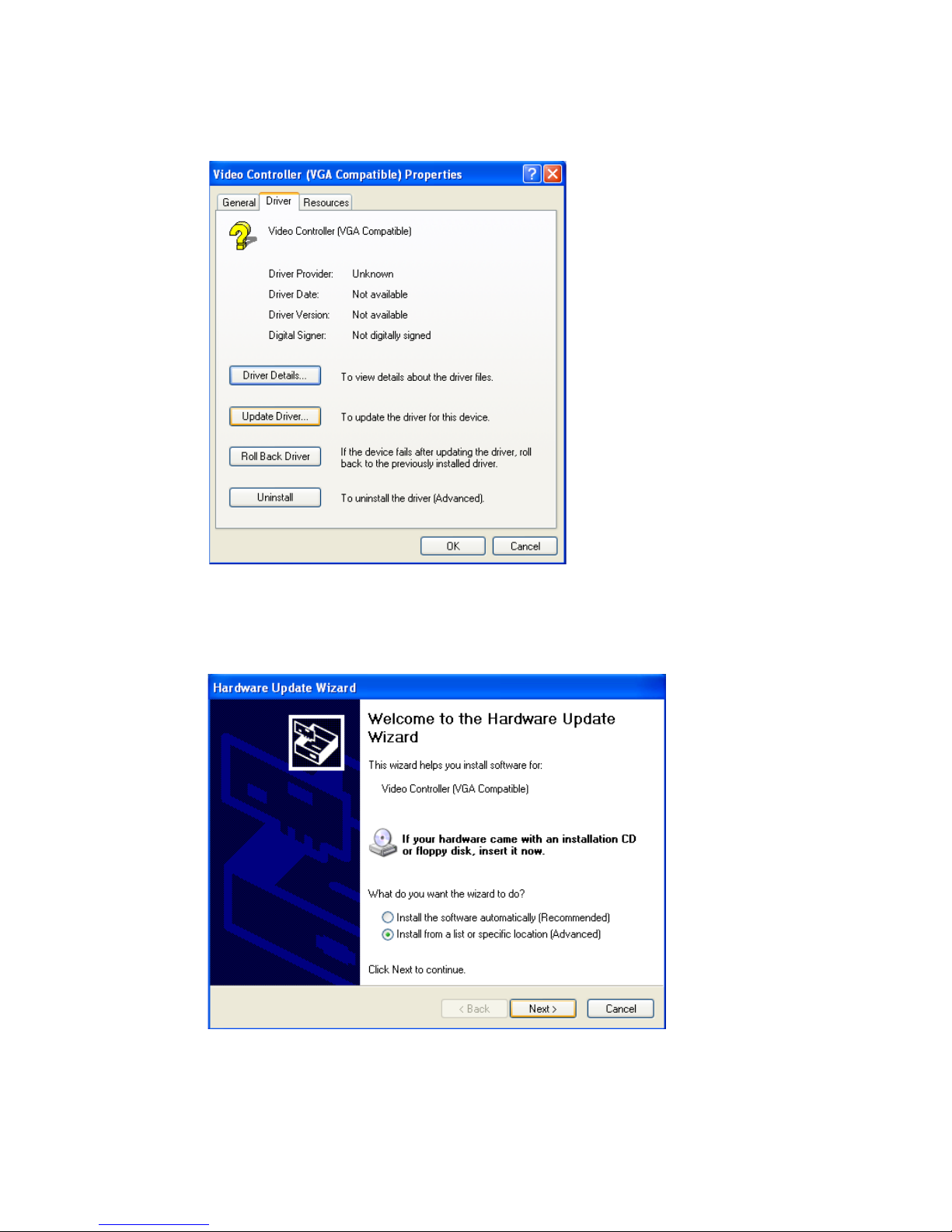
4. Choose "Driver”, “Update Driver”, press “OK” button.
5. Choose “Install from a list.....” , press “Next”.
Page 79
69 Chapter 5
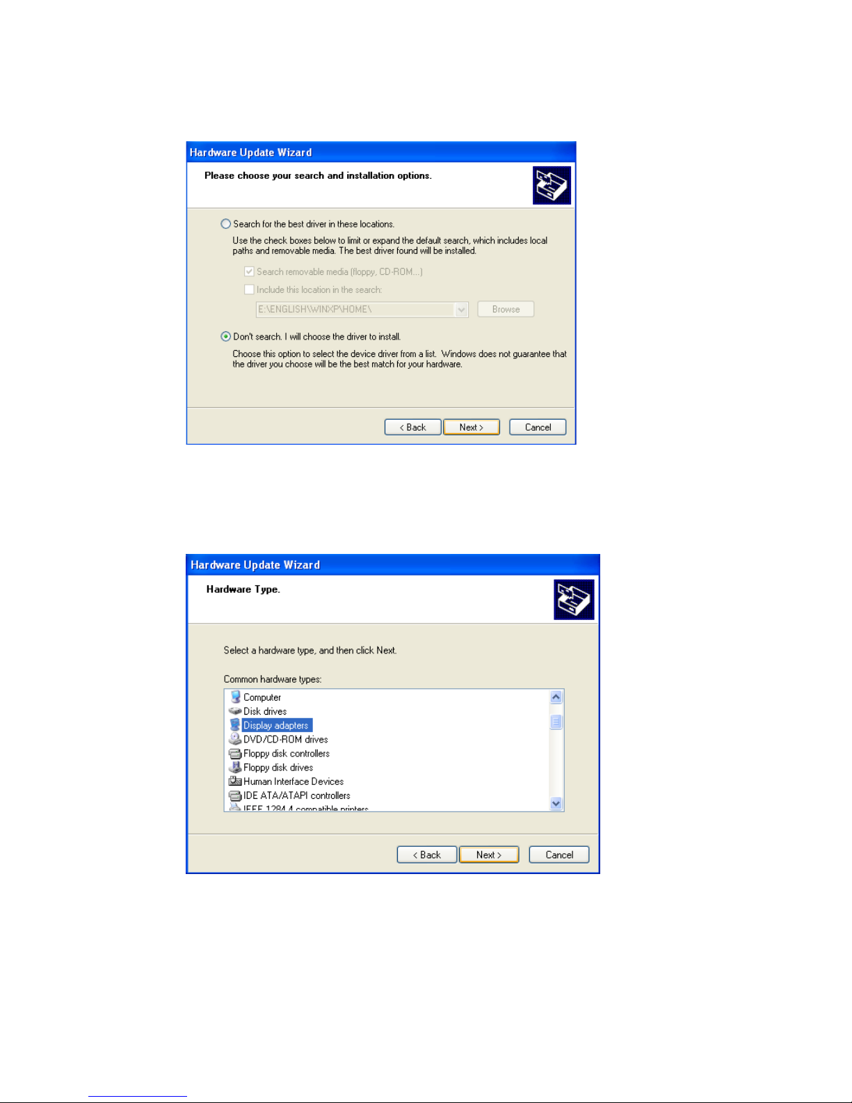
6. Choose “Don’t search. I will....”, press “Next” button.
7. Choose “Display adapters”, press “Next” button.
Page 80
PCM-9373 User’s Manual 70
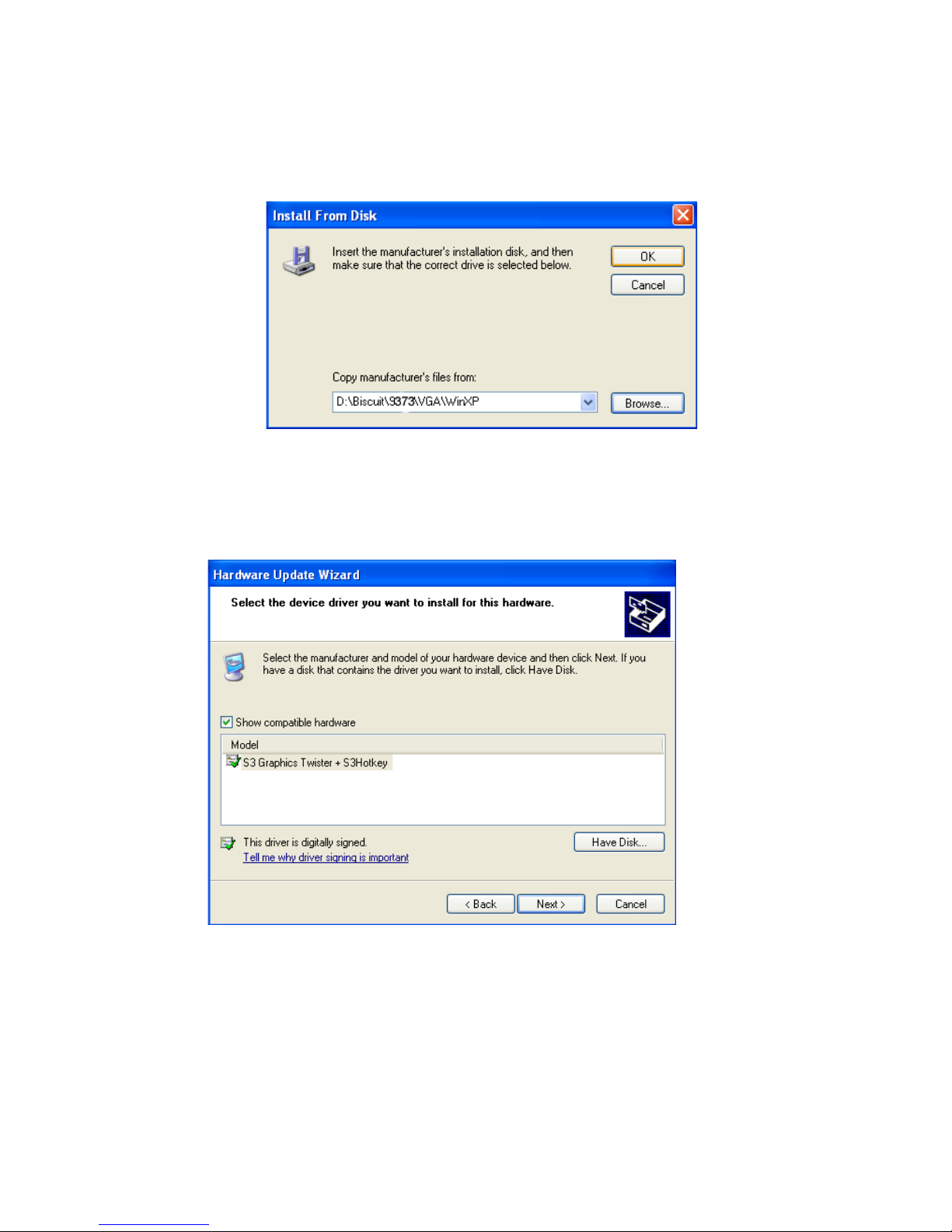
8. Type the path D:\Biscuit\9373\VGA\WinXP then press “OK” but-
ton.
9. Choose “S3 Graphics Twister + S3 Hotkey” then press “Next” but-
ton.
Page 81
71 Chapter 5
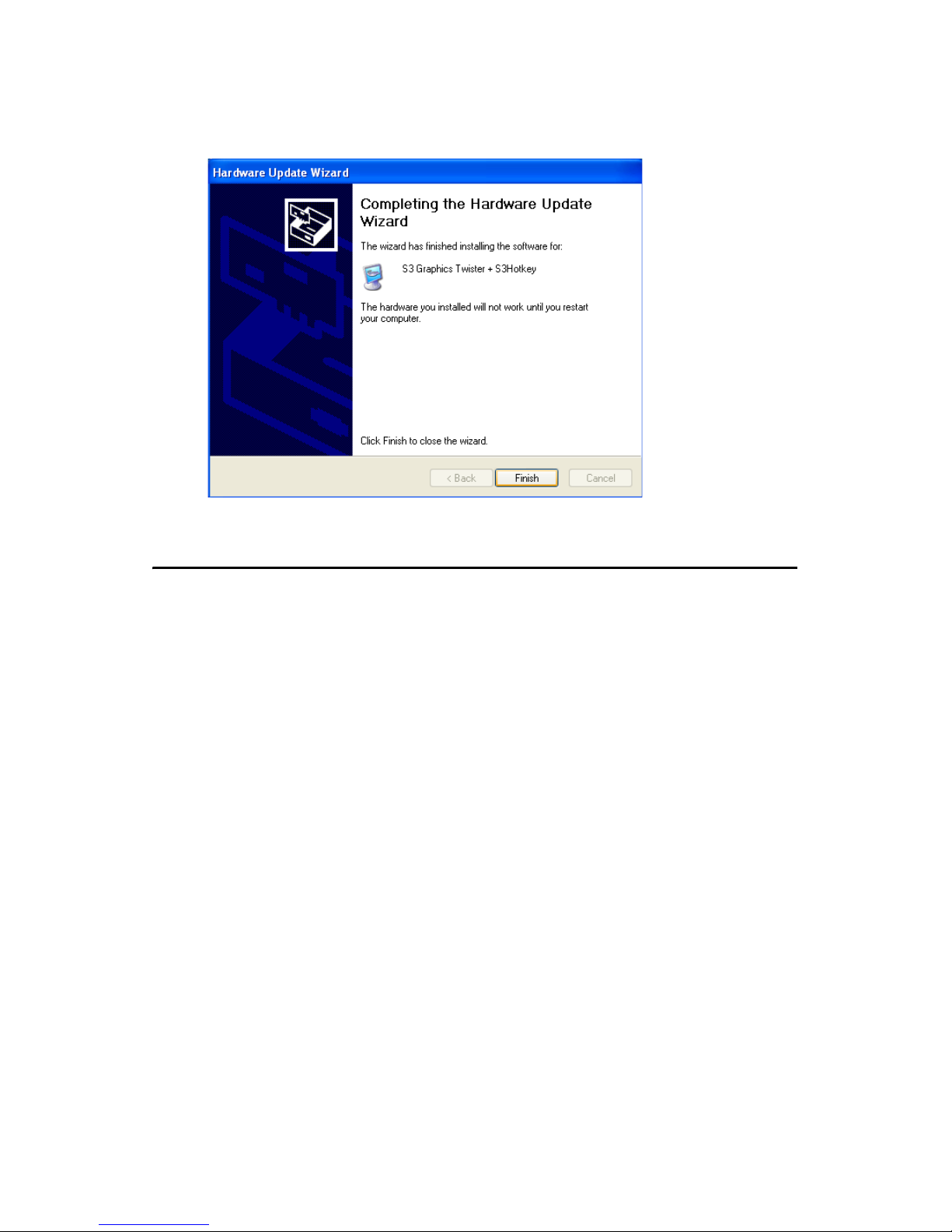
10. Press “Finish" to reboot.
5.3 Further Information
For further information about the AGP/VGA installation in your PCM9373, including driver updates, troubleshooting guides and FAQ lists,
visit the following web resources:
VIA website: www.via.com.tw
Page 82

PCM-9373 User’s Manual 72
Page 83

CHAPTER
6
Audio Setup
The PCM-9373 is equipped with an
audio interface that records and plays
back CD-quality audio. This chapter
provides instructions for installing the
software drivers included on the audio
driver diskettes.
Page 84

PCM-9373 User’s Manual 74
Chapter 6 Audio Setup
6.1 Introduction
The PCM-9373's on-board audio interface provides high-quality stereo
sound and FM music synthesis (ESFM) by using the VIA VT82C686
audio controller from VIA. The audio interface can record, compress, and
play back voice, sound, and music with built-in mixer control.
The PCM-9373 on board audio interface also supports the Plug and Play
(PnP) standard and provides PnP configuration for the audio, FM, and
MPU-104 logical devices. It is compatible with Sound Blaster™; Sound
Blaster Pro™ version 3.01, voice and music functions. The ESFM synthesizer is register compatible with the OPL3 and has extended capabilities.
6.2 DOS utilities
6.2.1 VIA Sound Blaster Pro compatible set up program
Please "Enable" the Sound Blaster setting in the BIOS before playing
Sound Blaster compatible DOS games. To enable the settings in the
BIOS:
INTEGRATED PERIPHERALS -> Onboard Legacy Audio
-> Sound Blaster (Disable -> Enable)
Chipset Feature Setup->On Chip Sound (Disable-> Enable)
The Sound Blaster Pro compatible sound chip is integrated into the VIA
PCI audio device in order to have Sound Blaster compatible DOS games
running on the system.
If you want to play Sound Blaster compatible DOS games under the real
mode MS-DOS or the "Restart in MS-DOS" from Win9x, then you
should run this setup program to enable OPL3 MIDI music. Otherwise,
the sound effects will be heard, but not the music. If you want to play legacy games in a Windows DOS Box, then you don't need to install this
program.
6.2.2 VIA Sound Blaster Installation
Follow these steps to enable the Sound Blaster Pro compatible functions.
1. Enable the Sound Blaster first on the BIOS setting of the "Onboard
Legacy Audio" and "On-Chip Sound".
Page 85

75 Chapter 6
2. Run the "Install.exe".
A:> INSTALL
3. The program will copy the relative files into the directory which
you assign. Next, the program will insert the following new line
into the AUTOEXEC.BAT and copy the original
AUTOEXEC.BAT to AUTOEXEC.VIA.
C: \VIAUDIO\VIAUDIO.COM
4. Reboot the system when the installation is complete.
5. Uninstall by deleting the new line from the AUTOEXEC.BAT.
6.3 Driver installation
6.3.1 Before you begin
Please read the instructions in this chapter carefully before you attempt
installation. The audio drivers for the PCM-9373 board are located on the
audio driver CD. Run the supplied SETUP program to install the drivers;
don’t copy the files manually.
Note:
The files on the software installation diskette
are compressed. Do not attempt to install the
drivers by copying the files manually. You must
use the supplied SETUP program to install the
drivers.
Page 86
PCM-9373 User’s Manual 76
6.3.2 Windows 95/98 drivers
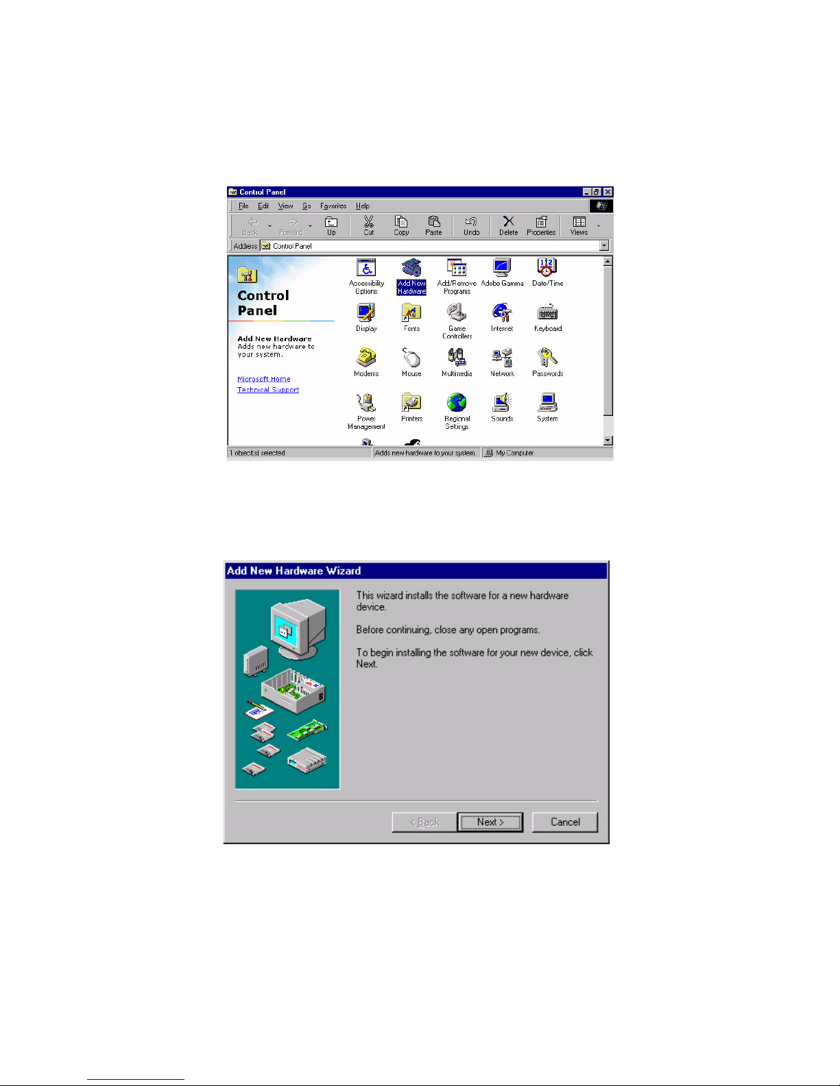
1. Click "Start" and select "Settings". Click "Control Panel" and dou-
ble-click "Add New Hardware".
2. In the Add New Hardware Wizard window, click "Next".
Page 87
77 Chapter 6
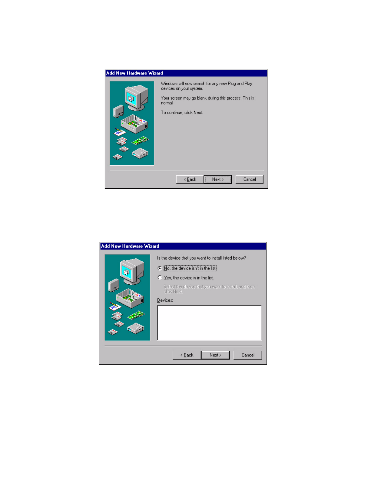
3. In the following Add New Hardware Wizard window, click "Next"
for Windows to search for Plug and Play devices.
4. In the following Add New Hardware Wizard window, select "No,
the device isn't in the list."and click "Next".
Page 88
PCM-9373 User’s Manual 78
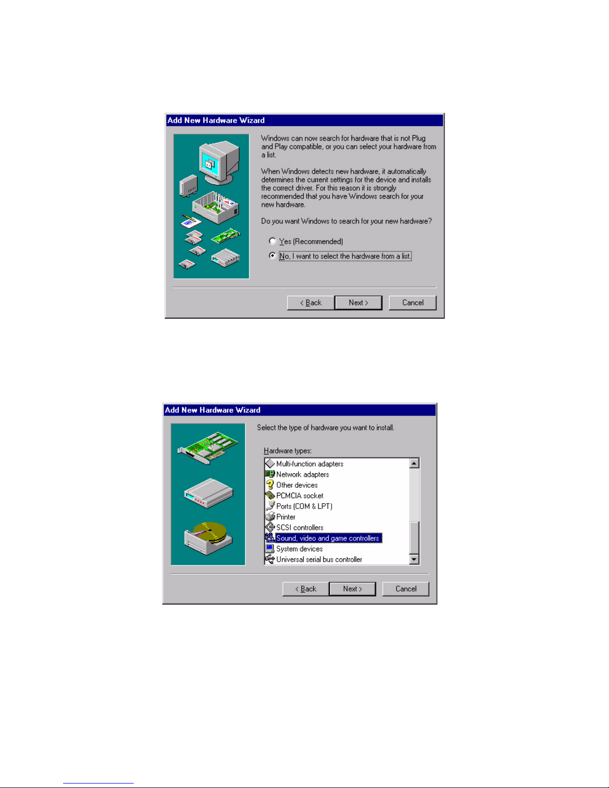
5. In the following Add New Hardware Wizard window, select "No, I
want to select..." and click "Next".
6. In the following Add New Hardware Wizard window, select
"Sound, video and game controllers" and click "Next".
Page 89
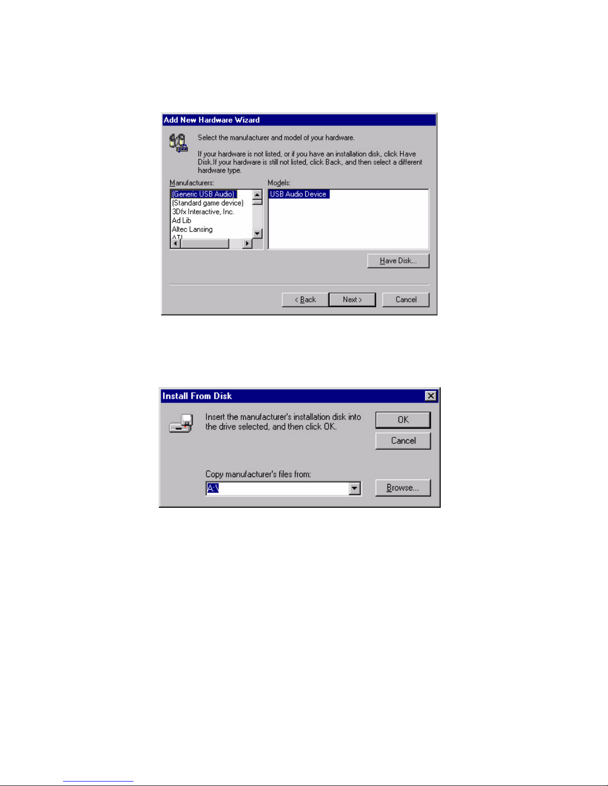
79 Chapter 6
7. In the following Add New Hardware Wizard window, click "Have
Disk...".
8. In the Install From Disk window, click "Browse".
Page 90
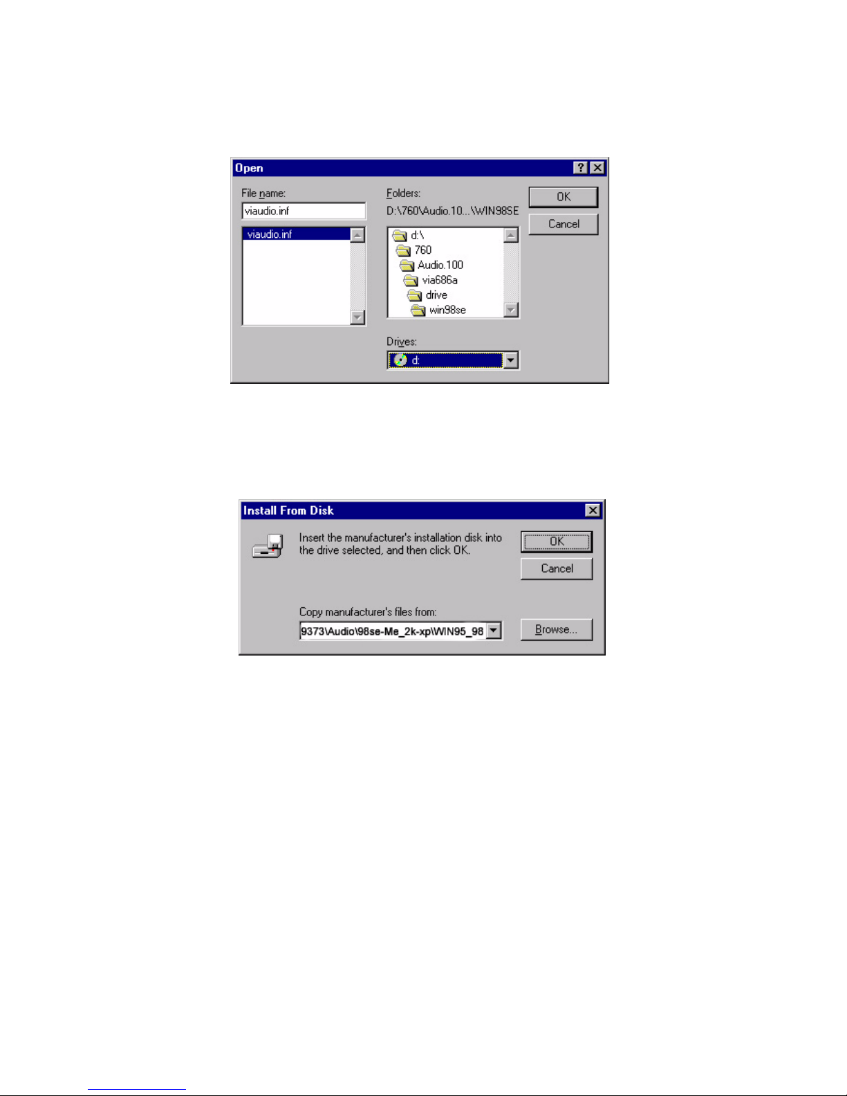
PCM-9373 User’s Manual 80
9. In the Open window, select
"D:\Biscuit\9373\Audio\98se_Me_2k_xp\WIN95_98.
10. In the Install From Disk window, click" OK".
Page 91
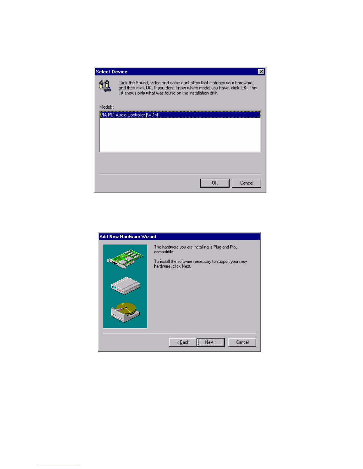
81 Chapter 6
11. In the Select Device window, select "VIA PCI Audio Controller
(WDM)" and click "OK".
12. In the Add New Hardware Wizard window, click "Next".
Page 92
PCM-9373 User’s Manual 82
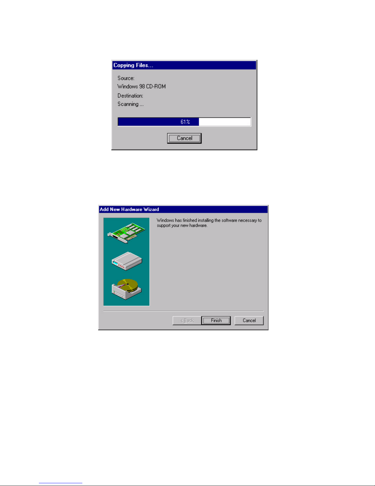
13. The Copying Files... window will appear.
14. In the Add New Hardware Wizard window, click "Finish". Then
reboot the system.
Page 93
83 Chapter 6
6.3.3 Windows NT drivers
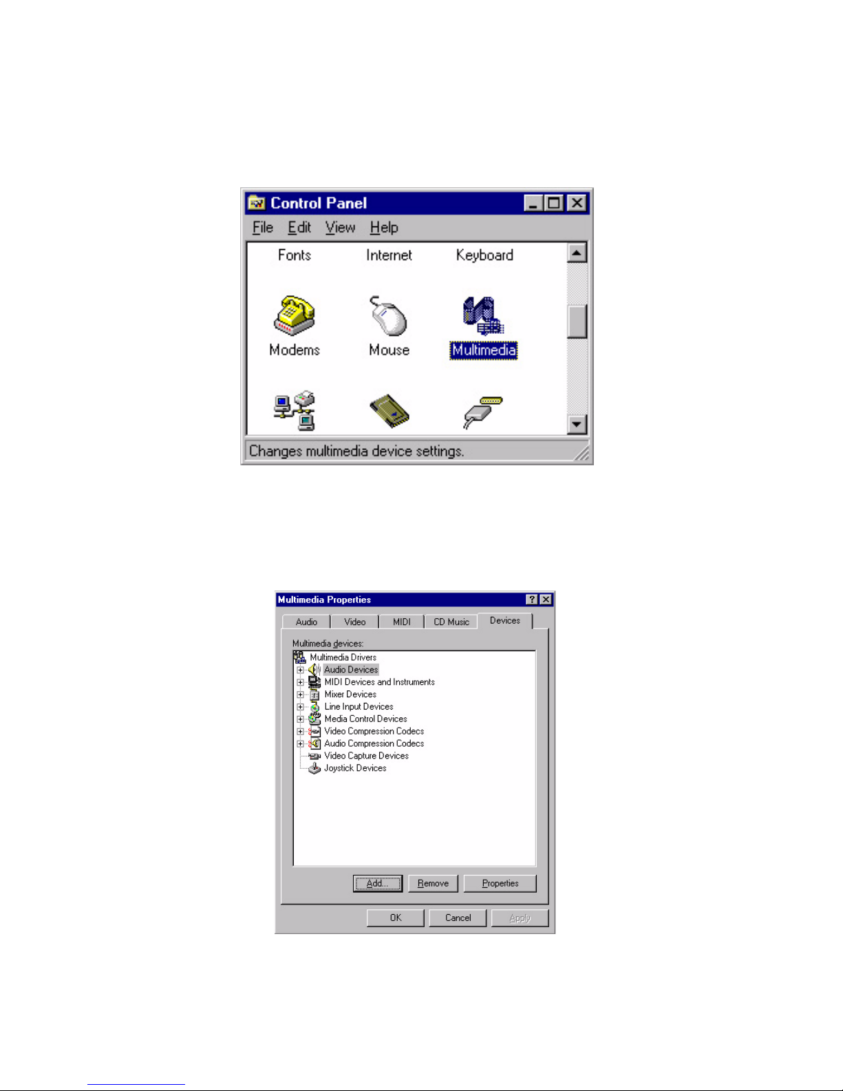
1. Click "Start" and select "Settings". Click "Control Panel" and dou-
ble-click "Multimedia".
2. In the Multimedia Properties window, select the "Devices" tab.
Then select the "Audio Devices" item, and click "Add...".
Page 94
PCM-9373 User’s Manual 84
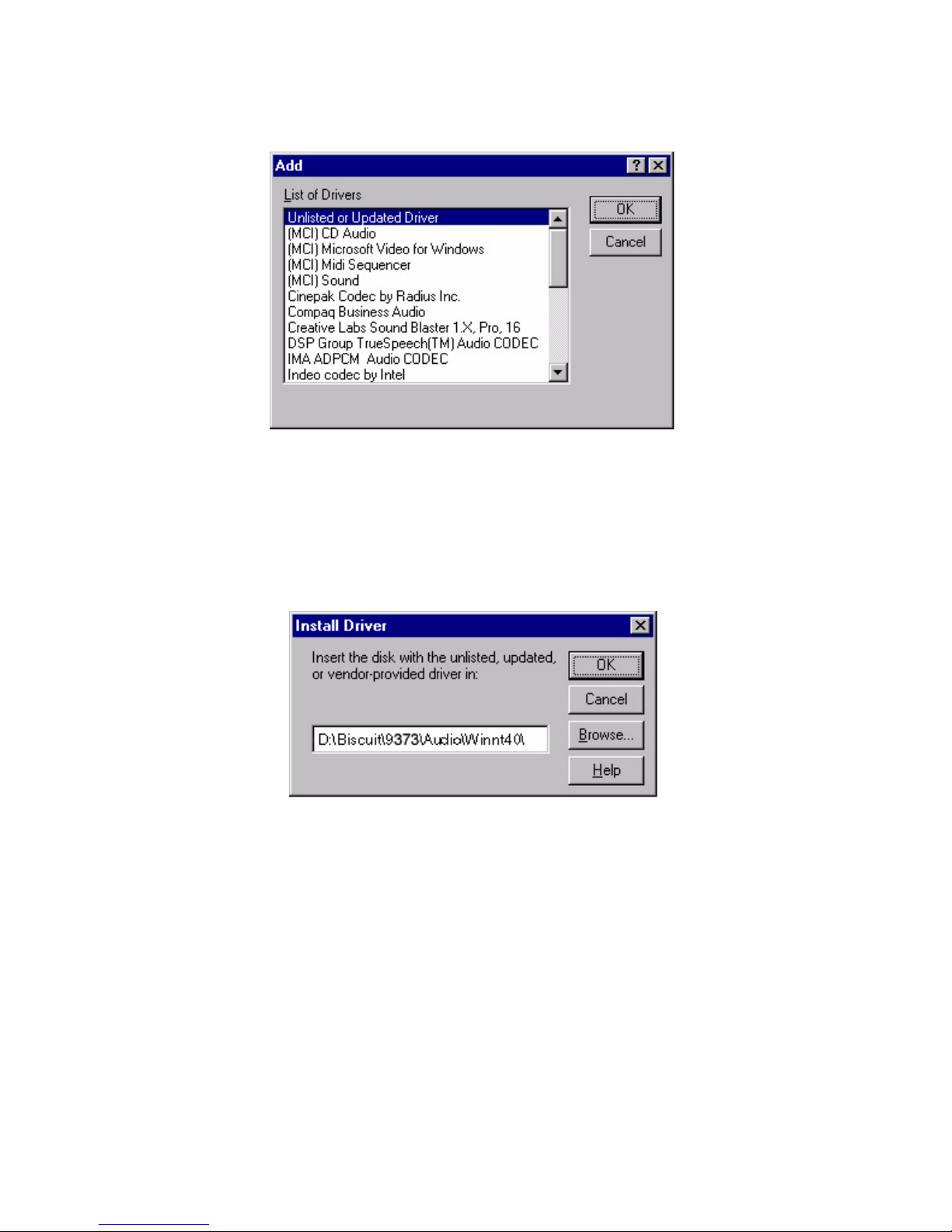
3. In the Add window, select the "Unlisted..." item and click "OK".
4. When the Install Driver window appears, insert the utility disc into
the CD-ROM drive. Type: D:\Biscuit\9373\Audio\WinNT\ Then
click "OK".
Page 95
85 Chapter 6
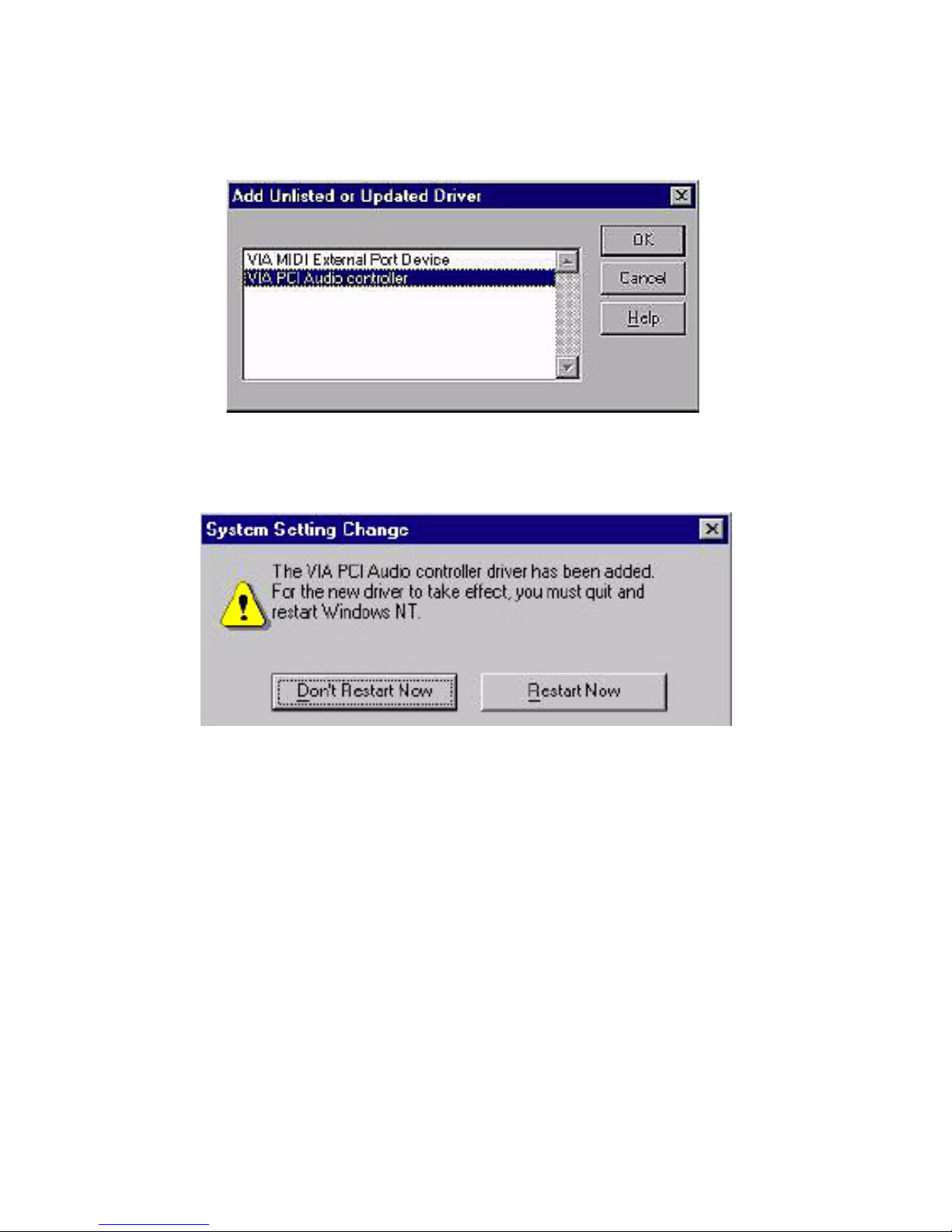
5. In the Add Unlisted or Updated Driver window, select the "VIA
PCI Audio controller" item. Then click "OK".
6. In the System Setting Change window, click "Restart Now".
Page 96
PCM-9373 User’s Manual 86
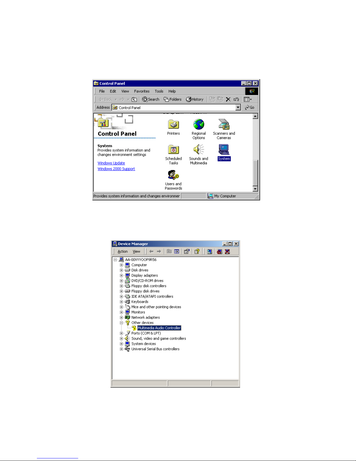
6.3.4 Windows 2000 Drivers
1. Select “System”, “Setting”, “Control Panel” and double click “sys-
tem” icon.
2. Choose “Multimedia Audio Controller” button.
Page 97
87 Chapter 6
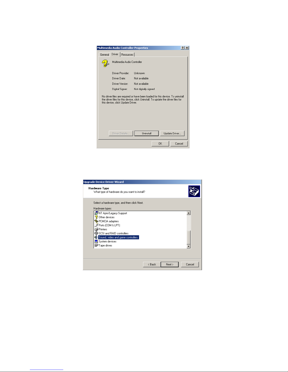
3. Choose “Driver button, press “Update Driver” button.
4. Choose “Sound, video and game controllers”, press “Next”
Page 98
PCM-9373 User’s Manual 88
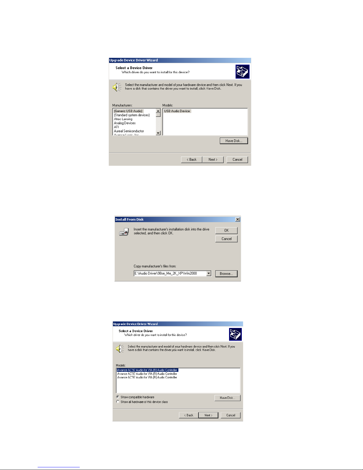
5. Click the “Have Disk...” button
6. Type the path D:\Biscuit\9373\Audio\98se_Me_2k_xp\Win2000
press the “ok” button.
7. Click “Have Disk” button
Page 99
89 Chapter 6
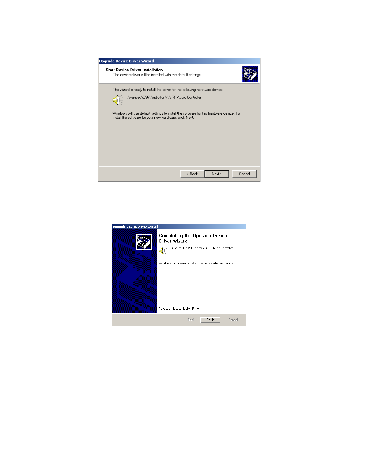
8. Press “Next” button
9. Press “Finish” to reboot
Page 100

PCM-9373 User’s Manual 90
 Loading...